Valve guides JEEP GRAND CHEROKEE 2002 WJ / 2.G Workshop Manual
[x] Cancel search | Manufacturer: JEEP, Model Year: 2002, Model line: GRAND CHEROKEE, Model: JEEP GRAND CHEROKEE 2002 WJ / 2.GPages: 2199, PDF Size: 76.01 MB
Page 1249 of 2199
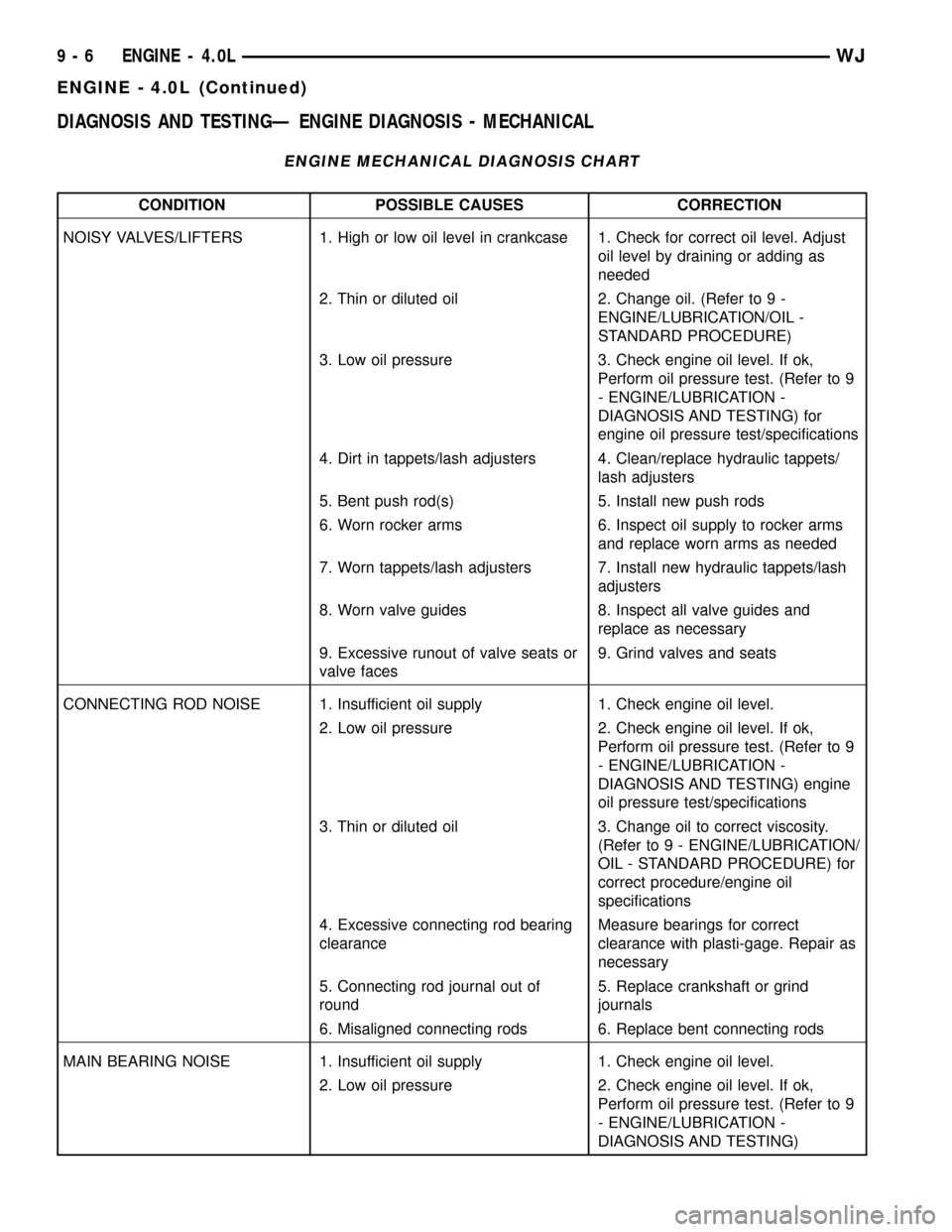
DIAGNOSIS AND TESTINGÐ ENGINE DIAGNOSIS - MECHANICAL
ENGINE MECHANICAL DIAGNOSIS CHART
CONDITION POSSIBLE CAUSES CORRECTION
NOISY VALVES/LIFTERS 1. High or low oil level in crankcase 1. Check for correct oil level. Adjust
oil level by draining or adding as
needed
2. Thin or diluted oil 2. Change oil. (Refer to 9 -
ENGINE/LUBRICATION/OIL -
STANDARD PROCEDURE)
3. Low oil pressure 3. Check engine oil level. If ok,
Perform oil pressure test. (Refer to 9
- ENGINE/LUBRICATION -
DIAGNOSIS AND TESTING) for
engine oil pressure test/specifications
4. Dirt in tappets/lash adjusters 4. Clean/replace hydraulic tappets/
lash adjusters
5. Bent push rod(s) 5. Install new push rods
6. Worn rocker arms 6. Inspect oil supply to rocker arms
and replace worn arms as needed
7. Worn tappets/lash adjusters 7. Install new hydraulic tappets/lash
adjusters
8. Worn valve guides 8. Inspect all valve guides and
replace as necessary
9. Excessive runout of valve seats or
valve faces9. Grind valves and seats
CONNECTING ROD NOISE 1. Insufficient oil supply 1. Check engine oil level.
2. Low oil pressure 2. Check engine oil level. If ok,
Perform oil pressure test. (Refer to 9
- ENGINE/LUBRICATION -
DIAGNOSIS AND TESTING) engine
oil pressure test/specifications
3. Thin or diluted oil 3. Change oil to correct viscosity.
(Refer to 9 - ENGINE/LUBRICATION/
OIL - STANDARD PROCEDURE) for
correct procedure/engine oil
specifications
4. Excessive connecting rod bearing
clearanceMeasure bearings for correct
clearance with plasti-gage. Repair as
necessary
5. Connecting rod journal out of
round5. Replace crankshaft or grind
journals
6. Misaligned connecting rods 6. Replace bent connecting rods
MAIN BEARING NOISE 1. Insufficient oil supply 1. Check engine oil level.
2. Low oil pressure 2. Check engine oil level. If ok,
Perform oil pressure test. (Refer to 9
- ENGINE/LUBRICATION -
DIAGNOSIS AND TESTING)
9 - 6 ENGINE - 4.0LWJ
ENGINE - 4.0L (Continued)
Page 1250 of 2199
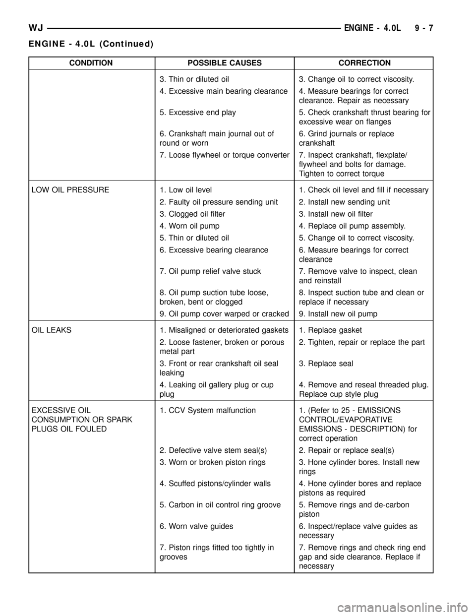
CONDITION POSSIBLE CAUSES CORRECTION
3. Thin or diluted oil 3. Change oil to correct viscosity.
4. Excessive main bearing clearance 4. Measure bearings for correct
clearance. Repair as necessary
5. Excessive end play 5. Check crankshaft thrust bearing for
excessive wear on flanges
6. Crankshaft main journal out of
round or worn6. Grind journals or replace
crankshaft
7. Loose flywheel or torque converter 7. Inspect crankshaft, flexplate/
flywheel and bolts for damage.
Tighten to correct torque
LOW OIL PRESSURE 1. Low oil level 1. Check oil level and fill if necessary
2. Faulty oil pressure sending unit 2. Install new sending unit
3. Clogged oil filter 3. Install new oil filter
4. Worn oil pump 4. Replace oil pump assembly.
5. Thin or diluted oil 5. Change oil to correct viscosity.
6. Excessive bearing clearance 6. Measure bearings for correct
clearance
7. Oil pump relief valve stuck 7. Remove valve to inspect, clean
and reinstall
8. Oil pump suction tube loose,
broken, bent or clogged8. Inspect suction tube and clean or
replace if necessary
9. Oil pump cover warped or cracked 9. Install new oil pump
OIL LEAKS 1. Misaligned or deteriorated gaskets 1. Replace gasket
2. Loose fastener, broken or porous
metal part2. Tighten, repair or replace the part
3. Front or rear crankshaft oil seal
leaking3. Replace seal
4. Leaking oil gallery plug or cup
plug4. Remove and reseal threaded plug.
Replace cup style plug
EXCESSIVE OIL
CONSUMPTION OR SPARK
PLUGS OIL FOULED1. CCV System malfunction 1. (Refer to 25 - EMISSIONS
CONTROL/EVAPORATIVE
EMISSIONS - DESCRIPTION) for
correct operation
2. Defective valve stem seal(s) 2. Repair or replace seal(s)
3. Worn or broken piston rings 3. Hone cylinder bores. Install new
rings
4. Scuffed pistons/cylinder walls 4. Hone cylinder bores and replace
pistons as required
5. Carbon in oil control ring groove 5. Remove rings and de-carbon
piston
6. Worn valve guides 6. Inspect/replace valve guides as
necessary
7. Piston rings fitted too tightly in
grooves7. Remove rings and check ring end
gap and side clearance. Replace if
necessary
WJENGINE - 4.0L 9 - 7
ENGINE - 4.0L (Continued)
Page 1262 of 2199
(2) Lift cover up and position to the side.
(3) Remove air cleaner element.
INSTALLATION - 4.0L
(1) Clean inside of air cleaner housing before
installing new element.
(2) Install air cleaner element into housing.
(3) Latch clips and clamp cover down to secure. Be
sure air cleaner cover is properly seated to air
cleaner housing.
AIR CLEANER HOUSING
REMOVAL - 4.0L
(1) Disconnect air cleaner cover-to-air duct clamp
(Fig. 6).
(2) Disconnect air duct at housing.
(3)Each of the 3 air cleaner housing mount-
ing bolts is attached with 2 nuts (an upper nut
and lower nut). DO NOT REMOVE BOLTS. To
prevent stripping bolts, only remove lower
nuts. The lower housing nuts are located under
left front inner fender (Fig. 6).
(a) To gain access to lower nuts, raise vehicle.
(b) Remove clips retaining rubber inner fender
shield.
(c) Pry back shield enough to gain access to
lower nuts.
(d) Remove 3 nuts.
(e) Remove air cleaner assembly from vehicle.
(4) If resonator is to be removed, disconnect
breather tube at resonator, disconnect air duct clamp
at resonator (Fig. 6)and remove 1 resonator mount-
ing bolt. Remove resonator from throttle body by
loosening clamp (Fig. 7).
INSTALLATION - 4.0L
(1) Position air cleaner assembly to body and
install 3 nuts. Tighten nuts to 10 N´m (93 in. lbs.)
torque.To prevent excessive vibration transmit-
ted through housing, the nuts must be properly
torqued. Do not overtighten nuts.
(2) If resonator was removed: Install resonator and
bolts. Tighten bolts to 4 N´m (35 in. lbs.) torque.
Tighten clamp at throttle body to 4 N´m (35 in. lbs.)
torque.
(3) Position fender liner and install clips.
(4) Connect air duct at housing (Fig. 6).
(5) Tighten air duct clamp.
CYLINDER HEAD
DESCRIPTION
The cylinder head is made of cast iron containing
twelve valves made of chrome plated heat resistant
steel, valve stem seals, springs, retainers and keep-
ers. The cylinder head and valve seats can be resur-
faced for service purposes.
The valve guides are integral to the cylinder head,
They are not replaceable. However, they are service-
able.
The cylinder head uses dual quench-type design
combustion chambers which cause turbulence in the
cylinders allowing faster burning of the air/fuel mix-
ture, resulting in better fuel economy (Fig. 8).
REMOVAL
NOTE: This procedure can be done with the engine
in or out of the vehicle.
(1) Disconnect the battery negative cable.
WARNING: DO NOT REMOVE THE CYLINDER
BLOCK DRAIN PLUGS OR LOOSEN THE RADIATOR
DRAIN COCK WITH THE SYSTEM HOT AND PRES-
SURIZED BECAUSE SERIOUS BURNS FROM THE
COOLANT CAN OCCUR.
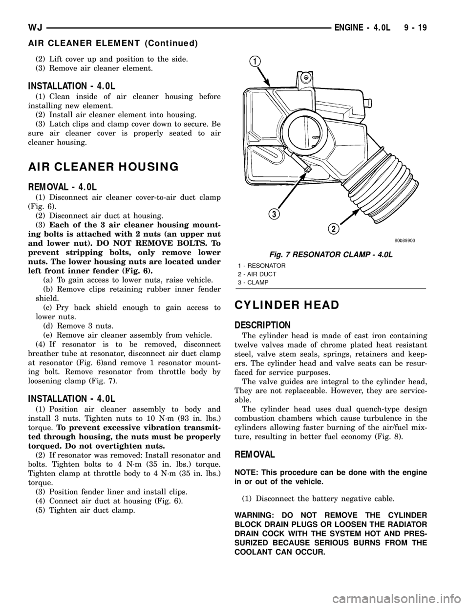
Fig. 7 RESONATOR CLAMP - 4.0L
1 - RESONATOR
2 - AIR DUCT
3 - CLAMP
WJENGINE - 4.0L 9 - 19
AIR CLEANER ELEMENT (Continued)
Page 1266 of 2199
CLEANING
Remove any original sealer from the cover sealing
surface of the engine cylinder head and clean the
surface using a fabric cleaner.
Remove all residue from the sealing surface using
a clean, dry cloth.
INSPECTION
Inspect the engine cylinder head cover for cracks.
Replace the cover, if cracked.
The original dark grey gasket material should
NOT be removed. If sections of the gasket material
are missing or are compressed, replace the engine
cylinder head cover. However, sections with minor
damage such as small cracks, cuts or chips may be
repaired with a hand held applicator. The new mate-
rial must be smoothed over to maintain gasket
height. Allow the gasket material to cure prior to
engine cylinder head cover installation.
INSTALLATION
The cylinder head cover is isolated from the cylin-
der head via grommets and a reusable molded rubber
gasket. The grommet and limiter are retained in the
cylinder head cover.
(1) If a replacement cover is installed, transfer the
CCV valve grommet and oil filler cap from the origi-
nal cover to the replacement cover.
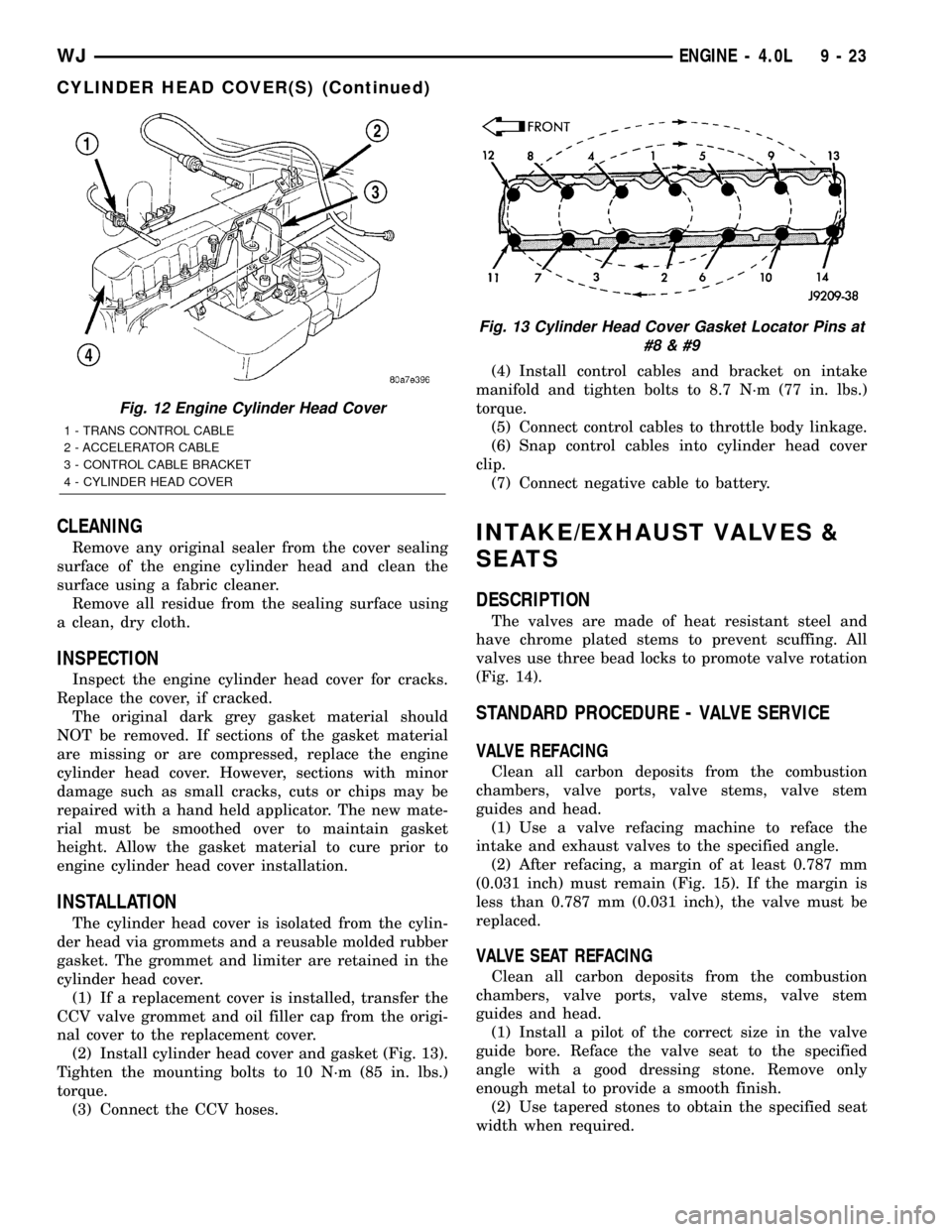
(2) Install cylinder head cover and gasket (Fig. 13).
Tighten the mounting bolts to 10 N´m (85 in. lbs.)
torque.
(3) Connect the CCV hoses.(4) Install control cables and bracket on intake
manifold and tighten bolts to 8.7 N´m (77 in. lbs.)
torque.
(5) Connect control cables to throttle body linkage.
(6) Snap control cables into cylinder head cover
clip.
(7) Connect negative cable to battery.
INTAKE/EXHAUST VALVES &
SEATS
DESCRIPTION
The valves are made of heat resistant steel and
have chrome plated stems to prevent scuffing. All
valves use three bead locks to promote valve rotation
(Fig. 14).
STANDARD PROCEDURE - VALVE SERVICE
VALVE REFACING
Clean all carbon deposits from the combustion
chambers, valve ports, valve stems, valve stem
guides and head.
(1) Use a valve refacing machine to reface the
intake and exhaust valves to the specified angle.
(2) After refacing, a margin of at least 0.787 mm
(0.031 inch) must remain (Fig. 15). If the margin is
less than 0.787 mm (0.031 inch), the valve must be
replaced.
VALVE SEAT REFACING
Clean all carbon deposits from the combustion
chambers, valve ports, valve stems, valve stem
guides and head.
(1) Install a pilot of the correct size in the valve
guide bore. Reface the valve seat to the specified
angle with a good dressing stone. Remove only
enough metal to provide a smooth finish.
(2) Use tapered stones to obtain the specified seat
width when required.
Fig. 12 Engine Cylinder Head Cover
1 - TRANS CONTROL CABLE
2 - ACCELERATOR CABLE
3 - CONTROL CABLE BRACKET
4 - CYLINDER HEAD COVER
Fig. 13 Cylinder Head Cover Gasket Locator Pins at
#8
WJENGINE - 4.0L 9 - 23
CYLINDER HEAD COVER(S) (Continued)
Page 1268 of 2199
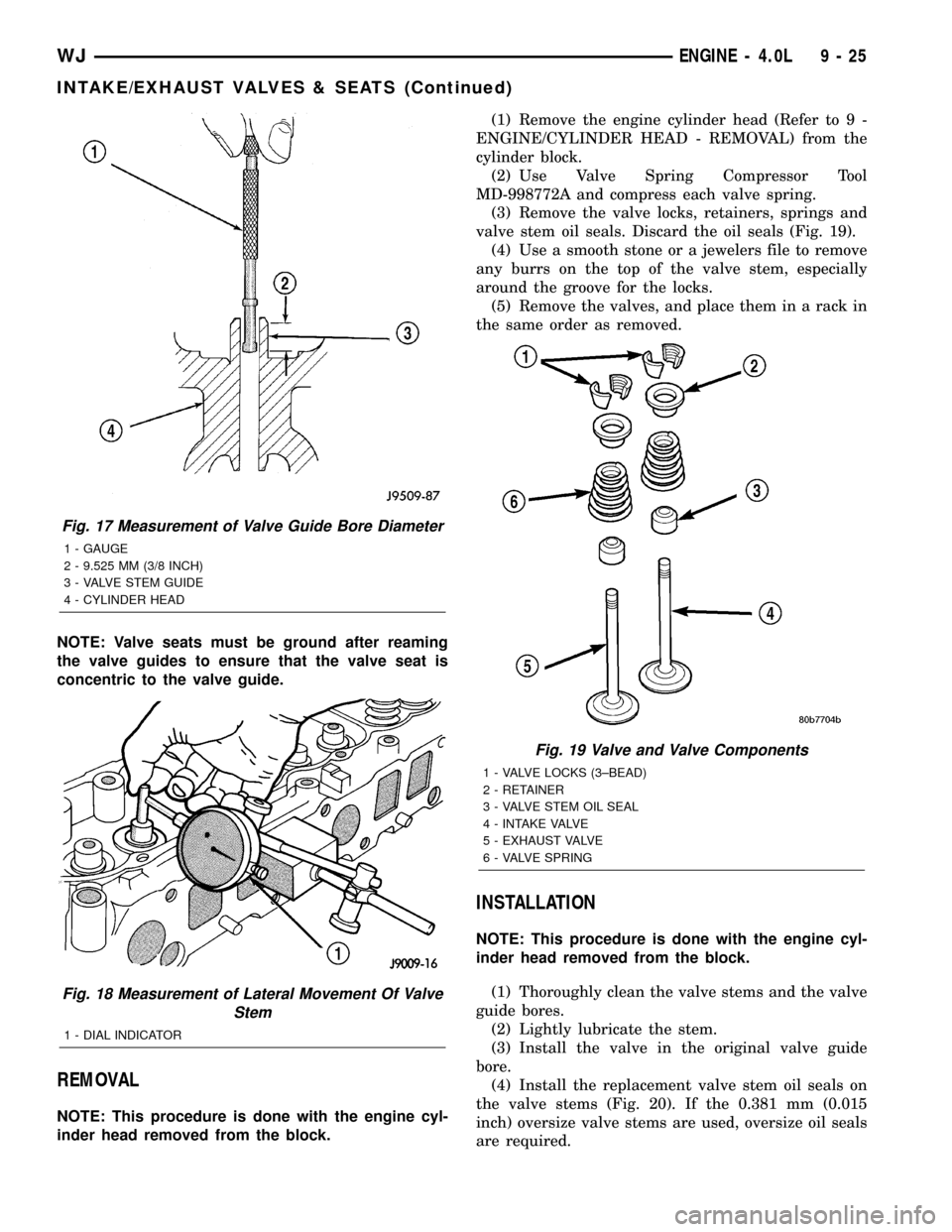
NOTE: Valve seats must be ground after reaming
the valve guides to ensure that the valve seat is
concentric to the valve guide.
REMOVAL
NOTE: This procedure is done with the engine cyl-
inder head removed from the block.(1) Remove the engine cylinder head (Refer to 9 -
ENGINE/CYLINDER HEAD - REMOVAL) from the
cylinder block.
(2) Use Valve Spring Compressor Tool
MD-998772A and compress each valve spring.
(3) Remove the valve locks, retainers, springs and
valve stem oil seals. Discard the oil seals (Fig. 19).
(4) Use a smooth stone or a jewelers file to remove
any burrs on the top of the valve stem, especially
around the groove for the locks.
(5) Remove the valves, and place them in a rack in
the same order as removed.
INSTALLATION
NOTE: This procedure is done with the engine cyl-
inder head removed from the block.
(1) Thoroughly clean the valve stems and the valve
guide bores.
(2) Lightly lubricate the stem.
(3) Install the valve in the original valve guide
bore.
(4) Install the replacement valve stem oil seals on
the valve stems (Fig. 20). If the 0.381 mm (0.015
inch) oversize valve stems are used, oversize oil seals
are required.
Fig. 17 Measurement of Valve Guide Bore Diameter
1 - GAUGE
2 - 9.525 MM (3/8 INCH)
3 - VALVE STEM GUIDE
4 - CYLINDER HEAD
Fig. 18 Measurement of Lateral Movement Of Valve
Stem
1 - DIAL INDICATOR
Fig. 19 Valve and Valve Components
1 - VALVE LOCKS (3±BEAD)
2 - RETAINER
3 - VALVE STEM OIL SEAL
4 - INTAKE VALVE
5 - EXHAUST VALVE
6 - VALVE SPRING
WJENGINE - 4.0L 9 - 25
INTAKE/EXHAUST VALVES & SEATS (Continued)
Page 1271 of 2199
VALVE SPRINGS
DESCRIPTION
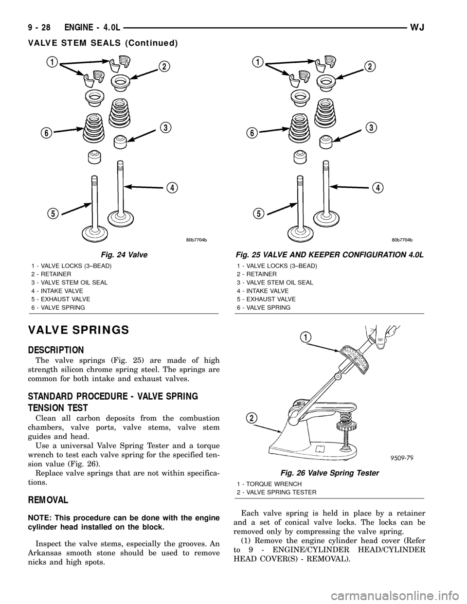
The valve springs (Fig. 25) are made of high
strength silicon chrome spring steel. The springs are
common for both intake and exhaust valves.
STANDARD PROCEDURE - VALVE SPRING
TENSION TEST
Clean all carbon deposits from the combustion
chambers, valve ports, valve stems, valve stem
guides and head.
Use a universal Valve Spring Tester and a torque
wrench to test each valve spring for the specified ten-
sion value (Fig. 26).
Replace valve springs that are not within specifica-
tions.
REMOVAL
NOTE: This procedure can be done with the engine
cylinder head installed on the block.
Inspect the valve stems, especially the grooves. An
Arkansas smooth stone should be used to remove
nicks and high spots.Each valve spring is held in place by a retainer
and a set of conical valve locks. The locks can be
removed only by compressing the valve spring.
(1) Remove the engine cylinder head cover (Refer
to 9 - ENGINE/CYLINDER HEAD/CYLINDER
HEAD COVER(S) - REMOVAL).
Fig. 24 Valve
1 - VALVE LOCKS (3±BEAD)
2 - RETAINER
3 - VALVE STEM OIL SEAL
4 - INTAKE VALVE
5 - EXHAUST VALVE
6 - VALVE SPRING
Fig. 25 VALVE AND KEEPER CONFIGURATION 4.0L
1 - VALVE LOCKS (3±BEAD)
2 - RETAINER
3 - VALVE STEM OIL SEAL
4 - INTAKE VALVE
5 - EXHAUST VALVE
6 - VALVE SPRING
Fig. 26 Valve Spring Tester
1 - TORQUE WRENCH
2 - VALVE SPRING TESTER
9 - 28 ENGINE - 4.0LWJ
VALVE STEM SEALS (Continued)
Page 1304 of 2199
ENGINE - 4.7L
TABLE OF CONTENTS
page page
ENGINE - 4.7L
DESCRIPTIONÐ4.7L ENGINE.............63
DIAGNOSIS AND TESTING
DIAGNOSIS AND TESTING - ENGINE
DIAGNOSIS - INTRODUCTION...........64
DIAGNOSIS AND TESTING - ENGINE
DIAGNOSIS - PERFORMANCE...........65
DIAGNOSIS AND TESTING - ENGINE
DIAGNOSIS - MECHANICAL.............66
DIAGNOSIS AND TESTING - ENGINE
DIAGNOSIS - LUBRICATION.............67
DIAGNOSIS AND TESTING - CYLINDER
COMPRESSION PRESSURE.............68
DIAGNOSIS AND TESTING - CYLINDER
COMBUSTION PRESSURE LEAKAGE......69
STANDARD PROCEDURE
STANDARD PROCEDURE - REPAIR
DAMAGED OR WORN THREADS.........70
STANDARD PROCEDURE - FORM-IN-
PLACE GASKETS AND SEALERS.........70
STANDARD PROCEDURE - ENGINE
GASKET SURFACE PREPARATION........70
STANDARD PROCEDURE - ENGINE CORE
AND OIL GALLERY PLUGS..............71
REMOVAL.............................71
INSTALLATION.........................73
SPECIFICATIONS
4.7L ENGINE.........................74
SPECIFICATIONS - 4.7L H.O. ENGINE.....77
TORQUE............................79
SPECIAL TOOLS
4.7L ENGINE.........................80
AIR CLEANER ELEMENT
REMOVAL - 4.7L........................83
INSTALLATION - 4.7L....................83
AIR CLEANER HOUSING
REMOVAL - 4.7L........................84
INSTALLATION - 4.7L....................84
CYLINDER HEAD - LEFT
DESCRIPTION
DESCRIPTION - CYLINDER HEAD........84
DESCRIPTION - VALVE GUIDES..........84
DIAGNOSIS AND TESTING
DIAGNOSIS AND TESTING - HYDRAULIC
LASH ADJUSTER.....................84
DIAGNOSIS AND TESTINGÐCYLINDER
HEAD GASKET.......................85
REMOVAL.............................85
CLEANING............................86
INSPECTION..........................87INSTALLATION.........................87
CAMSHAFT(S) - LEFT
DESCRIPTION.........................88
REMOVAL.............................89
INSTALLATION.........................90
CYLINDER HEAD COVER(S) - LEFT
DESCRIPTION.........................93
REMOVAL - LEFT SIDE..................93
CLEANING............................93
INSTALLATIONÐLEFT SIDE...............93
INTAKE/EXHAUST VALVES & SEATS
DESCRIPTION.........................94
STANDARD PROCEDUREÐREFACING......94
REMOVAL.............................94
INSTALLATION.........................95
ROCKER ARM / ADJUSTER ASSEMBLY
DESCRIPTION.........................96
REMOVAL.............................96
INSTALLATION.........................96
VALVE SPRINGS
DESCRIPTION.........................97
VALVE STEM SEALS
DESCRIPTION.........................97
CYLINDER HEAD - RIGHT
DESCRIPTION
DESCRIPTION - CYLINDER HEAD........97
DESCRIPTION - VALVE GUIDES..........97
DIAGNOSIS AND TESTING
DIAGNOSIS AND TESTINGÐCYLINDER
HEAD GASKET.......................97
DIAGNOSIS AND TESTING - HYDRAULIC
LASH ADJUSTER.....................98
REMOVAL.............................98
CLEANING............................99
INSPECTION..........................99
INSTALLATION.........................99
CAMSHAFT(S) - RIGHT
DESCRIPTION........................100
REMOVAL............................100
INSTALLATION........................102
CYLINDER HEAD COVER(S) - RIGHT
DESCRIPTION........................104
REMOVAL - RIGHT SIDE................104
CLEANING...........................104
INSTALLATION - RIGHT SIDE.............104
INTAKE/EXHAUST VALVES & SEATS
DESCRIPTION........................104
STANDARD PROCEDUREÐREFACING.....105
REMOVAL............................105
INSTALLATION........................106
WJENGINE - 4.7L 9 - 61
Page 1309 of 2199
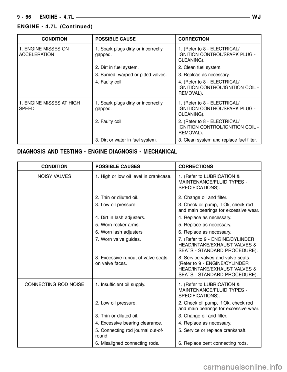
CONDITION POSSIBLE CAUSE CORRECTION
1. ENGINE MISSES ON
ACCELERATION1. Spark plugs dirty or incorrectly
gapped.1. (Refer to 8 - ELECTRICAL/
IGNITION CONTROL/SPARK PLUG -
CLEANING).
2. Dirt in fuel system. 2. Clean fuel system.
3. Burned, warped or pitted valves. 3. Replcae as necessary.
4. Faulty coil. 4. (Refer to 8 - ELECTRICAL/
IGNITION CONTROL/IGNITION COIL -
REMOVAL).
1. ENGINE MISSES AT HIGH
SPEED1. Spark plugs dirty or incorrectly
gapped.1. (Refer to 8 - ELECTRICAL/
IGNITION CONTROL/SPARK PLUG -
CLEANING).
2. Faulty coil. 2. (Refer to 8 - ELECTRICAL/
IGNITION CONTROL/IGNITION COIL -
REMOVAL).
3. Dirt or water in fuel system. 3. Clean system and replace fuel filter.
DIAGNOSIS AND TESTING - ENGINE DIAGNOSIS - MECHANICAL
CONDITION POSSIBLE CAUSES CORRECTIONS
NOISY VALVES 1. High or low oil level in crankcase. 1. (Refer to LUBRICATION &
MAINTENANCE/FLUID TYPES -
SPECIFICATIONS).
2. Thin or diluted oil. 2. Change oil and filter.
3. Low oil pressure. 3. Check oil pump, if Ok, check rod
and main bearings for excessive wear.
4. Dirt in lash adjusters. 4. Replace as necessary.
5. Worn rocker arms. 5. Replace as necessary.
6. Worn lash adjusters 6. Replace as necessary.
7. Worn valve guides. 7. (Refer to 9 - ENGINE/CYLINDER
HEAD/INTAKE/EXHAUST VALVES &
SEATS - STANDARD PROCEDURE).
8. Excessive runout of valve seats
on valve faces.8. Service valves and valve seats.
(Refer to 9 - ENGINE/CYLINDER
HEAD/INTAKE/EXHAUST VALVES &
SEATS - STANDARD PROCEDURE).
CONNECTING ROD NOISE 1. Insufficient oil supply. 1. (Refer to LUBRICATION &
MAINTENANCE/FLUID TYPES -
SPECIFICATIONS).
2. Low oil pressure. 2. Check oil pump, if Ok, check rod
and main bearings for excessive wear.
3. Thin or diluted oil. 3. Change oil and filter.
4. Excessive bearing clearance. 4. Replace as necessary.
5. Connecting rod journal out-of-
round.5. Service or replace crankshaft.
6. Misaligned connecting rods. 6. Replace bent connecting rods.
9 - 66 ENGINE - 4.7LWJ
ENGINE - 4.7L (Continued)
Page 1311 of 2199
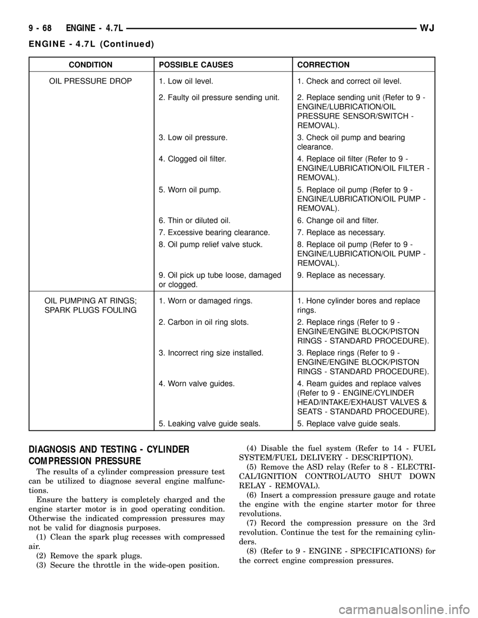
CONDITION POSSIBLE CAUSES CORRECTION
OIL PRESSURE DROP 1. Low oil level. 1. Check and correct oil level.
2. Faulty oil pressure sending unit. 2. Replace sending unit (Refer to 9 -
ENGINE/LUBRICATION/OIL
PRESSURE SENSOR/SWITCH -
REMOVAL).
3. Low oil pressure. 3. Check oil pump and bearing
clearance.
4. Clogged oil filter. 4. Replace oil filter (Refer to 9 -
ENGINE/LUBRICATION/OIL FILTER -
REMOVAL).
5. Worn oil pump. 5. Replace oil pump (Refer to 9 -
ENGINE/LUBRICATION/OIL PUMP -
REMOVAL).
6. Thin or diluted oil. 6. Change oil and filter.
7. Excessive bearing clearance. 7. Replace as necessary.
8. Oil pump relief valve stuck. 8. Replace oil pump (Refer to 9 -
ENGINE/LUBRICATION/OIL PUMP -
REMOVAL).
9. Oil pick up tube loose, damaged
or clogged.9. Replace as necessary.
OIL PUMPING AT RINGS;
SPARK PLUGS FOULING1. Worn or damaged rings. 1. Hone cylinder bores and replace
rings.
2. Carbon in oil ring slots. 2. Replace rings (Refer to 9 -
ENGINE/ENGINE BLOCK/PISTON
RINGS - STANDARD PROCEDURE).
3. Incorrect ring size installed. 3. Replace rings (Refer to 9 -
ENGINE/ENGINE BLOCK/PISTON
RINGS - STANDARD PROCEDURE).
4. Worn valve guides. 4. Ream guides and replace valves
(Refer to 9 - ENGINE/CYLINDER
HEAD/INTAKE/EXHAUST VALVES &
SEATS - STANDARD PROCEDURE).
5. Leaking valve guide seals. 5. Replace valve guide seals.
DIAGNOSIS AND TESTING - CYLINDER
COMPRESSION PRESSURE
The results of a cylinder compression pressure test
can be utilized to diagnose several engine malfunc-
tions.
Ensure the battery is completely charged and the
engine starter motor is in good operating condition.
Otherwise the indicated compression pressures may
not be valid for diagnosis purposes.
(1) Clean the spark plug recesses with compressed
air.
(2) Remove the spark plugs.
(3) Secure the throttle in the wide-open position.(4) Disable the fuel system (Refer to 14 - FUEL
SYSTEM/FUEL DELIVERY - DESCRIPTION).
(5) Remove the ASD relay (Refer to 8 - ELECTRI-
CAL/IGNITION CONTROL/AUTO SHUT DOWN
RELAY - REMOVAL).
(6) Insert a compression pressure gauge and rotate
the engine with the engine starter motor for three
revolutions.
(7) Record the compression pressure on the 3rd
revolution. Continue the test for the remaining cylin-
ders.
(8) (Refer to 9 - ENGINE - SPECIFICATIONS) for
the correct engine compression pressures.
9 - 68 ENGINE - 4.7LWJ
ENGINE - 4.7L (Continued)
Page 1327 of 2199
AIR CLEANER HOUSING
REMOVAL - 4.7L
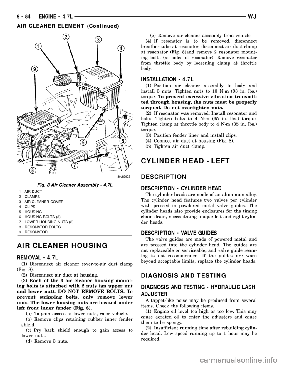
(1) Disconnect air cleaner cover-to-air duct clamp
(Fig. 8).
(2) Disconnect air duct at housing.
(3)Each of the 3 air cleaner housing mount-
ing bolts is attached with 2 nuts (an upper nut
and lower nut). DO NOT REMOVE BOLTS. To
prevent stripping bolts, only remove lower
nuts. The lower housing nuts are located under
left front inner fender (Fig. 8).
(a) To gain access to lower nuts, raise vehicle.
(b) Remove clips retaining rubber inner fender
shield.
(c) Pry back shield enough to gain access to
lower nuts.
(d) Remove 3 nuts.(e) Remove air cleaner assembly from vehicle.
(4) If resonator is to be removed, disconnect
breather tube at resonator, disconnect air duct clamp
at resonator (Fig. 8)and remove 2 resonator mount-
ing bolts (at sides of resonator). Remove resonator
from throttle body by loosening clamp at throttle
body.
INSTALLATION - 4.7L
(1) Position air cleaner assembly to body and
install 3 nuts. Tighten nuts to 10 N´m (93 in. lbs.)
torque.To prevent excessive vibration transmit-
ted through housing, the nuts must be properly
torqued. Do not overtighten nuts.
(2) If resonator was removed: Install resonator and
bolts. Tighten bolts to 4 N´m (35 in. lbs.) torque.
Tighten clamp at throttle body to 4 N´m (35 in. lbs.)
torque.
(3) Position fender liner and install clips.
(4) Connect air duct at housing (Fig. 8).
(5) Tighten air duct clamp.
CYLINDER HEAD - LEFT
DESCRIPTION
DESCRIPTION - CYLINDER HEAD
The cylinder heads are made of an aluminum alloy.
The cylinder head features two valves per cylinder
with pressed in powdered metal valve guides. The
cylinder heads also provide enclosures for the timing
chain drain, necessitating unique left and right cylin-
der heads.
DESCRIPTION - VALVE GUIDES
The valve guides are made of powered metal and
are pressed into the cylinder head. The guides are
not replaceable or serviceable, and valve guide ream-
ing is not recommended. If the guides are worn
beyond acceptable limits, replace the cylinder heads.
DIAGNOSIS AND TESTING
DIAGNOSIS AND TESTING - HYDRAULIC LASH
ADJUSTER
A tappet-like noise may be produced from several
items. Check the following items.
(1) Engine oil level too high or too low. This may
cause aerated oil to enter the adjusters and cause
them to be spongy.
(2) Insufficient running time after rebuilding cylin-
der head. Low speed running up to 1 hour may be
required.
Fig. 8 Air Cleaner Assembly - 4.7L
1 - AIR DUCT
2 - CLAMPS
3 - AIR CLEANER COVER
4 - CLIPS
5 - HOUSING
6 - HOUSING BOLTS (3)
7 - LOWER HOUSING NUTS (3)
8 - RESONATOR BOLTS
9 - RESONATOR
9 - 84 ENGINE - 4.7LWJ
AIR CLEANER ELEMENT (Continued)