front axle control arm bush JEEP GRAND CHEROKEE 2002 WJ / 2.G Workshop Manual
[x] Cancel search | Manufacturer: JEEP, Model Year: 2002, Model line: GRAND CHEROKEE, Model: JEEP GRAND CHEROKEE 2002 WJ / 2.GPages: 2199, PDF Size: 76.01 MB
Page 27 of 2199

FRONT
TABLE OF CONTENTS
page page
FRONT
DESCRIPTION..........................6
STANDARD PROCEDURE - SERVICE
WARNINGS AND CAUTIONS..............6
SPECIFICATIONS
TORQUE CHART......................7
SPECIAL TOOLS
FRONT SUSPENSION...................8
BUSHINGS
REMOVAL.............................9
INSTALLATION..........................9
HUB / BEARING
DESCRIPTION..........................9
OPERATION............................9
REMOVAL.............................9
INSTALLATION.........................10
KNUCKLE
DESCRIPTION.........................10
OPERATION...........................10
REMOVAL - STEERING KNUCKLE..........10
INSTALLATION.........................10
LOWER BALL JOINT
REMOVAL.............................11
LOWER CONTROL ARM
DESCRIPTION.........................11
OPERATION...........................11
REMOVAL.............................11
INSTALLATION.........................11SHOCK
DESCRIPTION.........................12
OPERATION...........................12
REMOVAL.............................12
INSTALLATION.........................12
SPRING
DESCRIPTION.........................12
OPERATION...........................13
REMOVAL.............................13
INSTALLATION.........................13
STABILIZER BAR
DESCRIPTION.........................14
OPERATION...........................14
REMOVAL.............................14
INSTALLATION.........................14
TRACK BAR
DESCRIPTION.........................14
OPERATION...........................14
REMOVAL.............................14
INSTALLATION.........................14
UPPER BALL JOINT
REMOVAL.............................15
UPPER CONTROL ARM
DESCRIPTION.........................16
OPERATION...........................16
REMOVAL.............................16
INSTALLATION.........................16
FRONT
DESCRIPTION
The front suspension (Fig. 1) is a link/coil design
comprised of :
²Drive axle
²Shock absorbers
²Coil springs
²Upper and lower suspension arms
²Stabilizer bar
²Track bar
²Jounce bumpers
CAUTION: Components attached with a nut and cot-
ter pin must be torqued to specification. Then if the
slot in the nut does not line up with the cotter pin
hole, tighten nut until it is aligned. Never loosen the
nut to align the cotter pin hole.CAUTION: Suspension components with rubber
bushings must be tightened with the vehicle at nor-
mal ride height. It is important to have the springs
supporting the weight of the vehicle when the fas-
teners are torqued. If springs are not at their normal
ride position, vehicle ride comfort will be affected
and cause premature bushing wear.
STANDARD PROCEDURE - SERVICE
WARNINGS AND CAUTIONS
CAUTION: Suspension components with rubber
bushings must be tightened with the vehicle at nor-
mal ride height. It is important to have the springs
supporting the weight of the vehicle when the fas-
teners are torqued. If springs are not at their normal
ride position, vehicle ride comfort will be affected
and cause premature bushing wear.
2 - 6 FRONTWJ
Page 32 of 2199

LOWER BALL JOINT
REMOVAL
Ball stud service procedures below require removal
of the hub bearing and axle shaft. Removal and
installation of upper and lower ball studs require the
use of Tool Kit 6289.
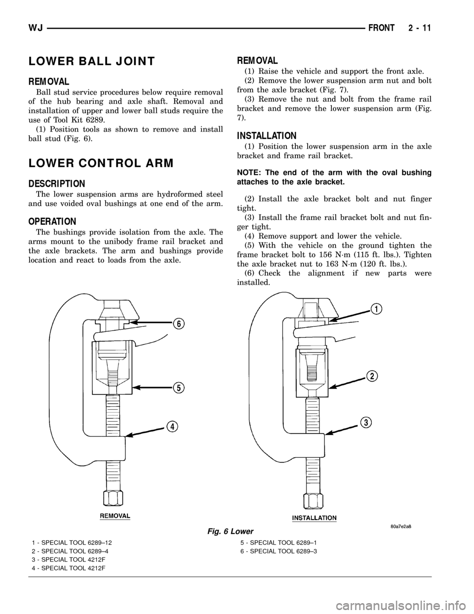
(1) Position tools as shown to remove and install
ball stud (Fig. 6).
LOWER CONTROL ARM
DESCRIPTION
The lower suspension arms are hydroformed steel
and use voided oval bushings at one end of the arm.
OPERATION
The bushings provide isolation from the axle. The
arms mount to the unibody frame rail bracket and
the axle brackets. The arm and bushings provide
location and react to loads from the axle.
REMOVAL
(1) Raise the vehicle and support the front axle.
(2) Remove the lower suspension arm nut and bolt
from the axle bracket (Fig. 7).
(3) Remove the nut and bolt from the frame rail
bracket and remove the lower suspension arm (Fig.
7).
INSTALLATION
(1) Position the lower suspension arm in the axle
bracket and frame rail bracket.
NOTE: The end of the arm with the oval bushing
attaches to the axle bracket.
(2) Install the axle bracket bolt and nut finger
tight.
(3) Install the frame rail bracket bolt and nut fin-
ger tight.
(4) Remove support and lower the vehicle.
(5) With the vehicle on the ground tighten the
frame bracket bolt to 156 N´m (115 ft. lbs.). Tighten
the axle bracket nut to 163 N´m (120 ft. lbs.).
(6) Check the alignment if new parts were
installed.
Fig. 6 Lower
1 - SPECIAL TOOL 6289±12
2 - SPECIAL TOOL 6289±4
3 - SPECIAL TOOL 4212F
4 - SPECIAL TOOL 4212F5 - SPECIAL TOOL 6289±1
6 - SPECIAL TOOL 6289±3
WJFRONT 2 - 11
Page 37 of 2199

UPPER CONTROL ARM
DESCRIPTION
The upper suspension arms are hydroformed steel
and use rubber bushings at each end of the arm.
OPERATION
The arms mount to the unibody frame rail bracket
and the axle brackets. The arm and bushings provide
location and react to loads from the axle. The bush-
ings provide isolation from the axle.
REMOVAL
(1) Raise vehicle and support the axle.
(2) Remove the upper suspension arm mounting
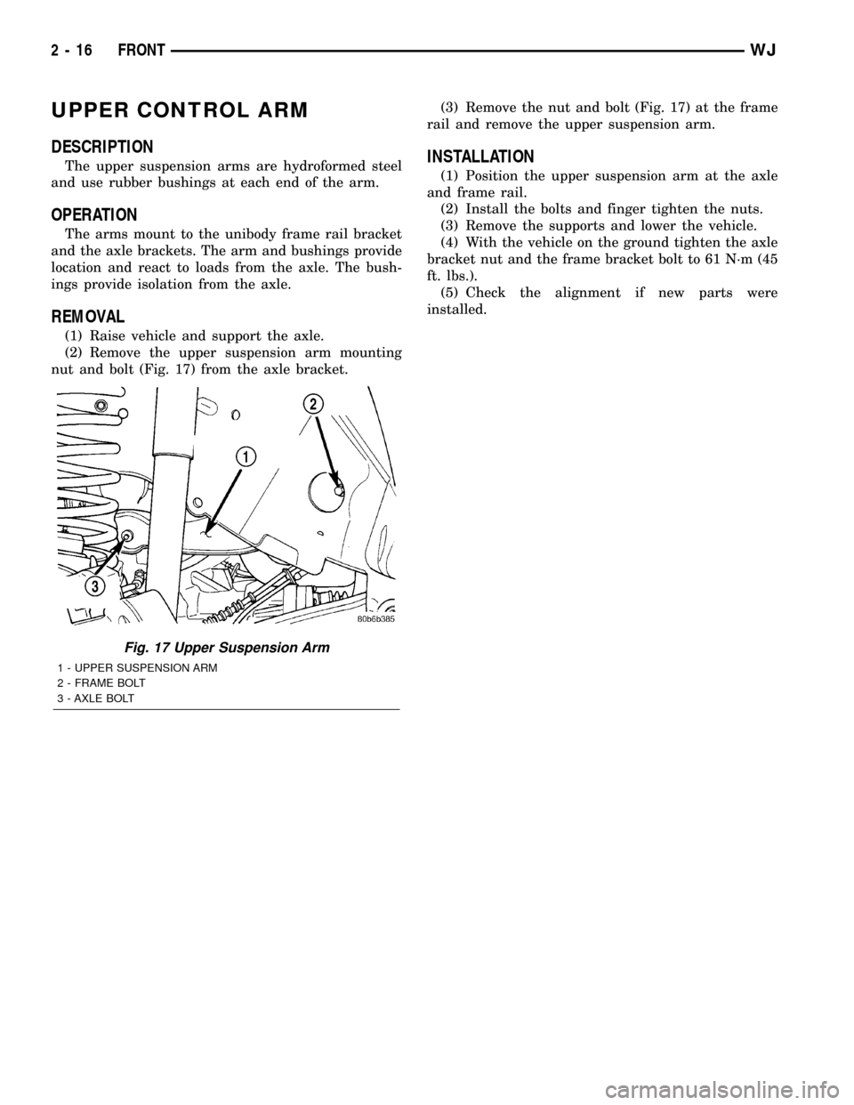
nut and bolt (Fig. 17) from the axle bracket.(3) Remove the nut and bolt (Fig. 17) at the frame
rail and remove the upper suspension arm.
INSTALLATION
(1) Position the upper suspension arm at the axle
and frame rail.
(2) Install the bolts and finger tighten the nuts.
(3) Remove the supports and lower the vehicle.
(4) With the vehicle on the ground tighten the axle
bracket nut and the frame bracket bolt to 61 N´m (45
ft. lbs.).
(5) Check the alignment if new parts were
installed.
Fig. 17 Upper Suspension Arm
1 - UPPER SUSPENSION ARM
2 - FRAME BOLT
3 - AXLE BOLT
2 - 16 FRONTWJ