ground JEEP GRAND CHEROKEE 2002 WJ / 2.G Workshop Manual
[x] Cancel search | Manufacturer: JEEP, Model Year: 2002, Model line: GRAND CHEROKEE, Model: JEEP GRAND CHEROKEE 2002 WJ / 2.GPages: 2199, PDF Size: 76.01 MB
Page 18 of 2199

JUMP STARTING
STANDARD PROCEDURE - JUMP STARTING
WARNING: REVIEW ALL SAFETY PRECAUTIONS
AND WARNINGS IN GROUP 8A, BATTERY/START-
ING/CHARGING SYSTEMS DIAGNOSTICS. DO NOT
JUMP START A FROZEN BATTERY, PERSONAL
INJURY CAN RESULT. DO NOT JUMP START WHEN
MAINTENANCE FREE BATTERY INDICATOR DOT IS
YELLOW OR BRIGHT COLOR. DO NOT JUMP
START A VEHICLE WHEN THE BATTERY FLUID IS
BELOW THE TOP OF LEAD PLATES. DO NOT
ALLOW JUMPER CABLE CLAMPS TO TOUCH
EACH OTHER WHEN CONNECTED TO A BOOSTER
SOURCE. DO NOT USE OPEN FLAME NEAR BAT-
TERY. REMOVE METALLIC JEWELRY WORN ON
HANDS OR WRISTS TO AVOID INJURY BY ACCI-
DENTAL ARCING OF BATTERY CURRENT. WHEN
USING A HIGH OUTPUT BOOSTING DEVICE, DO
NOT ALLOW BATTERY VOLTAGE TO EXCEED 16
VOLTS. REFER TO INSTRUCTIONS PROVIDED
WITH DEVICE BEING USED.
CAUTION: When using another vehicle as a
booster, do not allow vehicles to touch. Electrical
systems can be damaged on either vehicle.
TO JUMP START A DISABLED VEHICLE:
(1) Raise hood on disabled vehicle and visually
inspect engine compartment for:
²Battery cable clamp condition, clean if necessary.
²Frozen battery.
²Yellow or bright color test indicator, if equipped.
²Low battery fluid level.
²Generator drive belt condition and tension.
²Fuel fumes or leakage, correct if necessary.
CAUTION: If the cause of starting problem on dis-
abled vehicle is severe, damage to booster vehicle
charging system can result.
(2) When using another vehicle as a booster
source, park the booster vehicle within cable reach.
Turn off all accessories, set the parking brake, place
the automatic transmission in PARK or the manual
transmission in NEUTRAL and turn the ignition
OFF.
(3) On disabled vehicle, place gear selector in park
or neutral and set park brake. Turn off all accesso-
ries.
(4) Connect jumper cables to booster battery. RED
clamp to positive terminal (+). BLACK clamp to neg-
ative terminal (-). DO NOT allow clamps at opposite
end of cables to touch, electrical arc will result.
Review all warnings in this procedure.
(5) On disabled vehicle, connect RED jumper cable
clamp to positive (+) terminal. Connect BLACK
jumper cable clamp to engine ground as close to the
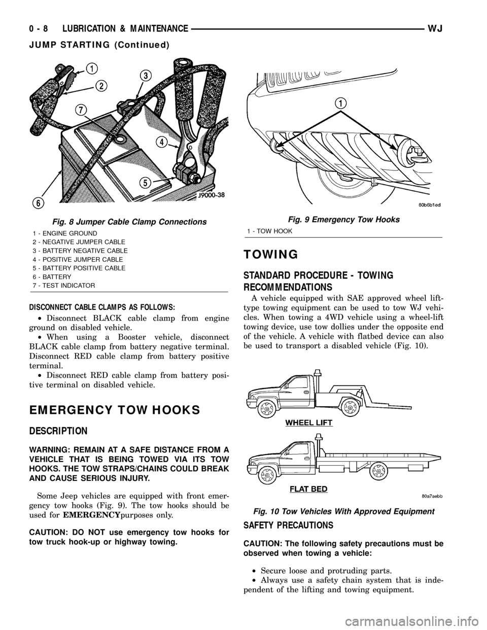
ground cable attaching point as possible (Fig. 8).
(6) Start the engine in the vehicle which has the
booster battery, let the engine idle a few minutes,
then start the engine in the vehicle with the dis-
charged battery.
CAUTION: Do not crank starter motor on disabled
vehicle for more than 15 seconds, starter will over-
heat and could fail.
(7) Allow battery in disabled vehicle to charge to
at least 12.4 volts (75% charge) before attempting to
start engine. If engine does not start within 15 sec-
onds, stop cranking engine and allow starter to cool
(15 min.), before cranking again.
Fig. 7 Correct Vehicle Lifting Locations
WJLUBRICATION & MAINTENANCE 0 - 7
LIFT POINTS (Continued)
Page 19 of 2199
DISCONNECT CABLE CLAMPS AS FOLLOWS:
²Disconnect BLACK cable clamp from engine
ground on disabled vehicle.
²When using a Booster vehicle, disconnect
BLACK cable clamp from battery negative terminal.
Disconnect RED cable clamp from battery positive
terminal.
²Disconnect RED cable clamp from battery posi-
tive terminal on disabled vehicle.
EMERGENCY TOW HOOKS
DESCRIPTION
WARNING: REMAIN AT A SAFE DISTANCE FROM A
VEHICLE THAT IS BEING TOWED VIA ITS TOW
HOOKS. THE TOW STRAPS/CHAINS COULD BREAK
AND CAUSE SERIOUS INJURY.
Some Jeep vehicles are equipped with front emer-
gency tow hooks (Fig. 9). The tow hooks should be
used forEMERGENCYpurposes only.
CAUTION: DO NOT use emergency tow hooks for
tow truck hook-up or highway towing.
TOWING
STANDARD PROCEDURE - TOWING
RECOMMENDATIONS
A vehicle equipped with SAE approved wheel lift-
type towing equipment can be used to tow WJ vehi-
cles. When towing a 4WD vehicle using a wheel-lift
towing device, use tow dollies under the opposite end
of the vehicle. A vehicle with flatbed device can also
be used to transport a disabled vehicle (Fig. 10).
SAFETY PRECAUTIONS
CAUTION: The following safety precautions must be
observed when towing a vehicle:
²Secure loose and protruding parts.
²Always use a safety chain system that is inde-
pendent of the lifting and towing equipment.
Fig. 8 Jumper Cable Clamp Connections
1 - ENGINE GROUND
2 - NEGATIVE JUMPER CABLE
3 - BATTERY NEGATIVE CABLE
4 - POSITIVE JUMPER CABLE
5 - BATTERY POSITIVE CABLE
6 - BATTERY
7 - TEST INDICATOR
Fig. 9 Emergency Tow Hooks
1 - TOW HOOK
Fig. 10 Tow Vehicles With Approved Equipment
0 - 8 LUBRICATION & MAINTENANCEWJ
JUMP STARTING (Continued)
Page 20 of 2199

²Do not allow towing equipment to contact the
disabled vehicle's fuel tank.
²Do not allow anyone under the disabled vehicle
while it is lifted by the towing device.
²Do not allow passengers to ride in a vehicle
being towed.
²Always observe state and local laws regarding
towing regulations.
²Do not tow a vehicle in a manner that could
jeopardize the safety of the operator, pedestrians or
other motorists.
²Do not attach tow chains, T-hooks, or J-hooks to
a bumper, steering linkage, drive shafts or a non-re-
inforced frame hole.
²Do not tow a heavily loaded vehicle. Use a flat-
bed device to transport a loaded vehicle.
TWO-WHEEL-DRIVE VEHICLE TOWING
DaimlerChrysler Corporation recommends that a
vehicle be towed with the rear end lifted, whenever
possible.
WARNING: WHEN TOWING A DISABLED VEHICLE
AND THE DRIVE WHEELS ARE SECURED IN A
WHEEL LIFT OR TOW DOLLIES, ENSURE THE
TRANSMISSION IS IN THE PARK POSITION (AUTO-
MATIC TRANSMISSION) OR A FORWARD DRIVE
GEAR (MANUAL TRANSMISSION).
WARNING: ENSURE VEHICLE IS ON A LEVEL SUR-
FACE OR THE WHEELS ARE BLOCKED TO PRE-
VENT VEHICLE FROM ROLLING.
TWO WHEEL DRIVE TOWING-REAR END LIFTED
CAUTION: Do not use steering column lock to
secure steering wheel during towing operation.
2WD vehicles can be towed with the front wheels
on the surface for extended distances at speeds not
exceeding 48 km/h (30 mph).
(1) Attach wheel lift device to rear wheels.
(2) Place the transmission in neutral.
(3) Raise vehicle to towing position.
(4) Attach safety chains. Route chains so not to
interfere with tail pipe when vehicle is lifted.
(5) Turn the ignition switch to the OFF position to
unlock the steering wheel.
CAUTION: Do not use steering column lock to
secure steering wheel during towing operation.
(6) Secure steering wheel in straight ahead posi-
tion with a clamp device designed for towing.
(7) Place transmission in park.
TWO WHEEL DRIVE TOWING-FRONT END LIFTED
CAUTION: Many vehicles are equipped with air
dams, spoilers, and/or ground effect panels. To
avoid component damage, a wheel-lift towing vehi-
cle or a flat-bed hauling vehicle is recommended.
(1) Attach wheel lift device to rear wheels.
(2) Place the transmission in neutral.
(3) Raise the rear of the vehicle off the ground and
install tow dollies under rear wheels.
(4) Attach wheel lift device to front wheels and
raise vehicle to towing position.
(5) Attach the safety chains.
CAUTION: Do not use steering column lock to
secure steering wheel during towing operation.
(6) Turn the ignition switch to the OFF position to
unlock the steering wheel.
(7) Secure steering wheel in straight ahead posi-
tion with a clamp device designed for towing.
(8) Place transmission in park.
FOUR-WHEEL-DRIVE VEHICLE TOWING
DaimlerChrysler Corporation recommends that a
4WD vehicle be transported on a flat-bed device. A
Wheel-lift device can be used providedthe trailing
wheels are off the ground and positioned in
tow dollies.
WARNING: WHEN TOWING A DISABLED VEHICLE
AND THE DRIVE WHEELS ARE SECURED IN A
WHEEL LIFT OR TOW DOLLIES, ENSURE THE
TRANSMISSION IS IN THE PARK POSITION.
CAUTION: Many vehicles are equipped with air
dams, spoilers, and/or ground effect panels. To
avoid component damage, a wheel-lift towing vehi-
cle or a flat-bed hauling vehicle is recommended.
FOUR WHEEL DRIVE TOWINGÐREAR END LIFTED
WARNING: ENSURE VEHICLE IS ON A LEVEL SUR-
FACE OR THE WHEELS ARE BLOCKED TO PRE-
VENT VEHICLE FROM ROLLING.
(1) Attach wheel lift device to front wheels.
(2) Place the transmission in neutral.
(3) Raise the front of the vehicle off the ground
and install tow dollies under front wheels.
(4) Attach wheel lift device to rear wheels and
raise vehicle to towing position.
(5) Attach safety chains. Route chains so not to
interfere with tail pipe when vehicle is lifted.
WJLUBRICATION & MAINTENANCE 0 - 9
TOWING (Continued)
Page 21 of 2199

(6) Turn the ignition switch to the OFF position to
unlock the steering wheel.
CAUTION: Do not use steering column lock to
secure steering wheel during towing operation.
(7) Secure steering wheel in straight ahead posi-
tion with a clamp device designed for towing.
(8) Place transmission in park.
FOUR WHEEL DRIVE TOWINGÐFRONT END
LIFTED
WARNING: ENSURE VEHICLE IS ON A LEVEL SUR-
FACE OR THE WHEELS ARE BLOCKED TO PRE-
VENT VEHICLE FROM ROLLING.
(1) Attach wheel lift device to rear wheels.(2) Place the transmission in neutral.
(3) Raise the rear of the vehicle off the ground and
install tow dollies under rear wheels.
(4) Attach wheel lift device to front wheels and
raise vehicle to towing position.
(5) Attach the safety chains.
CAUTION: Do not use steering column lock to
secure steering wheel during towing operation.
(6) Turn the ignition switch to the OFF position to
unlock the steering wheel.
(7) Secure steering wheel in straight ahead posi-
tion with a clamp device designed for towing.
(8) Place transmission in park.
0 - 10 LUBRICATION & MAINTENANCEWJ
TOWING (Continued)
Page 32 of 2199

LOWER BALL JOINT
REMOVAL
Ball stud service procedures below require removal
of the hub bearing and axle shaft. Removal and
installation of upper and lower ball studs require the
use of Tool Kit 6289.
(1) Position tools as shown to remove and install
ball stud (Fig. 6).
LOWER CONTROL ARM
DESCRIPTION
The lower suspension arms are hydroformed steel
and use voided oval bushings at one end of the arm.
OPERATION
The bushings provide isolation from the axle. The
arms mount to the unibody frame rail bracket and
the axle brackets. The arm and bushings provide
location and react to loads from the axle.
REMOVAL
(1) Raise the vehicle and support the front axle.
(2) Remove the lower suspension arm nut and bolt
from the axle bracket (Fig. 7).
(3) Remove the nut and bolt from the frame rail
bracket and remove the lower suspension arm (Fig.
7).
INSTALLATION
(1) Position the lower suspension arm in the axle
bracket and frame rail bracket.
NOTE: The end of the arm with the oval bushing
attaches to the axle bracket.
(2) Install the axle bracket bolt and nut finger
tight.
(3) Install the frame rail bracket bolt and nut fin-
ger tight.
(4) Remove support and lower the vehicle.
(5) With the vehicle on the ground tighten the
frame bracket bolt to 156 N´m (115 ft. lbs.). Tighten
the axle bracket nut to 163 N´m (120 ft. lbs.).
(6) Check the alignment if new parts were
installed.
Fig. 6 Lower
1 - SPECIAL TOOL 6289±12
2 - SPECIAL TOOL 6289±4
3 - SPECIAL TOOL 4212F
4 - SPECIAL TOOL 4212F5 - SPECIAL TOOL 6289±1
6 - SPECIAL TOOL 6289±3
WJFRONT 2 - 11
Page 35 of 2199
(6) Install the track bar to the axle bracket and
install the mounting bolt.
NOTE: It may be necessary to pry the axle assem-
bly over to install the track bar bolt.
(7) Remove the hydraulic jack from under the
vehicle.
(8) Tighten all suspension components to proper
torque.
(9) Install the wheel and tire assemblies.
(10) Remove support and lower vehicle.
STABILIZER BAR
DESCRIPTION
The bar extends across the front underside of the
chassis and is mounted to the frame rails. Links are
connected from the bar to the axle brackets. The sta-
bilizer bar and links are isolated by rubber bushings.
OPERATION
The stabilizer bar is used to control vehicle body
roll during turns. The spring steel bar helps to con-
trol the vehicle body in relationship to the suspen-
sion.
REMOVAL
(1) Raise and support the vehicle.
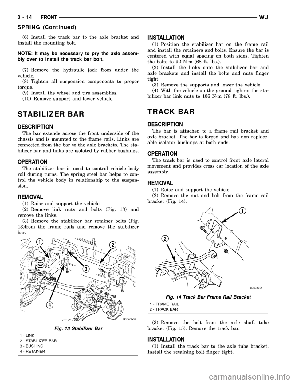
(2) Remove link nuts and bolts (Fig. 13) and
remove the links.
(3) Remove the stabilizer bar retainer bolts (Fig.
13)from the frame rails and remove the stabilizer
bar.
INSTALLATION
(1) Position the stabilizer bar on the frame rail
and install the retainers and bolts. Ensure the bar is
centered with equal spacing on both sides. Tighten
the bolts to 92 N´m (68 ft. lbs.).
(2) Install the links onto the stabilizer bar and
axle brackets and install the bolts and nuts finger
tight.
(3) Remove the supports and lower the vehicle.
(4) With the vehicle on the ground tighten the sta-
bilizer bar link nuts to 106 N´m (78 ft. lbs.).
TRACK BAR
DESCRIPTION
The bar is attached to a frame rail bracket and
axle bracket. The bar is forged and has non replace-
able isolator bushings at both ends.
OPERATION
The track bar is used to control front axle lateral
movement and provides cross car location of the axle
assembly.
REMOVAL
(1) Raise and support the vehicle.
(2) Remove the nut and bolt from the frame rail
bracket (Fig. 14).
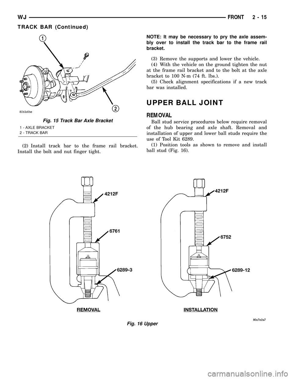
(3) Remove the bolt from the axle shaft tube
bracket (Fig. 15). Remove the track bar.
INSTALLATION
(1) Install the track bar to the axle tube bracket.
Install the retaining bolt finger tight.
Fig. 13 Stabilizer Bar
1 - LINK
2 - STABILIZER BAR
3 - BUSHING
4 - RETAINER
Fig. 14 Track Bar Frame Rail Bracket
1 - FRAME RAIL
2 - TRACK BAR
2 - 14 FRONTWJ
SPRING (Continued)
Page 36 of 2199
(2) Install track bar to the frame rail bracket.
Install the bolt and nut finger tight.NOTE: It may be necessary to pry the axle assem-
bly over to install the track bar to the frame rail
bracket.
(3) Remove the supports and lower the vehicle.
(4) With the vehicle on the ground tighten the nut
at the frame rail bracket and to the bolt at the axle
bracket to 100 N´m (74 ft. lbs.).
(5) Check alignment specifications if a new track
bar was installed.
UPPER BALL JOINT
REMOVAL
Ball stud service procedures below require removal
of the hub bearing and axle shaft. Removal and
installation of upper and lower ball studs require the
use of Tool Kit 6289.
(1) Position tools as shown to remove and install
ball stud (Fig. 16).
Fig. 16 Upper
Fig. 15 Track Bar Axle Bracket
1 - AXLE BRACKET
2 - TRACK BAR
WJFRONT 2 - 15
TRACK BAR (Continued)
Page 37 of 2199

UPPER CONTROL ARM
DESCRIPTION
The upper suspension arms are hydroformed steel
and use rubber bushings at each end of the arm.
OPERATION
The arms mount to the unibody frame rail bracket
and the axle brackets. The arm and bushings provide
location and react to loads from the axle. The bush-
ings provide isolation from the axle.
REMOVAL
(1) Raise vehicle and support the axle.
(2) Remove the upper suspension arm mounting
nut and bolt (Fig. 17) from the axle bracket.(3) Remove the nut and bolt (Fig. 17) at the frame
rail and remove the upper suspension arm.
INSTALLATION
(1) Position the upper suspension arm at the axle
and frame rail.
(2) Install the bolts and finger tighten the nuts.
(3) Remove the supports and lower the vehicle.
(4) With the vehicle on the ground tighten the axle
bracket nut and the frame bracket bolt to 61 N´m (45
ft. lbs.).
(5) Check the alignment if new parts were
installed.
Fig. 17 Upper Suspension Arm
1 - UPPER SUSPENSION ARM
2 - FRAME BOLT
3 - AXLE BOLT
2 - 16 FRONTWJ
Page 40 of 2199
SPECIAL TOOLS
REAR SUSPENSION
LOWER CONTROL ARM
DESCRIPTION
The lower suspension arms are hydroformed steel
and use voided oval bushings at each end of the arm.
OPERATION
The bushings provide isolation from the axle. The
arms mount to the unibody frame rail bracket and
the axle brackets. The arm and bushings provide
location and react to loads.
REMOVAL
(1) Raise the vehicle and support the rear axle.
(2) Remove the lower suspension arm nut and bolt
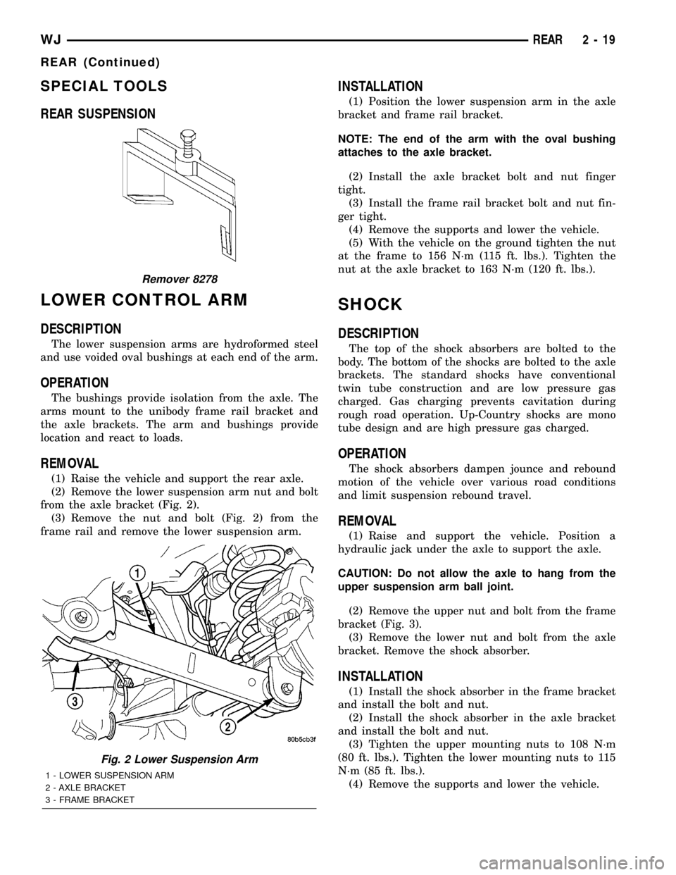
from the axle bracket (Fig. 2).
(3) Remove the nut and bolt (Fig. 2) from the
frame rail and remove the lower suspension arm.
INSTALLATION
(1) Position the lower suspension arm in the axle
bracket and frame rail bracket.
NOTE: The end of the arm with the oval bushing
attaches to the axle bracket.
(2) Install the axle bracket bolt and nut finger
tight.
(3) Install the frame rail bracket bolt and nut fin-
ger tight.
(4) Remove the supports and lower the vehicle.
(5) With the vehicle on the ground tighten the nut
at the frame to 156 N´m (115 ft. lbs.). Tighten the
nut at the axle bracket to 163 N´m (120 ft. lbs.).
SHOCK
DESCRIPTION
The top of the shock absorbers are bolted to the
body. The bottom of the shocks are bolted to the axle
brackets. The standard shocks have conventional
twin tube construction and are low pressure gas
charged. Gas charging prevents cavitation during
rough road operation. Up-Country shocks are mono
tube design and are high pressure gas charged.
OPERATION
The shock absorbers dampen jounce and rebound
motion of the vehicle over various road conditions
and limit suspension rebound travel.
REMOVAL
(1) Raise and support the vehicle. Position a
hydraulic jack under the axle to support the axle.
CAUTION: Do not allow the axle to hang from the
upper suspension arm ball joint.
(2) Remove the upper nut and bolt from the frame
bracket (Fig. 3).
(3) Remove the lower nut and bolt from the axle
bracket. Remove the shock absorber.
INSTALLATION
(1) Install the shock absorber in the frame bracket
and install the bolt and nut.
(2) Install the shock absorber in the axle bracket
and install the bolt and nut.
(3) Tighten the upper mounting nuts to 108 N´m
(80 ft. lbs.). Tighten the lower mounting nuts to 115
N´m (85 ft. lbs.).
(4) Remove the supports and lower the vehicle.
Remover 8278
Fig. 2 Lower Suspension Arm
1 - LOWER SUSPENSION ARM
2 - AXLE BRACKET
3 - FRAME BRACKET
WJREAR 2 - 19
REAR (Continued)
Page 61 of 2199
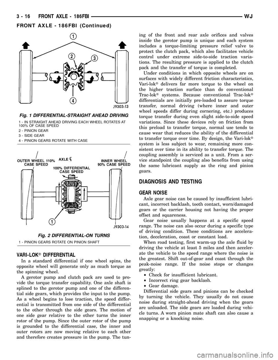
VARI-LOKTDIFFERENTIAL
In a standard differential if one wheel spins, the
opposite wheel will generate only as much torque as
the spinning wheel.
A gerotor pump and clutch pack are used to pro-
vide the torque transfer capability. One axle shaft is
splined to the gerotor pump and one of the differen-
tial side gears, which provides the input to the pump.
As a wheel begins to lose traction, the speed differ-
ential is transmitted from one side of the differential
to the other through the side gears. The motion of
one side gear relative to the other turns the inner
rotor of the pump. Since the outer rotor of the pump
is grounded to the differential case, the inner and
outer rotors are now moving relative to each other
and therefore creates pressure in the pump. The tun-ing of the front and rear axle orifices and valves
inside the gerotor pump is unique and each system
includes a torque-limiting pressure relief valve to
protect the clutch pack, which also facilitates vehicle
control under extreme side-to-side traction varia-
tions. The resulting pressure is applied to the clutch
pack and the transfer of torque is completed.
Under conditions in which opposite wheels are on
surfaces with widely different friction characteristics,
Vari-loktdelivers far more torque to the wheel on
the higher traction surface than do conventional
Trac-loktsystems. Because conventional Trac-lokt
differentials are initially pre-loaded to assure torque
transfer, normal driving (where inner and outer
wheel speeds differ during cornering, etc.) produces
torque transfer during even slight side-to-side speed
variations. Since these devices rely on friction from
this preload to transfer torque, normal use tends to
cause wear that reduces the ability of the differential
to transfer torque over time. By design, the Vari-lokt
system is less subject to wear, remaining more con-
sistent over time in its ability to transfer torque. The
coupling assembly is serviced as a unit. From a ser-
vice standpoint the coupling also benefits from using
the same lubricant supply as the ring and pinion
gears.
DIAGNOSIS AND TESTING
GEAR NOISE
Axle gear noise can be caused by insufficient lubri-
cant, incorrect backlash, tooth contact, worn/damaged
gears or the carrier housing not having the proper
offset and squareness.
Gear noise usually happens at a specific speed
range. The noise can also occur during a specific type
of driving condition. These conditions are accelera-
tion, deceleration, coast or constant load.
When road testing, first warm-up the axle fluid by
driving the vehicle at least 5 miles and then acceler-
ate the vehicle to the speed range where the noise is
the greatest. Shift out-of-gear and coast through the
peak-noise range. If the noise stops or changes
greatly:
²Check for insufficient lubricant.
²Incorrect ring gear backlash.
²Gear damage.
Differential side gears and pinions can be checked
by turning the vehicle. They usually do not cause
noise during straight-ahead driving when the gears
are unloaded. The side gears are loaded during vehi-
cle turns. A worn pinion mate shaft can also cause a
snapping or a knocking noise.
Fig. 1 DIFFERENTIAL-STRAIGHT AHEAD DRIVING
1 - IN STRAIGHT AHEAD DRIVING EACH WHEEL ROTATES AT
100% OF CASE SPEED
2 - PINION GEAR
3 - SIDE GEAR
4 - PINION GEARS ROTATE WITH CASE
Fig. 2 DIFFERENTIAL-ON TURNS
1 - PINION GEARS ROTATE ON PINION SHAFT
3 - 16 FRONT AXLE - 186FBIWJ
FRONT AXLE - 186FBI (Continued)