ground JEEP GRAND CHEROKEE 2002 WJ / 2.G User Guide
[x] Cancel search | Manufacturer: JEEP, Model Year: 2002, Model line: GRAND CHEROKEE, Model: JEEP GRAND CHEROKEE 2002 WJ / 2.GPages: 2199, PDF Size: 76.01 MB
Page 65 of 2199
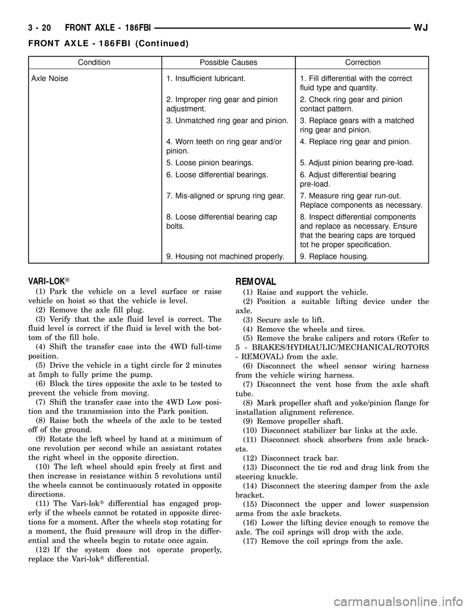
Condition Possible Causes Correction
Axle Noise 1. Insufficient lubricant. 1. Fill differential with the correct
fluid type and quantity.
2. Improper ring gear and pinion
adjustment.2. Check ring gear and pinion
contact pattern.
3. Unmatched ring gear and pinion. 3. Replace gears with a matched
ring gear and pinion.
4. Worn teeth on ring gear and/or
pinion.4. Replace ring gear and pinion.
5. Loose pinion bearings. 5. Adjust pinion bearing pre-load.
6. Loose differential bearings. 6. Adjust differential bearing
pre-load.
7. Mis-aligned or sprung ring gear. 7. Measure ring gear run-out.
Replace components as necessary.
8. Loose differential bearing cap
bolts.8. Inspect differential components
and replace as necessary. Ensure
that the bearing caps are torqued
tot he proper specification.
9. Housing not machined properly. 9. Replace housing.
VARI-LOKT
(1) Park the vehicle on a level surface or raise
vehicle on hoist so that the vehicle is level.
(2) Remove the axle fill plug.
(3) Verify that the axle fluid level is correct. The
fluid level is correct if the fluid is level with the bot-
tom of the fill hole.
(4) Shift the transfer case into the 4WD full-time
position.
(5) Drive the vehicle in a tight circle for 2 minutes
at 5mph to fully prime the pump.
(6) Block the tires opposite the axle to be tested to
prevent the vehicle from moving.
(7) Shift the transfer case into the 4WD Low posi-
tion and the transmission into the Park position.
(8) Raise both the wheels of the axle to be tested
off of the ground.
(9) Rotate the left wheel by hand at a minimum of
one revolution per second while an assistant rotates
the right wheel in the opposite direction.
(10) The left wheel should spin freely at first and
then increase in resistance within 5 revolutions until
the wheels cannot be continuously rotated in opposite
directions.
(11) The Vari-loktdifferential has engaged prop-
erly if the wheels cannot be rotated in opposite direc-
tions for a moment. After the wheels stop rotating for
a moment, the fluid pressure will drop in the differ-
ential and the wheels begin to rotate once again.
(12) If the system does not operate properly,
replace the Vari-loktdifferential.
REMOVAL
(1) Raise and support the vehicle.
(2) Position a suitable lifting device under the
axle.
(3) Secure axle to lift.
(4) Remove the wheels and tires.
(5) Remove the brake calipers and rotors (Refer to
5 - BRAKES/HYDRAULIC/MECHANICAL/ROTORS
- REMOVAL) from the axle.
(6) Disconnect the wheel sensor wiring harness
from the vehicle wiring harness.
(7) Disconnect the vent hose from the axle shaft
tube.
(8) Mark propeller shaft and yoke/pinion flange for
installation alignment reference.
(9) Remove propeller shaft.
(10) Disconnect stabilizer bar links at the axle.
(11) Disconnect shock absorbers from axle brack-
ets.
(12) Disconnect track bar.
(13) Disconnect the tie rod and drag link from the
steering knuckle.
(14) Disconnect the steering damper from the axle
bracket.
(15) Disconnect the upper and lower suspension
arms from the axle brackets.
(16) Lower the lifting device enough to remove the
axle. The coil springs will drop with the axle.
(17) Remove the coil springs from the axle.
3 - 20 FRONT AXLE - 186FBIWJ
FRONT AXLE - 186FBI (Continued)
Page 100 of 2199
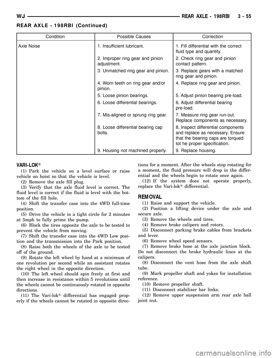
Condition Possible Causes Correction
Axle Noise 1. Insufficient lubricant. 1. Fill differential with the correct
fluid type and quantity.
2. Improper ring gear and pinion
adjustment.2. Check ring gear and pinion
contact pattern.
3. Unmatched ring gear and pinion. 3. Replace gears with a matched
ring gear and pinion.
4. Worn teeth on ring gear and/or
pinion.4. Replace ring gear and pinion.
5. Loose pinion bearings. 5. Adjust pinion bearing pre-load.
6. Loose differential bearings. 6. Adjust differential bearing
pre-load.
7. Mis-aligned or sprung ring gear. 7. Measure ring gear run-out.
Replace components as necessary.
8. Loose differential bearing cap
bolts.8. Inspect differential components
and replace as necessary. Ensure
that the bearing caps are torqued
tot he proper specification.
9. Housing not machined properly. 9. Replace housing.
VARI-LOKT
(1) Park the vehicle on a level surface or raise
vehicle on hoist so that the vehicle is level.
(2) Remove the axle fill plug.
(3) Verify that the axle fluid level is correct. The
fluid level is correct if the fluid is level with the bot-
tom of the fill hole.
(4) Shift the transfer case into the 4WD full-time
position.
(5) Drive the vehicle in a tight circle for 2 minutes
at 5mph to fully prime the pump.
(6) Block the tires opposite the axle to be tested to
prevent the vehicle from moving.
(7) Shift the transfer case into the 4WD Low posi-
tion and the transmission into the Park position.
(8) Raise both the wheels of the axle to be tested
off of the ground.
(9) Rotate the left wheel by hand at a minimum of
one revolution per second while an assistant rotates
the right wheel in the opposite direction.
(10) The left wheel should spin freely at first and
then increase in resistance within 5 revolutions until
the wheels cannot be continuously rotated in opposite
directions.
(11) The Vari-loktdifferential has engaged prop-
erly if the wheels cannot be rotated in opposite direc-tions for a moment. After the wheels stop rotating for
a moment, the fluid pressure will drop in the differ-
ential and the wheels begin to rotate once again.
(12) If the system does not operate properly,
replace the Vari-loktdifferential.
REMOVAL
(1) Raise and support the vehicle.
(2) Position a lifting device under the axle and
secure axle.
(3) Remove the wheels and tires.
(4) Remove brake calipers and rotors.
(5) Disconnect parking brake cables from brackets
and lever.
(6) Remove wheel speed sensors.
(7) Remove brake hose at the axle junction block.
Do not disconnect the brake hydraulic lines at the
calipers.
(8) Disconnect the vent hose from the axle shaft
tube.
(9) Mark propeller shaft and yokes for installation
reference.
(10) Remove propeller shaft.
(11) Disconnect stabilizer bar links.
(12) Remove upper suspension arm rear axle ball
joint nut.
WJREAR AXLE - 198RBI 3 - 55
REAR AXLE - 198RBI (Continued)
Page 124 of 2199
(12) Install cover and tighten bolts in a criss-cross
pattern to 41 N´m (30 ft. lbs.).
(13) Refill the differential with Mopar Hypoid
Gear Lubricant or equivalent to bottom of the fill
plug hole.
(14) Install fill hole plug.
(15) Remove support and lower the vehicle.
DIFFERENTIAL-TRAC-LOC
DIAGNOSIS AND TESTING
The most common problem is a chatter noise when
turning corners. Before removing the unit for repair,
drain, flush and refill the axle with the specified
lubricant. A container of Mopar Trac-loktLubricant
(friction modifier) should be added after repair ser-
vice or during a lubricant change.
After changing the lubricant, drive the vehicle and
make 10 to 12 slow, figure-eight turns. This maneu-
ver will pump lubricant through the clutches. This
will correct the condition in most instances. If the
chatter persists, clutch damage could have occurred.
DIFFERENTIAL TEST
The differential can be tested without removing the
differential case by measuring rotating torque. Make
sure brakes are not dragging during this measure-
ment.
(1) Place blocks in front and rear of both front
wheels.
(2) Raise one rear wheel until it is completely off
the ground.
(3) Engine off, transmission in neutral, and park-
ing brake off.
(4) Remove wheel and bolt Special Tool 6790 or
equivalent tool to studs.
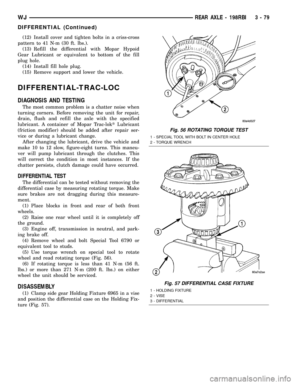
(5) Use torque wrench on special tool to rotate
wheel and read rotating torque (Fig. 56).
(6) If rotating torque is less than 41 N´m (56 ft.
lbs.) or more than 271 N´m (200 ft. lbs.) on either
wheel the unit should be serviced.
DISASSEMBLY
(1) Clamp side gear Holding Fixture 6965 in a vise
and position the differential case on the Holding Fix-
ture (Fig. 57).
Fig. 56 ROTATING TORQUE TEST
1 - SPECIAL TOOL WITH BOLT IN CENTER HOLE
2 - TORQUE WRENCH
Fig. 57 DIFFERENTIAL CASE FIXTURE
1 - HOLDING FIXTURE
2 - VISE
3 - DIFFERENTIAL
WJREAR AXLE - 198RBI 3 - 79
DIFFERENTIAL (Continued)
Page 136 of 2199
TRAC-LOKTDIFFERENTIAL
The differential clutches are engaged by two con-
current forces. The first being the preload force
exerted through Belleville spring washers within the
clutch packs. The second is the separating forces gen-
erated by the side gears as torque is applied through
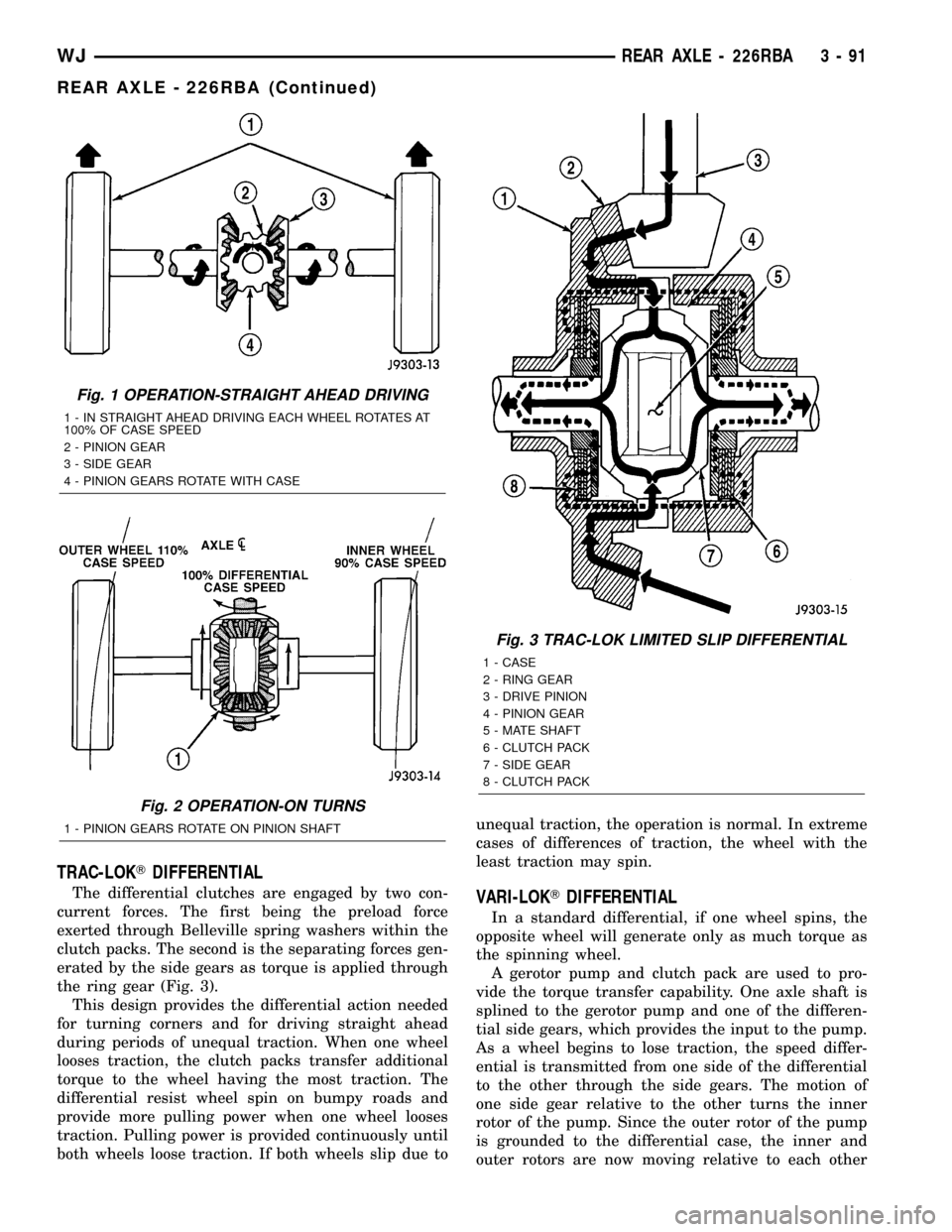
the ring gear (Fig. 3).
This design provides the differential action needed
for turning corners and for driving straight ahead
during periods of unequal traction. When one wheel
looses traction, the clutch packs transfer additional
torque to the wheel having the most traction. The
differential resist wheel spin on bumpy roads and
provide more pulling power when one wheel looses
traction. Pulling power is provided continuously until
both wheels loose traction. If both wheels slip due tounequal traction, the operation is normal. In extreme
cases of differences of traction, the wheel with the
least traction may spin.VARI-LOKTDIFFERENTIAL
In a standard differential, if one wheel spins, the
opposite wheel will generate only as much torque as
the spinning wheel.
A gerotor pump and clutch pack are used to pro-
vide the torque transfer capability. One axle shaft is
splined to the gerotor pump and one of the differen-
tial side gears, which provides the input to the pump.
As a wheel begins to lose traction, the speed differ-
ential is transmitted from one side of the differential
to the other through the side gears. The motion of
one side gear relative to the other turns the inner
rotor of the pump. Since the outer rotor of the pump
is grounded to the differential case, the inner and
outer rotors are now moving relative to each other
Fig. 1 OPERATION-STRAIGHT AHEAD DRIVING
1 - IN STRAIGHT AHEAD DRIVING EACH WHEEL ROTATES AT
100% OF CASE SPEED
2 - PINION GEAR
3 - SIDE GEAR
4 - PINION GEARS ROTATE WITH CASE
Fig. 2 OPERATION-ON TURNS
1 - PINION GEARS ROTATE ON PINION SHAFT
Fig. 3 TRAC-LOK LIMITED SLIP DIFFERENTIAL
1 - CASE
2 - RING GEAR
3 - DRIVE PINION
4 - PINION GEAR
5 - MATE SHAFT
6 - CLUTCH PACK
7 - SIDE GEAR
8 - CLUTCH PACK
WJREAR AXLE - 226RBA 3 - 91
REAR AXLE - 226RBA (Continued)
Page 140 of 2199
Condition Possible Causes Correction
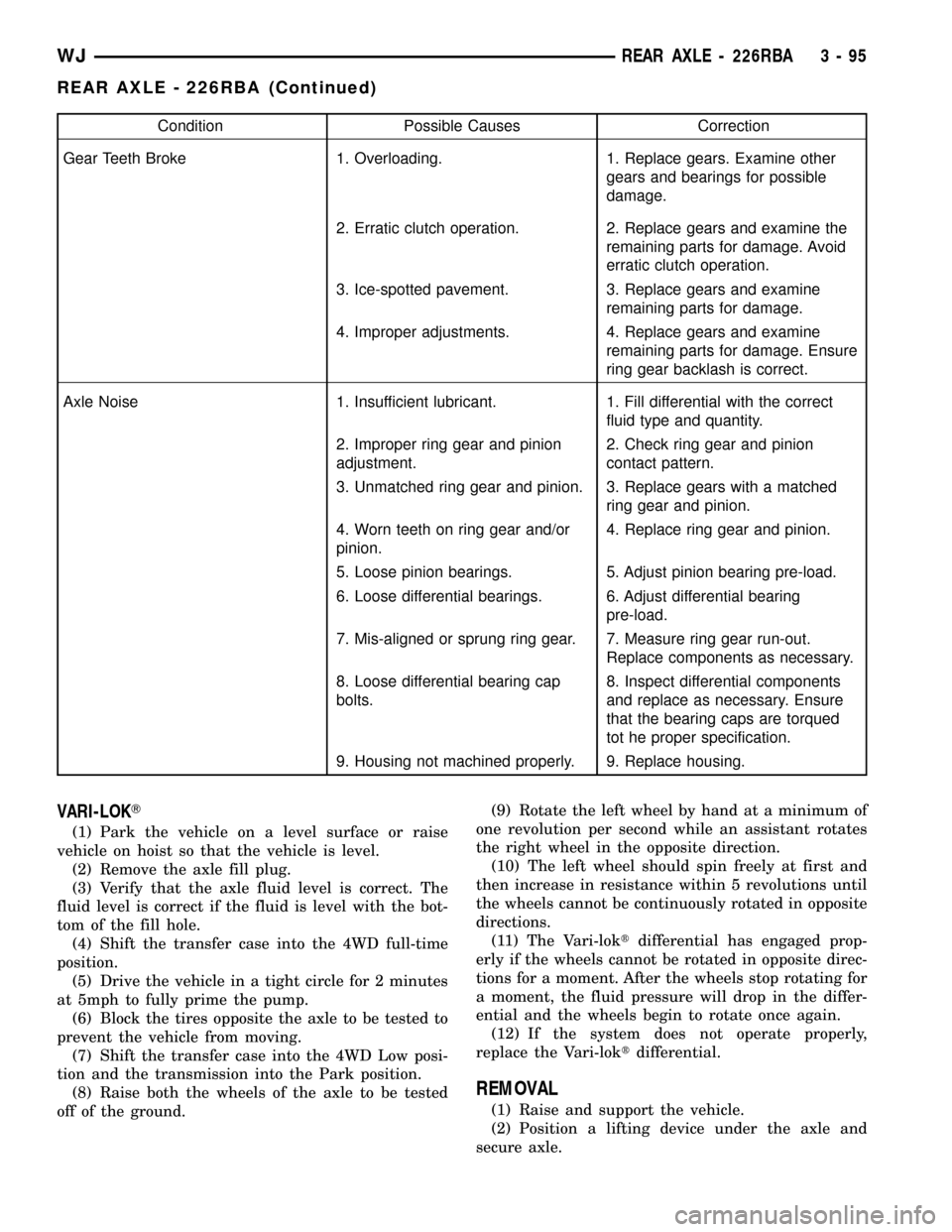
Gear Teeth Broke 1. Overloading. 1. Replace gears. Examine other
gears and bearings for possible
damage.
2. Erratic clutch operation. 2. Replace gears and examine the
remaining parts for damage. Avoid
erratic clutch operation.
3. Ice-spotted pavement. 3. Replace gears and examine
remaining parts for damage.
4. Improper adjustments. 4. Replace gears and examine
remaining parts for damage. Ensure
ring gear backlash is correct.
Axle Noise 1. Insufficient lubricant. 1. Fill differential with the correct
fluid type and quantity.
2. Improper ring gear and pinion
adjustment.2. Check ring gear and pinion
contact pattern.
3. Unmatched ring gear and pinion. 3. Replace gears with a matched
ring gear and pinion.
4. Worn teeth on ring gear and/or
pinion.4. Replace ring gear and pinion.
5. Loose pinion bearings. 5. Adjust pinion bearing pre-load.
6. Loose differential bearings. 6. Adjust differential bearing
pre-load.
7. Mis-aligned or sprung ring gear. 7. Measure ring gear run-out.
Replace components as necessary.
8. Loose differential bearing cap
bolts.8. Inspect differential components
and replace as necessary. Ensure
that the bearing caps are torqued
tot he proper specification.
9. Housing not machined properly. 9. Replace housing.
VARI-LOKT
(1) Park the vehicle on a level surface or raise
vehicle on hoist so that the vehicle is level.
(2) Remove the axle fill plug.
(3) Verify that the axle fluid level is correct. The
fluid level is correct if the fluid is level with the bot-
tom of the fill hole.
(4) Shift the transfer case into the 4WD full-time
position.
(5) Drive the vehicle in a tight circle for 2 minutes
at 5mph to fully prime the pump.
(6) Block the tires opposite the axle to be tested to
prevent the vehicle from moving.
(7) Shift the transfer case into the 4WD Low posi-
tion and the transmission into the Park position.
(8) Raise both the wheels of the axle to be tested
off of the ground.(9) Rotate the left wheel by hand at a minimum of
one revolution per second while an assistant rotates
the right wheel in the opposite direction.
(10) The left wheel should spin freely at first and
then increase in resistance within 5 revolutions until
the wheels cannot be continuously rotated in opposite
directions.
(11) The Vari-loktdifferential has engaged prop-
erly if the wheels cannot be rotated in opposite direc-
tions for a moment. After the wheels stop rotating for
a moment, the fluid pressure will drop in the differ-
ential and the wheels begin to rotate once again.
(12) If the system does not operate properly,
replace the Vari-loktdifferential.
REMOVAL
(1) Raise and support the vehicle.
(2) Position a lifting device under the axle and
secure axle.
WJREAR AXLE - 226RBA 3 - 95
REAR AXLE - 226RBA (Continued)
Page 164 of 2199
(12) Install cover and tighten bolts in a criss-cross
pattern to 41 N´m (30 ft. lbs.).
(13) Refill the differential with Mopar Hypoid
Gear Lubricant or equivalent to bottom of the fill
plug hole.
(14) Install fill hole plug.
(15) Remove support and lower the vehicle.
DIFFERENTIAL - TRAC-LOK
DIAGNOSIS AND TESTING
The most common problem is a chatter noise when
turning corners. Before removing the unit for repair,
drain, flush and refill the axle with the specified
lubricant. A container of Mopar Trac-loktLubricant
(friction modifier) should be added after repair ser-
vice or during a lubricant change.
After changing the lubricant, drive the vehicle and
make 10 to 12 slow, figure-eight turns. This maneu-
ver will pump lubricant through the clutches. This
will correct the condition in most instances. If the
chatter persists, clutch damage could have occurred.
DIFFERENTIAL TEST
The differential can be tested without removing the
differential case by measuring rotating torque. Make
sure brakes are not dragging during this measure-
ment.
(1) Place blocks in front and rear of both front
wheels.
(2) Raise one rear wheel until it is completely off
the ground.
(3) Engine off, transmission in neutral, and park-
ing brake off.
(4) Remove wheel and bolt Special Tool 6790 or
equivalent tool to studs.
(5) Use torque wrench on special tool to rotate
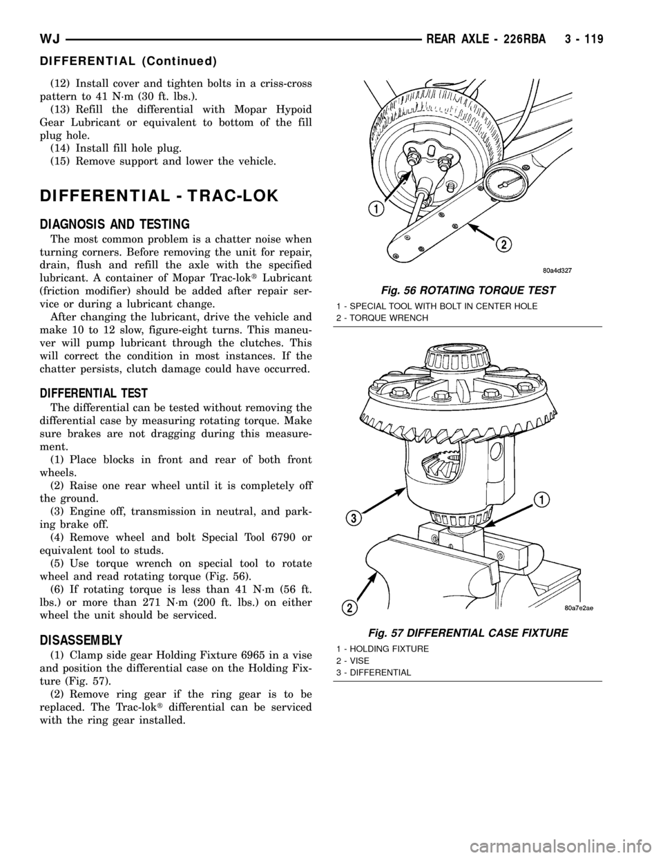
wheel and read rotating torque (Fig. 56).
(6) If rotating torque is less than 41 N´m (56 ft.
lbs.) or more than 271 N´m (200 ft. lbs.) on either
wheel the unit should be serviced.
DISASSEMBLY
(1) Clamp side gear Holding Fixture 6965 in a vise
and position the differential case on the Holding Fix-
ture (Fig. 57).
(2) Remove ring gear if the ring gear is to be
replaced. The Trac-loktdifferential can be serviced
with the ring gear installed.
Fig. 56 ROTATING TORQUE TEST
1 - SPECIAL TOOL WITH BOLT IN CENTER HOLE
2 - TORQUE WRENCH
Fig. 57 DIFFERENTIAL CASE FIXTURE
1 - HOLDING FIXTURE
2 - VISE
3 - DIFFERENTIAL
WJREAR AXLE - 226RBA 3 - 119
DIFFERENTIAL (Continued)
Page 231 of 2199
CONDITION POSSIBLE CAUSES CORRECTION
7. Water pump impeller loose on
shaft.7. Check water pump and replace as
necessary. (Refer to 7 - COOLING/ENGINE/
WATER PUMP - DIAGNOSIS AND
TESTING).
8. Loose accessory drive belt. (water
pump slipping)8. (Refer to 7 - COOLING/ACCESSORY
DRIVE/DRIVE BELTS - DIAGNOSIS AND
TESTING). Check and correct as necessary.
9. Air leak on the suction side of the
water pump allows air to build up in
cooling system causing thermostat
to open late.9. Locate leak and repair as necessary.
PRESSURE CAP IS
BLOWING OFF STEAM
AND/OR COOLANT TO
COOLANT TANK.
TEMPERATURE GAUGE
READING MAY BE
ABOVE NORMAL BUT
NOT HIGH. COOLANT
LEVEL MAY BE HIGH IN
COOLANT RESERVE/
OVERFLOW TANK1. Pressure relief valve in radiator
cap is defective.1. Check condition of radiator cap and cap
seals. (Refer to 7 - COOLING/ENGINE/
RADIATOR PRESSURE CAP - DIAGNOSIS
AND TESTING). Replace cap as necessary.
COOLANT LOSS TO THE
GROUND WITHOUT
PRESSURE CAP
BLOWOFF. GAUGE
READING HIGH OR HOT1. Coolant leaks in radiator, cooling
system hoses, water pump or
engine.1. Pressure test and repair as necessary.
(Refer to 7 - COOLING - DIAGNOSIS AND
TESTING).
DETONATION OR
PRE-IGNITION (NOT
CAUSED BY IGNITION
SYSTEM). GAUGE MAY
OR MAY NOT BE
READING HIGH1. Engine overheating. 1. Check reason for overheating and repair
as necessary.
2. Freeze point of coolant not
correct. Mixture is too rich or too
lean.2. Check coolant concentration. (Refer to 7 -
COOLING/ENGINE/COOLANT -
DESCRIPTION) and adjust ratio as required.
HOSE OR HOSES
COLLAPSE WHILE
ENGINE IS RUNNING1. Vacuum created in cooling system
on engine cool-down is not being
relieved through coolant reserve/
overflow system.1. (a) Radiator cap relief valve stuck. (Refer
to 7 - COOLING/ENGINE/RADIATOR
PRESSURE CAP - DIAGNOSIS AND
TESTING). Replace if necessary
(b) Hose between coolant reserve/overflow
tank and radiator is kinked. Repair as
necessary.
(c) Vent at coolant reserve/overflow tank is
plugged. Clean vent and repair as necessary.
(d) Reserve/overflow tank is internally
blocked or plugged. Check for blockage and
repair as necessary.
7 - 8 COOLINGWJ
COOLING (Continued)
Page 253 of 2199
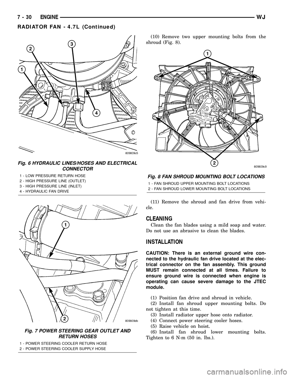
(10) Remove two upper mounting bolts from the
shroud (Fig. 8).
(11) Remove the shroud and fan drive from vehi-
cle.
CLEANING
Clean the fan blades using a mild soap and water.
Do not use an abrasive to clean the blades.
INSTALLATION
CAUTION: There is an external ground wire con-
nected to the hydraulic fan drive located at the elec-
trical connector on the fan assembly. This ground
MUST remain connected at all times. Failure to
ensure ground wire is connected when engine is
operating can cause severe damage to the JTEC
module.
(1) Position fan drive and shroud in vehicle.
(2) Install fan shroud upper mounting bolts. Do
not tighten at this time.
(3) Install radiator upper hose onto radiator.
(4) Connect power steering cooler hoses.
(5) Raise vehicle on hoist.
(6) Install fan shroud lower mounting bolts.
Tighten to 6 N´m (50 in. lbs.).
Fig. 6 HYDRAULIC LINES/HOSES AND ELECTRICAL
CONNECTOR
1 - LOW PRESSURE RETURN HOSE
2 - HIGH PRESSURE LINE (OUTLET)
3 - HIGH PRESSURE LINE (INLET)
4 - HYDRAULIC FAN DRIVE
Fig. 7 POWER STEERING GEAR OUTLET AND
RETURN HOSES
1 - POWER STEERING COOLER RETURN HOSE
2 - POWER STEERING COOLER SUPPLY HOSE
Fig. 8 FAN SHROUD MOUNTING BOLT LOCATIONS
1 - FAN SHROUD UPPER MOUNTING BOLT LOCATIONS
2 - FAN SHROUD LOWER MOUNTING BOLT LOCATIONS
7 - 30 ENGINEWJ
RADIATOR FAN - 4.7L (Continued)
Page 256 of 2199
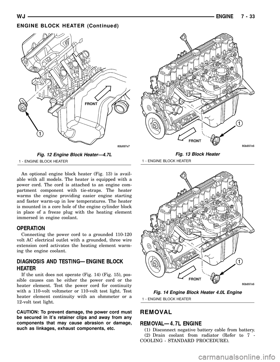
An optional engine block heater (Fig. 13) is avail-
able with all models. The heater is equipped with a
power cord. The cord is attached to an engine com-
partment component with tie-straps. The heater
warms the engine providing easier engine starting
and faster warm-up in low temperatures. The heater
is mounted in a core hole of the engine cylinder block
in place of a freeze plug with the heating element
immersed in engine coolant.
OPERATION
Connecting the power cord to a grounded 110-120
volt AC electrical outlet with a grounded, three wire
extension cord activates the heating element warm-
ing the engine coolant.
DIAGNOSIS AND TESTINGÐENGINE BLOCK
HEATER
If the unit does not operate (Fig. 14) (Fig. 15), pos-
sible causes can be either the power cord or the
heater element. Test the power cord for continuity
with a 110-volt voltmeter or 110-volt test light. Test
heater element continuity with an ohmmeter or a
12-volt test light.
CAUTION: To prevent damage, the power cord must
be secured in it's retainer clips and away from any
components that may cause abrasion or damage,
such as linkages, exhaust components, etc.
REMOVAL
REMOVALÐ4.7L ENGINE
(1) Disconnect negative battery cable from battery.
(2) Drain coolant from radiator (Refer to 7 -
COOLING - STANDARD PROCEDURE).
Fig. 12 Engine Block HeaterÐ4.7L
1 - ENGINE BLOCK HEATER
Fig. 13 Block Heater
1 - ENGINE BLOCK HEATER
Fig. 14 Engine Block Heater 4.0L Engine
1 - ENGINE BLOCK HEATER
WJENGINE 7 - 33
ENGINE BLOCK HEATER (Continued)
Page 258 of 2199
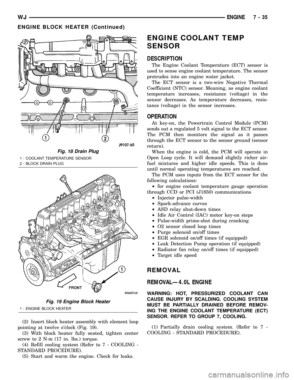
(2) Insert block heater assembly with element loop
pointing at twelve o'clock (Fig. 19).
(3) With block heater fully seated, tighten center
screw to 2 N´m (17 in. lbs.) torque.
(4) Refill cooling system (Refer to 7 - COOLING -
STANDARD PROCEDURE).
(5) Start and warm the engine. Check for leaks.
ENGINE COOLANT TEMP
SENSOR
DESCRIPTION
The Engine Coolant Temperature (ECT) sensor is
used to sense engine coolant temperature. The sensor
protrudes into an engine water jacket.
The ECT sensor is a two-wire Negative Thermal
Coefficient (NTC) sensor. Meaning, as engine coolant
temperature increases, resistance (voltage) in the
sensor decreases. As temperature decreases, resis-
tance (voltage) in the sensor increases.
OPERATION
At key-on, the Powertrain Control Module (PCM)
sends out a regulated 5 volt signal to the ECT sensor.
The PCM then monitors the signal as it passes
through the ECT sensor to the sensor ground (sensor
return).
When the engine is cold, the PCM will operate in
Open Loop cycle. It will demand slightly richer air-
fuel mixtures and higher idle speeds. This is done
until normal operating temperatures are reached.
The PCM uses inputs from the ECT sensor for the
following calculations:
²for engine coolant temperature gauge operation
through CCD or PCI (J1850) communications
²Injector pulse-width
²Spark-advance curves
²ASD relay shut-down times
²Idle Air Control (IAC) motor key-on steps
²Pulse-width prime-shot during cranking
²O2 sensor closed loop times
²Purge solenoid on/off times
²EGR solenoid on/off times (if equipped)
²Leak Detection Pump operation (if equipped)
²Radiator fan relay on/off times (if equipped)
²Target idle speed
REMOVAL
REMOVALÐ4.0L ENGINE
WARNING: HOT, PRESSURIZED COOLANT CAN
CAUSE INJURY BY SCALDING. COOLING SYSTEM
MUST BE PARTIALLY DRAINED BEFORE REMOV-
ING THE ENGINE COOLANT TEMPERATURE (ECT)
SENSOR. REFER TO GROUP 7, COOLING.
(1) Partially drain cooling system. (Refer to 7 -
COOLING - STANDARD PROCEDURE).
Fig. 18 Drain Plug
1 - COOLANT TEMPERATURE SENSOR
2 - BLOCK DRAIN PLUG
Fig. 19 Engine Block Heater
1 - ENGINE BLOCK HEATER
WJENGINE 7 - 35
ENGINE BLOCK HEATER (Continued)