pinion shaft oil seal JEEP GRAND CHEROKEE 2002 WJ / 2.G Workshop Manual
[x] Cancel search | Manufacturer: JEEP, Model Year: 2002, Model line: GRAND CHEROKEE, Model: JEEP GRAND CHEROKEE 2002 WJ / 2.GPages: 2199, PDF Size: 76.01 MB
Page 85 of 2199
²New Bearings: 1.7 to 3.4 N´m (15 to 30 in. lbs.).
(9) Install propeller shaft with reference marks
aligned.
(10) Install brake rotors and calipers.
(11) Add gear lubricant if necessary.
(12) Install wheel and tire assemblies.
(13) Lower vehicle.
DIFFERENTIAL
REMOVAL
(1) Raise and support the vehicle.
(2) Remove lubricant fill hole plug from the differ-
ential housing cover.
(3) Remove differential cover and drain lubricant.
(4) Clean the housing cavity with a flushing oil,
light engine oil or lint free cloth.Never use water,
steam, kerosene or gasoline for cleaning.
(5) Remove hub bearings and axle shafts.
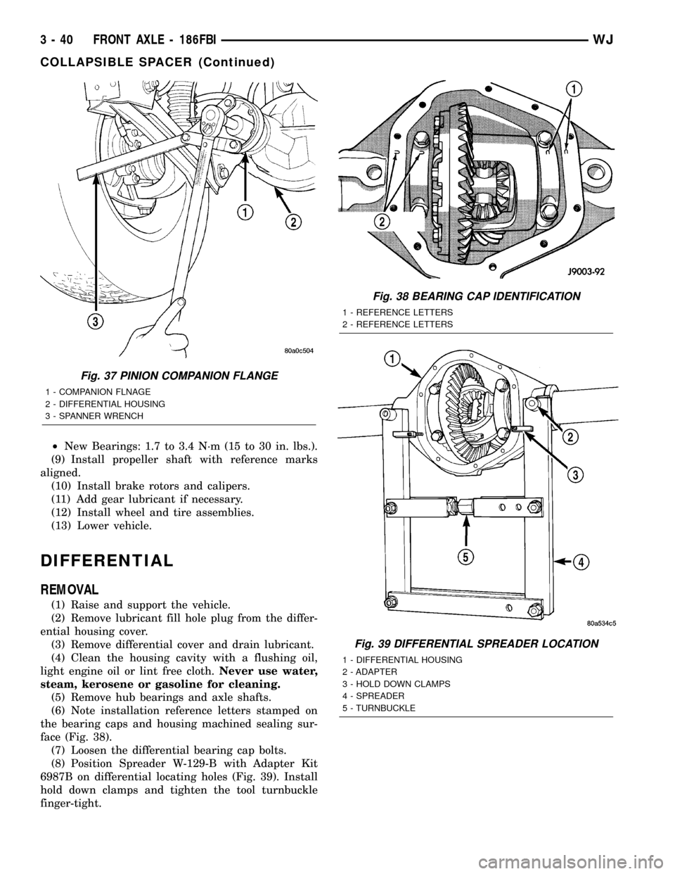
(6) Note installation reference letters stamped on
the bearing caps and housing machined sealing sur-
face (Fig. 38).
(7) Loosen the differential bearing cap bolts.
(8) Position Spreader W-129-B with Adapter Kit
6987B on differential locating holes (Fig. 39). Install
hold down clamps and tighten the tool turnbuckle
finger-tight.
Fig. 37 PINION COMPANION FLANGE
1 - COMPANION FLNAGE
2 - DIFFERENTIAL HOUSING
3 - SPANNER WRENCH
Fig. 38 BEARING CAP IDENTIFICATION
1 - REFERENCE LETTERS
2 - REFERENCE LETTERS
Fig. 39 DIFFERENTIAL SPREADER LOCATION
1 - DIFFERENTIAL HOUSING
2 - ADAPTER
3 - HOLD DOWN CLAMPS
4 - SPREADER
5 - TURNBUCKLE
3 - 40 FRONT AXLE - 186FBIWJ
COLLAPSIBLE SPACER (Continued)
Page 91 of 2199
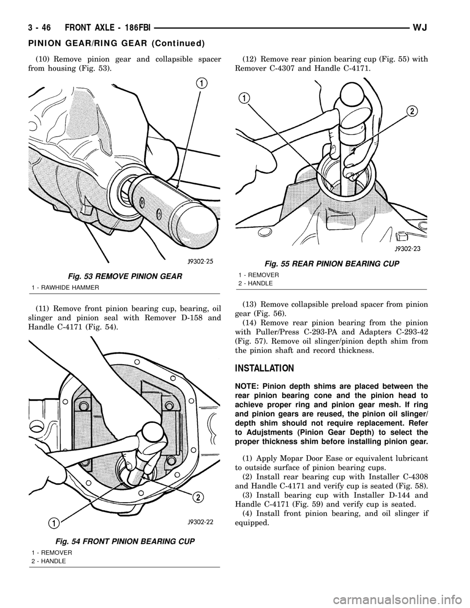
(10) Remove pinion gear and collapsible spacer
from housing (Fig. 53).
(11) Remove front pinion bearing cup, bearing, oil
slinger and pinion seal with Remover D-158 and
Handle C-4171 (Fig. 54).(12) Remove rear pinion bearing cup (Fig. 55) with
Remover C-4307 and Handle C-4171.
(13) Remove collapsible preload spacer from pinion
gear (Fig. 56).
(14) Remove rear pinion bearing from the pinion
with Puller/Press C-293-PA and Adapters C-293-42
(Fig. 57). Remove oil slinger/pinion depth shim from
the pinion shaft and record thickness.
INSTALLATION
NOTE: Pinion depth shims are placed between the
rear pinion bearing cone and the pinion head to
achieve proper ring and pinion gear mesh. If ring
and pinion gears are reused, the pinion oil slinger/
depth shim should not require replacement. Refer
to Adujstments (Pinion Gear Depth) to select the
proper thickness shim before installing pinion gear.
(1) Apply Mopar Door Ease or equivalent lubricant
to outside surface of pinion bearing cups.
(2) Install rear bearing cup with Installer C-4308
and Handle C-4171 and verify cup is seated (Fig. 58).
(3) Install bearing cup with Installer D-144 and
Handle C-4171 (Fig. 59) and verify cup is seated.
(4) Install front pinion bearing, and oil slinger if
equipped.
Fig. 53 REMOVE PINION GEAR
1 - RAWHIDE HAMMER
Fig. 54 FRONT PINION BEARING CUP
1 - REMOVER
2 - HANDLE
Fig. 55 REAR PINION BEARING CUP
1 - REMOVER
2 - HANDLE
3 - 46 FRONT AXLE - 186FBIWJ
PINION GEAR/RING GEAR (Continued)
Page 93 of 2199
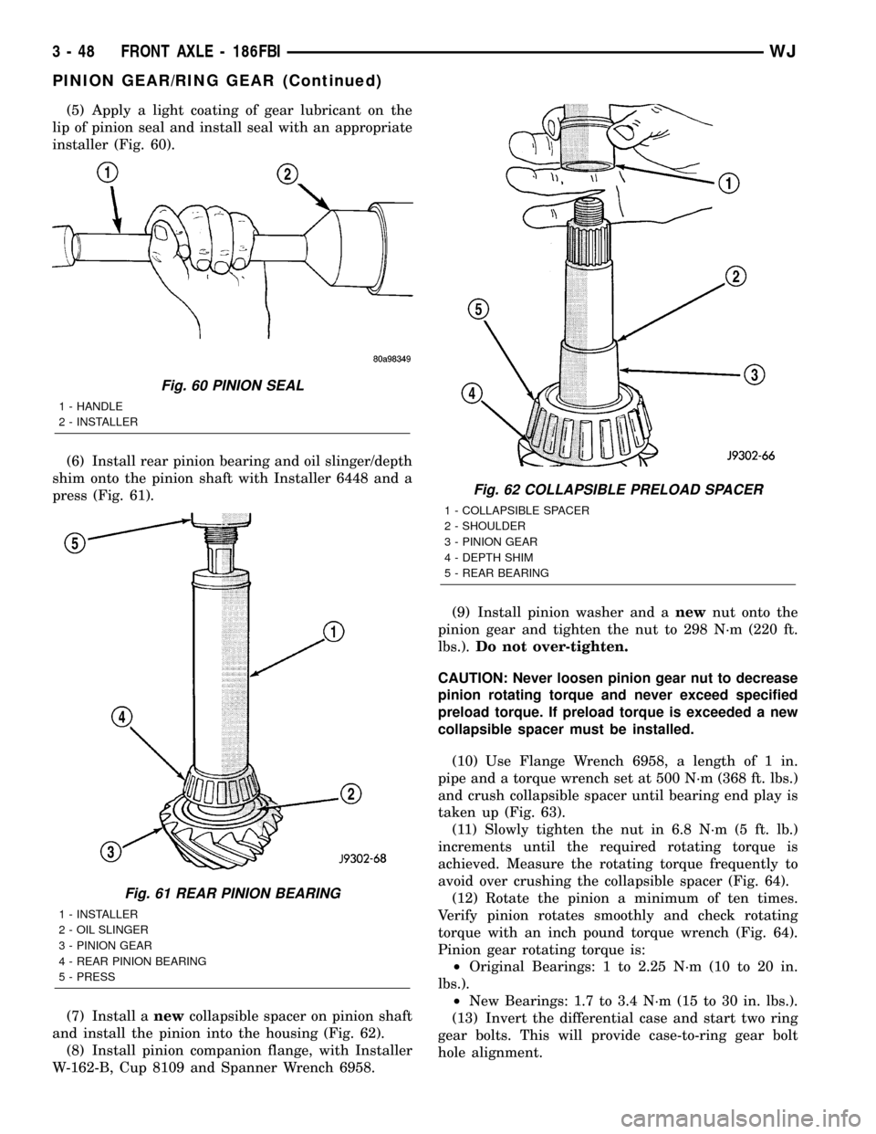
(5) Apply a light coating of gear lubricant on the
lip of pinion seal and install seal with an appropriate
installer (Fig. 60).
(6) Install rear pinion bearing and oil slinger/depth
shim onto the pinion shaft with Installer 6448 and a
press (Fig. 61).
(7) Install anewcollapsible spacer on pinion shaft
and install the pinion into the housing (Fig. 62).
(8) Install pinion companion flange, with Installer
W-162-B, Cup 8109 and Spanner Wrench 6958.(9) Install pinion washer and anewnut onto the
pinion gear and tighten the nut to 298 N´m (220 ft.
lbs.).Do not over-tighten.
CAUTION: Never loosen pinion gear nut to decrease
pinion rotating torque and never exceed specified
preload torque. If preload torque is exceeded a new
collapsible spacer must be installed.
(10) Use Flange Wrench 6958, a length of 1 in.
pipe and a torque wrench set at 500 N´m (368 ft. lbs.)
and crush collapsible spacer until bearing end play is
taken up (Fig. 63).
(11) Slowly tighten the nut in 6.8 N´m (5 ft. lb.)
increments until the required rotating torque is
achieved. Measure the rotating torque frequently to
avoid over crushing the collapsible spacer (Fig. 64).
(12) Rotate the pinion a minimum of ten times.
Verify pinion rotates smoothly and check rotating
torque with an inch pound torque wrench (Fig. 64).
Pinion gear rotating torque is:
²Original Bearings: 1 to 2.25 N´m (10 to 20 in.
lbs.).
²New Bearings: 1.7 to 3.4 N´m (15 to 30 in. lbs.).
(13) Invert the differential case and start two ring
gear bolts. This will provide case-to-ring gear bolt
hole alignment.
Fig. 60 PINION SEAL
1 - HANDLE
2 - INSTALLER
Fig. 61 REAR PINION BEARING
1 - INSTALLER
2 - OIL SLINGER
3 - PINION GEAR
4 - REAR PINION BEARING
5 - PRESS
Fig. 62 COLLAPSIBLE PRELOAD SPACER
1 - COLLAPSIBLE SPACER
2 - SHOULDER
3 - PINION GEAR
4 - DEPTH SHIM
5 - REAR BEARING
3 - 48 FRONT AXLE - 186FBIWJ
PINION GEAR/RING GEAR (Continued)
Page 120 of 2199
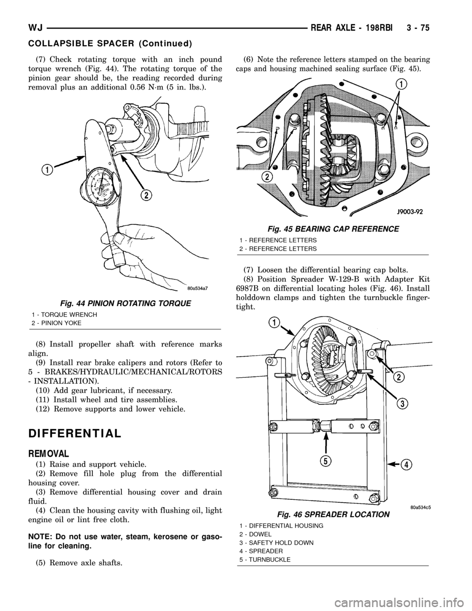
(7) Check rotating torque with an inch pound
torque wrench (Fig. 44). The rotating torque of the
pinion gear should be, the reading recorded during
removal plus an additional 0.56 N´m (5 in. lbs.).
(8) Install propeller shaft with reference marks
align.
(9) Install rear brake calipers and rotors (Refer to
5 - BRAKES/HYDRAULIC/MECHANICAL/ROTORS
- INSTALLATION).
(10) Add gear lubricant, if necessary.
(11) Install wheel and tire assemblies.
(12) Remove supports and lower vehicle.
DIFFERENTIAL
REMOVAL
(1) Raise and support vehicle.
(2) Remove fill hole plug from the differential
housing cover.
(3) Remove differential housing cover and drain
fluid.
(4) Clean the housing cavity with flushing oil, light
engine oil or lint free cloth.
NOTE: Do not use water, steam, kerosene or gaso-
line for cleaning.
(5) Remove axle shafts.(6)
Note the reference letters stamped on the bearing
caps and housing machined sealing surface (Fig. 45).
(7) Loosen the differential bearing cap bolts.
(8) Position Spreader W-129-B with Adapter Kit
6987B on differential locating holes (Fig. 46). Install
holddown clamps and tighten the turnbuckle finger-
tight.
Fig. 44 PINION ROTATING TORQUE
1 - TORQUE WRENCH
2 - PINION YOKE
Fig. 45 BEARING CAP REFERENCE
1 - REFERENCE LETTERS
2 - REFERENCE LETTERS
Fig. 46 SPREADER LOCATION
1 - DIFFERENTIAL HOUSING
2 - DOWEL
3 - SAFETY HOLD DOWN
4 - SPREADER
5 - TURNBUCKLE
WJREAR AXLE - 198RBI 3 - 75
COLLAPSIBLE SPACER (Continued)
Page 130 of 2199
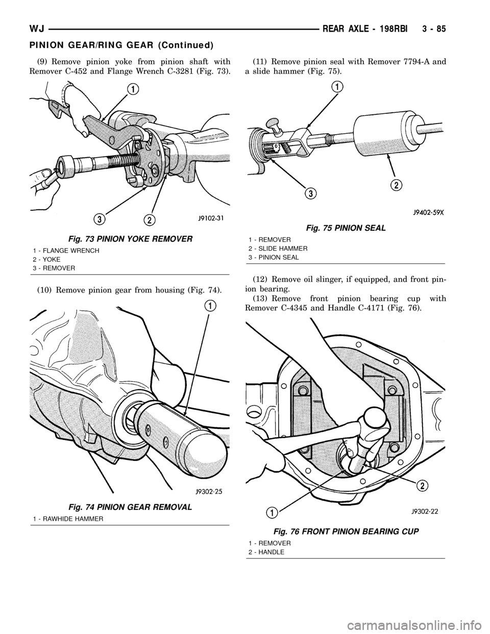
(9) Remove pinion yoke from pinion shaft with
Remover C-452 and Flange Wrench C-3281 (Fig. 73).
(10) Remove pinion gear from housing (Fig. 74).(11) Remove pinion seal with Remover 7794-A and
a slide hammer (Fig. 75).
(12) Remove oil slinger, if equipped, and front pin-
ion bearing.
(13) Remove front pinion bearing cup with
Remover C-4345 and Handle C-4171 (Fig. 76).
Fig. 73 PINION YOKE REMOVER
1 - FLANGE WRENCH
2 - YOKE
3 - REMOVER
Fig. 74 PINION GEAR REMOVAL
1 - RAWHIDE HAMMER
Fig. 75 PINION SEAL
1 - REMOVER
2 - SLIDE HAMMER
3 - PINION SEAL
Fig. 76 FRONT PINION BEARING CUP
1 - REMOVER
2 - HANDLE
WJREAR AXLE - 198RBI 3 - 85
PINION GEAR/RING GEAR (Continued)
Page 160 of 2199
NOTE: If more than 380 N´m (280 ft. lbs.) torque is
required to crush the collapsible spacer, the spacer
is defective and must be replaced.
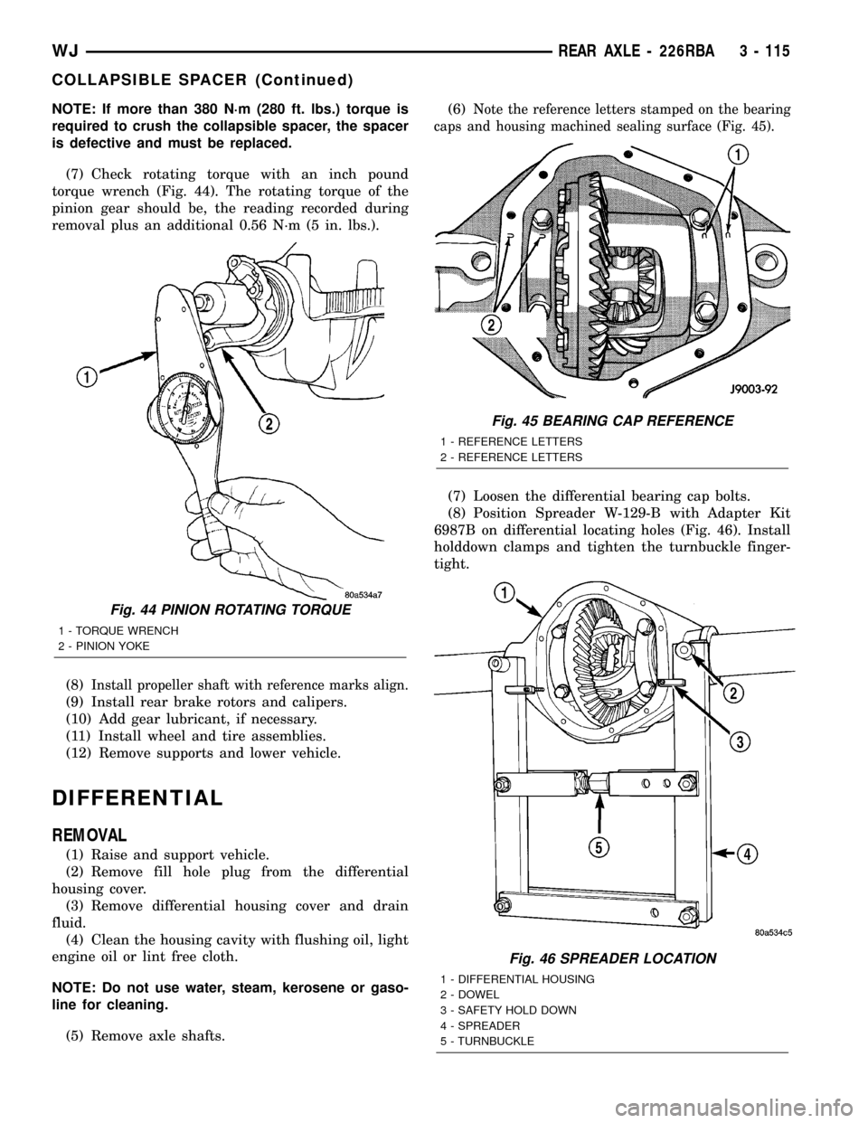
(7) Check rotating torque with an inch pound
torque wrench (Fig. 44). The rotating torque of the
pinion gear should be, the reading recorded during
removal plus an additional 0.56 N´m (5 in. lbs.).
(8)
Install propeller shaft with reference marks align.
(9) Install rear brake rotors and calipers.
(10) Add gear lubricant, if necessary.
(11) Install wheel and tire assemblies.
(12) Remove supports and lower vehicle.
DIFFERENTIAL
REMOVAL
(1) Raise and support vehicle.
(2) Remove fill hole plug from the differential
housing cover.
(3) Remove differential housing cover and drain
fluid.
(4) Clean the housing cavity with flushing oil, light
engine oil or lint free cloth.
NOTE: Do not use water, steam, kerosene or gaso-
line for cleaning.
(5) Remove axle shafts.(6)
Note the reference letters stamped on the bearing
caps and housing machined sealing surface (Fig. 45).
(7) Loosen the differential bearing cap bolts.
(8) Position Spreader W-129-B with Adapter Kit
6987B on differential locating holes (Fig. 46). Install
holddown clamps and tighten the turnbuckle finger-
tight.
Fig. 44 PINION ROTATING TORQUE
1 - TORQUE WRENCH
2 - PINION YOKE
Fig. 45 BEARING CAP REFERENCE
1 - REFERENCE LETTERS
2 - REFERENCE LETTERS
Fig. 46 SPREADER LOCATION
1 - DIFFERENTIAL HOUSING
2 - DOWEL
3 - SAFETY HOLD DOWN
4 - SPREADER
5 - TURNBUCKLE
WJREAR AXLE - 226RBA 3 - 115
COLLAPSIBLE SPACER (Continued)
Page 170 of 2199
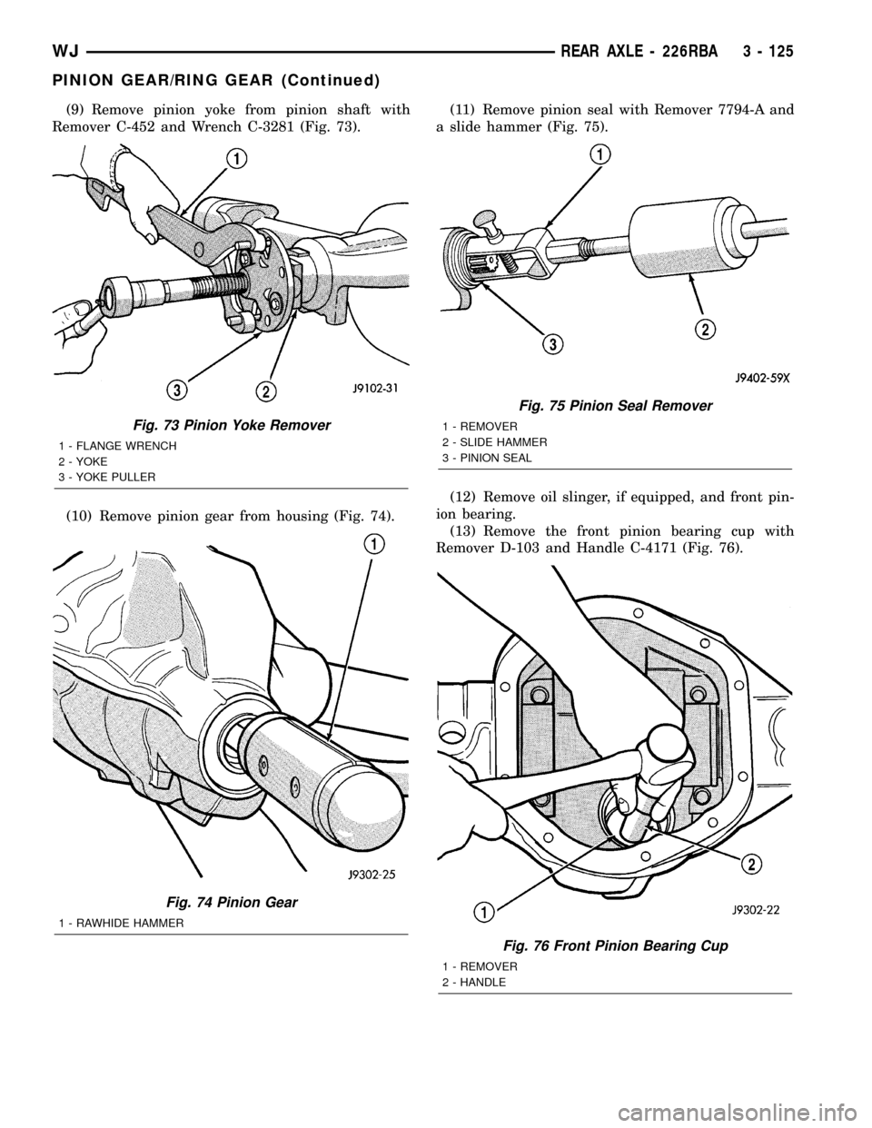
(9) Remove pinion yoke from pinion shaft with
Remover C-452 and Wrench C-3281 (Fig. 73).
(10) Remove pinion gear from housing (Fig. 74).(11) Remove pinion seal with Remover 7794-A and
a slide hammer (Fig. 75).
(12) Remove oil slinger, if equipped, and front pin-
ion bearing.
(13) Remove the front pinion bearing cup with
Remover D-103 and Handle C-4171 (Fig. 76).
Fig. 73 Pinion Yoke Remover
1 - FLANGE WRENCH
2 - YOKE
3 - YOKE PULLER
Fig. 74 Pinion Gear
1 - RAWHIDE HAMMER
Fig. 75 Pinion Seal Remover
1 - REMOVER
2 - SLIDE HAMMER
3 - PINION SEAL
Fig. 76 Front Pinion Bearing Cup
1 - REMOVER
2 - HANDLE
WJREAR AXLE - 226RBA 3 - 125
PINION GEAR/RING GEAR (Continued)
Page 1536 of 2199
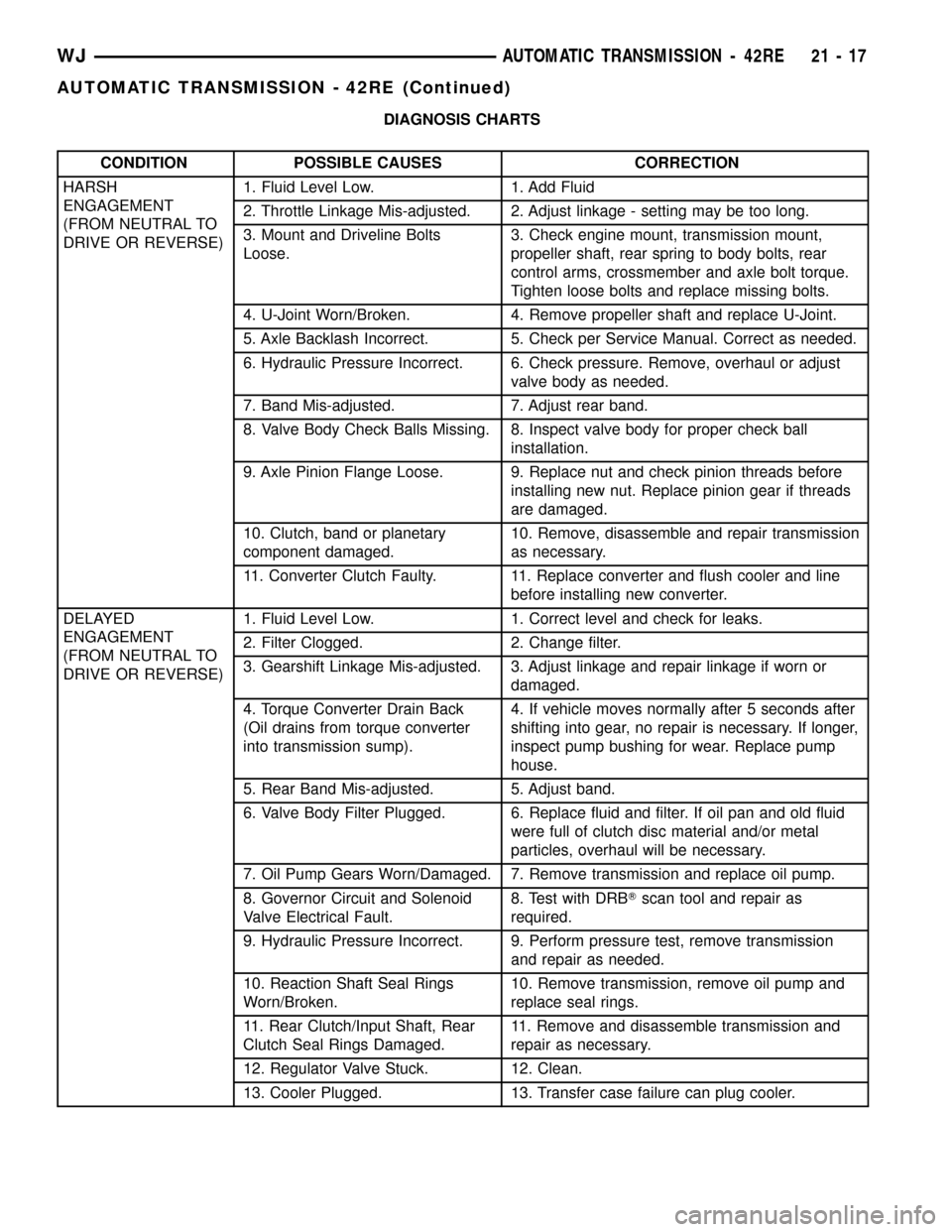
DIAGNOSIS CHARTS
CONDITION POSSIBLE CAUSES CORRECTION
HARSH
ENGAGEMENT
(FROM NEUTRAL TO
DRIVE OR REVERSE)1. Fluid Level Low. 1. Add Fluid
2. Throttle Linkage Mis-adjusted. 2. Adjust linkage - setting may be too long.
3. Mount and Driveline Bolts
Loose.3. Check engine mount, transmission mount,
propeller shaft, rear spring to body bolts, rear
control arms, crossmember and axle bolt torque.
Tighten loose bolts and replace missing bolts.
4. U-Joint Worn/Broken. 4. Remove propeller shaft and replace U-Joint.
5. Axle Backlash Incorrect. 5. Check per Service Manual. Correct as needed.
6. Hydraulic Pressure Incorrect. 6. Check pressure. Remove, overhaul or adjust
valve body as needed.
7. Band Mis-adjusted. 7. Adjust rear band.
8. Valve Body Check Balls Missing. 8. Inspect valve body for proper check ball
installation.
9. Axle Pinion Flange Loose. 9. Replace nut and check pinion threads before
installing new nut. Replace pinion gear if threads
are damaged.
10. Clutch, band or planetary
component damaged.10. Remove, disassemble and repair transmission
as necessary.
11. Converter Clutch Faulty. 11. Replace converter and flush cooler and line
before installing new converter.
DELAYED
ENGAGEMENT
(FROM NEUTRAL TO
DRIVE OR REVERSE)1. Fluid Level Low. 1. Correct level and check for leaks.
2. Filter Clogged. 2. Change filter.
3. Gearshift Linkage Mis-adjusted. 3. Adjust linkage and repair linkage if worn or
damaged.
4. Torque Converter Drain Back
(Oil drains from torque converter
into transmission sump).4. If vehicle moves normally after 5 seconds after
shifting into gear, no repair is necessary. If longer,
inspect pump bushing for wear. Replace pump
house.
5. Rear Band Mis-adjusted. 5. Adjust band.
6. Valve Body Filter Plugged. 6. Replace fluid and filter. If oil pan and old fluid
were full of clutch disc material and/or metal
particles, overhaul will be necessary.
7. Oil Pump Gears Worn/Damaged. 7. Remove transmission and replace oil pump.
8. Governor Circuit and Solenoid
Valve Electrical Fault.8. Test with DRBTscan tool and repair as
required.
9. Hydraulic Pressure Incorrect. 9. Perform pressure test, remove transmission
and repair as needed.
10. Reaction Shaft Seal Rings
Worn/Broken.10. Remove transmission, remove oil pump and
replace seal rings.
11. Rear Clutch/Input Shaft, Rear
Clutch Seal Rings Damaged.11. Remove and disassemble transmission and
repair as necessary.
12. Regulator Valve Stuck. 12. Clean.
13. Cooler Plugged. 13. Transfer case failure can plug cooler.
WJAUTOMATIC TRANSMISSION - 42RE 21 - 17
AUTOMATIC TRANSMISSION - 42RE (Continued)
Page 1588 of 2199
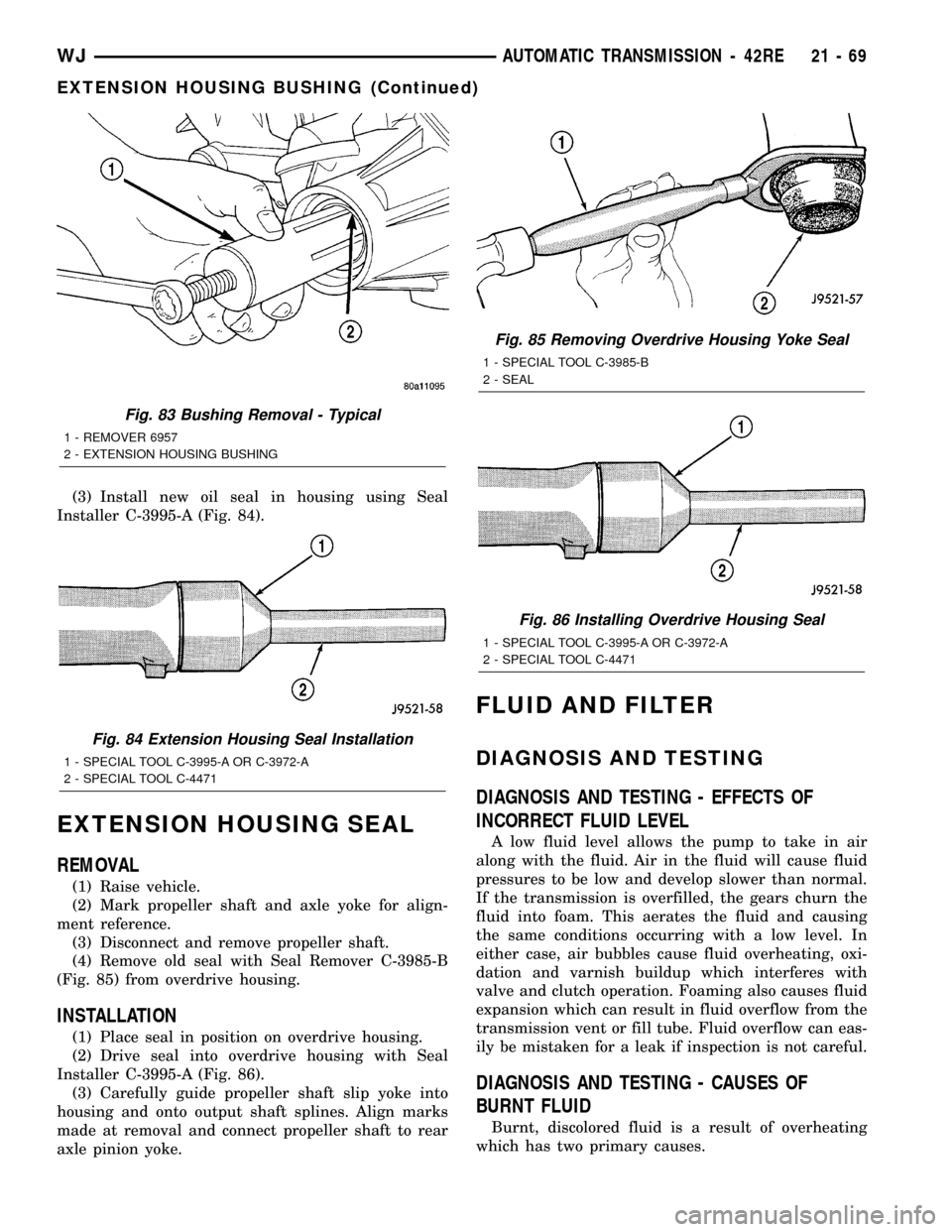
(3) Install new oil seal in housing using Seal
Installer C-3995-A (Fig. 84).
EXTENSION HOUSING SEAL
REMOVAL
(1) Raise vehicle.
(2) Mark propeller shaft and axle yoke for align-
ment reference.
(3) Disconnect and remove propeller shaft.
(4) Remove old seal with Seal Remover C-3985-B
(Fig. 85) from overdrive housing.
INSTALLATION
(1) Place seal in position on overdrive housing.
(2) Drive seal into overdrive housing with Seal
Installer C-3995-A (Fig. 86).
(3) Carefully guide propeller shaft slip yoke into
housing and onto output shaft splines. Align marks
made at removal and connect propeller shaft to rear
axle pinion yoke.
FLUID AND FILTER
DIAGNOSIS AND TESTING
DIAGNOSIS AND TESTING - EFFECTS OF
INCORRECT FLUID LEVEL
A low fluid level allows the pump to take in air
along with the fluid. Air in the fluid will cause fluid
pressures to be low and develop slower than normal.
If the transmission is overfilled, the gears churn the
fluid into foam. This aerates the fluid and causing
the same conditions occurring with a low level. In
either case, air bubbles cause fluid overheating, oxi-
dation and varnish buildup which interferes with
valve and clutch operation. Foaming also causes fluid
expansion which can result in fluid overflow from the
transmission vent or fill tube. Fluid overflow can eas-
ily be mistaken for a leak if inspection is not careful.
DIAGNOSIS AND TESTING - CAUSES OF
BURNT FLUID
Burnt, discolored fluid is a result of overheating
which has two primary causes.
Fig. 83 Bushing Removal - Typical
1 - REMOVER 6957
2 - EXTENSION HOUSING BUSHING
Fig. 84 Extension Housing Seal Installation
1 - SPECIAL TOOL C-3995-A OR C-3972-A
2 - SPECIAL TOOL C-4471
Fig. 85 Removing Overdrive Housing Yoke Seal
1 - SPECIAL TOOL C-3985-B
2 - SEAL
Fig. 86 Installing Overdrive Housing Seal
1 - SPECIAL TOOL C-3995-A OR C-3972-A
2 - SPECIAL TOOL C-4471
WJAUTOMATIC TRANSMISSION - 42RE 21 - 69
EXTENSION HOUSING BUSHING (Continued)
Page 1844 of 2199
INPUT AND LOW RANGE GEARS
Inspect the low range gear pinions and pinion pins.
Replace the low range gear if any of the pins or pin-
ions are worn or damaged.
Inspect the thrust washers, retainer, and snap-
ring. Replace the snap-ring if bent, or distorted.
Replace the thrust washers and retainer if worn,
cracked or damaged in any way.
Examine the input gear carefully. Be sure the gear
teeth and bearing surfaces are in good condition.
Replace the gear if wear or damage is evident.
Check the input gear pilot bearing. Rotate the
bearing and check for roughness or noise. Also check
bearing position in the bore. The bearing should be
recessed approximately 2.5 mm (0.100 in.) below the
top edge of the bore. The bearing should not be
seated at the bottom of the bore. Replace the bearing
if worn, or roughness is evident. Replace both the
gear and bearing if the bearing is a loose fit in the
bore.
GEAR CASE AND RETAINERS
Examine both case halves and retainers carefully.
Replace any retainer or case half if wear, cracks, or
other damage is evident.
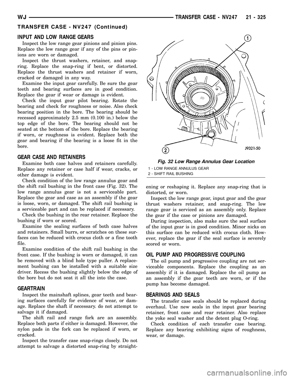
Check condition of the low range annulus gear and
the shift rail bushing in the front case (Fig. 32). The
low range annulus gear is not a serviceable part.
Replace the gear and case as an assembly if the gear
is loose, worn, or damaged. The shift rail bushing is
a serviceable part and can be replaced if necessary.
Check the bushing in the rear retainer. Replace the
bushing if worn or scored.
Examine the sealing surfaces of both case halves
and retainers. Small burrs, or scratches on these sur-
faces can be reduced with crocus cloth or a fine tooth
file.
Examine condition of the shift rail bushing in the
front case. If the bushing is worn or damaged, it can
be removed with a blind hole type puller. A replace-
ment bushing can be installed with a suitable size
driver. Recess the bushing slightly below the edge of
the bore but do not seat it all the into the case.
GEARTRAIN
Inspect the mainshaft splines, gear teeth and bear-
ing surfaces carefully for evidence of wear, or dam-
age. Replace the shaft if necessary. do not attempt to
salvage it if damaged.
The shift rail and range fork are an assembly.
Replace both parts if either is damaged. However, the
nylon pads in the fork can be replaced if worn, or
cracked.
Inspect the transfer case snap-rings closely. Do not
attempt to salvage a distorted snap-ring by straight-ening or reshaping it. Replace any snap-ring that is
distorted, or worn.
Inspect the low range gear, input gear and the gear
thrust washers retainer, and snap-ring. The low
range gear is serviced as an assembly only. Replace
the gear if the case or pinions are damaged.
During inspection, also make sure the seal surface
of the input gear is in good condition. Minor nicks on
this surface can be reduced with crocus cloth. How-
ever, replace the gear if the seal surface is severely
scored or worn.
OIL PUMP AND PROGRESSIVE COUPLING
The oil pump and progressive coupling are not ser-
viceable components. Replace the coupling as an
assembly if it is damaged. Replace the oil pump as
an assembly if the gear teeth are worn, or if the
pump has become damaged.
BEARINGS AND SEALS
The transfer case seals should be replaced during
overhaul. Use new seals in the input gear bearing
retainer, front case and rear retainer. Also replace
the yoke seal washer and the detent plug O-ring.
Check condition of each transfer case bearing.
Replace any bearing exhibiting signs of roughness,
wear, or damage.
Fig. 32 Low Range Annulus Gear Location
1 - LOW RANGE ANNULUS GEAR
2 - SHIFT RAIL BUSHING
WJTRANSFER CASE - NV247 21 - 325
TRANSFER CASE - NV247 (Continued)