transmission cooling li e JEEP GRAND CHEROKEE 2002 WJ / 2.G Workshop Manual
[x] Cancel search | Manufacturer: JEEP, Model Year: 2002, Model line: GRAND CHEROKEE, Model: JEEP GRAND CHEROKEE 2002 WJ / 2.GPages: 2199, PDF Size: 76.01 MB
Page 12 of 2199
LUBRICATION & MAINTENANCE
TABLE OF CONTENTS
page page
LUBRICATION & MAINTENANCE
SPECIFICATIONS - FLUID CAPACITIES.......1
INTERNATIONAL SYMBOLS
DESCRIPTION..........................2
PARTS & LUBRICANT RECOMMENDATION
STANDARD PROCEDURE - PARTS &
LUBRICANT RECOMMENDATIONS.........2
FLUID TYPES
DESCRIPTION
DESCRIPTION - ENGINE COOLANT........2
DESCRIPTION - ENGINE COOLANT........3
ENGINE OIL..........................4
DESCRIPTION - ENGINE OIL.............4
DESCRIPTION........................5
DESCRIPTION - TRANSFER CASE - NV242 . . 5
DESCRIPTION - TRANSFER CASE - NV247 . . 5
DESCRIPTION - AUTOMATIC
TRANSMISSION FLUID..................5
DESCRIPTION - ENGINE OIL - DIESEL
ENGINES............................6OPERATION - AUTOMATIC TRANSMISSION
FLUID...............................6
FLUID FILL/CHECK LOCATIONS
INSPECTION - FLUID FILL/CHECK
LOCATIONS..........................6
MAINTENANCE SCHEDULES
DESCRIPTION..........................6
LIFT POINTS
STANDARD PROCEDURE - HOISTING AND
JACKING RECOMMENDATIONS...........6
JUMP STARTING
STANDARD PROCEDURE - JUMP STARTING . . 7
EMERGENCY TOW HOOKS
DESCRIPTION..........................8
TOWING
STANDARD PROCEDURE - TOWING
RECOMMENDATIONS...................8
LUBRICATION &
MAINTENANCE
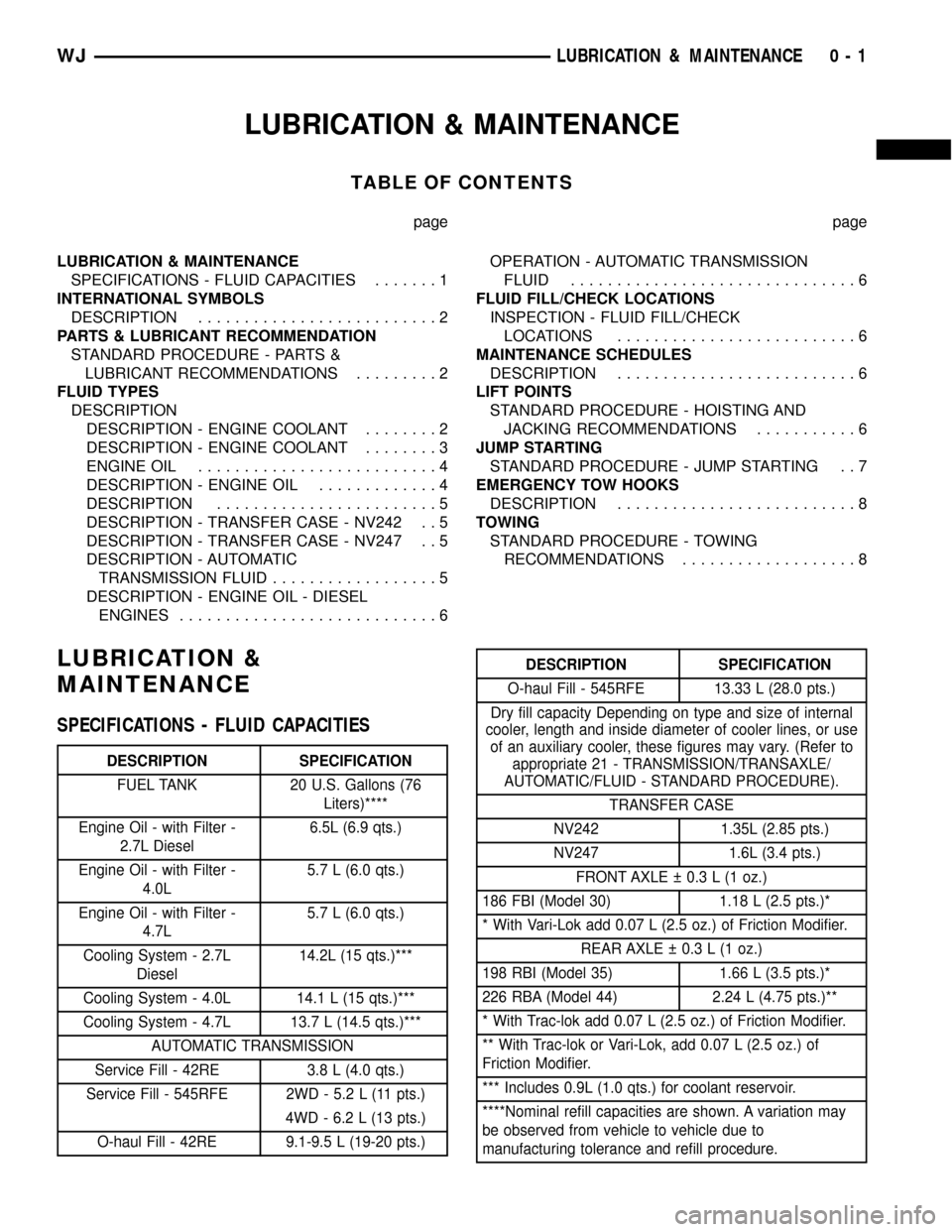
SPECIFICATIONS - FLUID CAPACITIES
DESCRIPTION SPECIFICATION
FUEL TANK 20 U.S. Gallons (76
Liters)****
Engine Oil - with Filter -
2.7L Diesel6.5L (6.9 qts.)
Engine Oil - with Filter -
4.0L5.7 L (6.0 qts.)
Engine Oil - with Filter -
4.7L5.7 L (6.0 qts.)
Cooling System - 2.7L
Diesel14.2L (15 qts.)***
Cooling System - 4.0L 14.1 L (15 qts.)***
Cooling System - 4.7L 13.7 L (14.5 qts.)***
AUTOMATIC TRANSMISSION
Service Fill - 42RE 3.8 L (4.0 qts.)
Service Fill - 545RFE 2WD - 5.2 L (11 pts.)
4WD - 6.2 L (13 pts.)
O-haul Fill - 42RE 9.1-9.5 L (19-20 pts.)
DESCRIPTION SPECIFICATION
O-haul Fill - 545RFE 13.33 L (28.0 pts.)
Dry fill capacity Depending on type and size of internal
cooler, length and inside diameter of cooler lines, or use
of an auxiliary cooler, these figures may vary. (Refer to
appropriate 21 - TRANSMISSION/TRANSAXLE/
AUTOMATIC/FLUID - STANDARD PROCEDURE).
TRANSFER CASE
NV242 1.35L (2.85 pts.)
NV247 1.6L (3.4 pts.)
FRONT AXLE 0.3 L (1 oz.)
186 FBI (Model 30) 1.18 L (2.5 pts.)*
* With Vari-Lok add 0.07 L (2.5 oz.) of Friction Modifier.
REAR AXLE 0.3 L (1 oz.)
198 RBI (Model 35) 1.66 L (3.5 pts.)*
226 RBA (Model 44) 2.24 L (4.75 pts.)**
* With Trac-lok add 0.07 L (2.5 oz.) of Friction Modifier.
** With Trac-lok or Vari-Lok, add 0.07 L (2.5 oz.) of
Friction Modifier.
*** Includes 0.9L (1.0 qts.) for coolant reservoir.
****Nominal refill capacities are shown. A variation may
be observed from vehicle to vehicle due to
manufacturing tolerance and refill procedure.
WJLUBRICATION & MAINTENANCE 0 - 1
Page 224 of 2199
COOLING
TABLE OF CONTENTS
page page
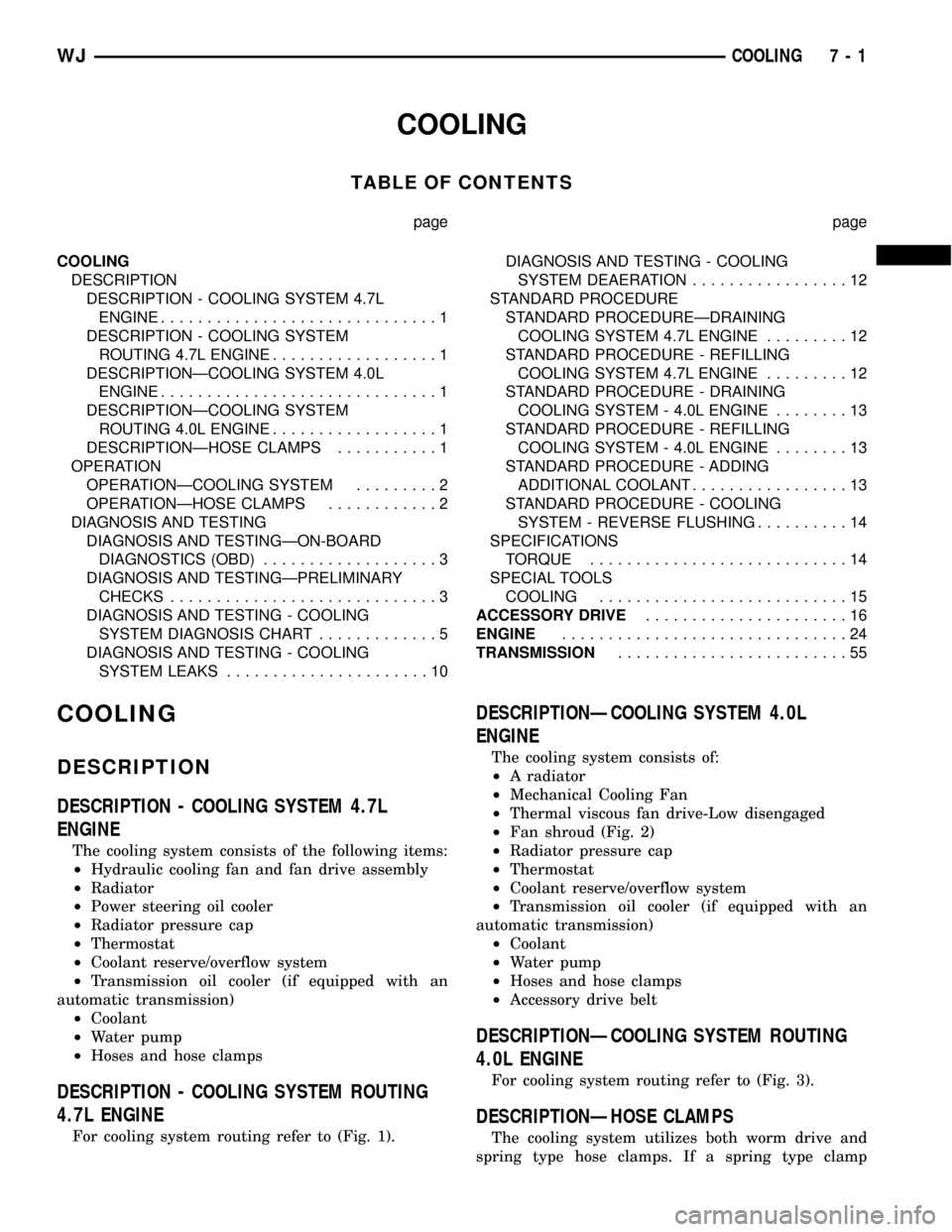
COOLING
DESCRIPTION
DESCRIPTION - COOLING SYSTEM 4.7L
ENGINE..............................1
DESCRIPTION - COOLING SYSTEM
ROUTING 4.7L ENGINE..................1
DESCRIPTIONÐCOOLING SYSTEM 4.0L
ENGINE..............................1
DESCRIPTIONÐCOOLING SYSTEM
ROUTING 4.0L ENGINE..................1
DESCRIPTIONÐHOSE CLAMPS...........1
OPERATION
OPERATIONÐCOOLING SYSTEM.........2
OPERATIONÐHOSE CLAMPS............2
DIAGNOSIS AND TESTING
DIAGNOSIS AND TESTINGÐON-BOARD
DIAGNOSTICS (OBD)...................3
DIAGNOSIS AND TESTINGÐPRELIMINARY
CHECKS.............................3
DIAGNOSIS AND TESTING - COOLING
SYSTEM DIAGNOSIS CHART.............5
DIAGNOSIS AND TESTING - COOLING
SYSTEM LEAKS......................10DIAGNOSIS AND TESTING - COOLING
SYSTEM DEAERATION.................12
STANDARD PROCEDURE
STANDARD PROCEDUREÐDRAINING
COOLING SYSTEM 4.7L ENGINE.........12
STANDARD PROCEDURE - REFILLING
COOLING SYSTEM 4.7L ENGINE.........12
STANDARD PROCEDURE - DRAINING
COOLING SYSTEM - 4.0L ENGINE........13
STANDARD PROCEDURE - REFILLING
COOLING SYSTEM - 4.0L ENGINE........13
STANDARD PROCEDURE - ADDING
ADDITIONAL COOLANT.................13
STANDARD PROCEDURE - COOLING
SYSTEM - REVERSE FLUSHING..........14
SPECIFICATIONS
TORQUE............................14
SPECIAL TOOLS
COOLING...........................15
ACCESSORY DRIVE......................16
ENGINE...............................24
TRANSMISSION.........................55
COOLING
DESCRIPTION
DESCRIPTION - COOLING SYSTEM 4.7L
ENGINE
The cooling system consists of the following items:
²Hydraulic cooling fan and fan drive assembly
²Radiator
²Power steering oil cooler
²Radiator pressure cap
²Thermostat
²Coolant reserve/overflow system
²Transmission oil cooler (if equipped with an
automatic transmission)
²Coolant
²Water pump
²Hoses and hose clamps
DESCRIPTION - COOLING SYSTEM ROUTING
4.7L ENGINE
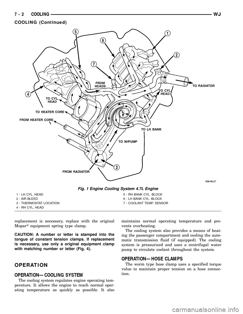
For cooling system routing refer to (Fig. 1).
DESCRIPTIONÐCOOLING SYSTEM 4.0L
ENGINE
The cooling system consists of:
²A radiator
²Mechanical Cooling Fan
²Thermal viscous fan drive-Low disengaged
²Fan shroud (Fig. 2)
²Radiator pressure cap
²Thermostat
²Coolant reserve/overflow system
²Transmission oil cooler (if equipped with an
automatic transmission)
²Coolant
²Water pump
²Hoses and hose clamps
²Accessory drive belt
DESCRIPTIONÐCOOLING SYSTEM ROUTING
4.0L ENGINE
For cooling system routing refer to (Fig. 3).
DESCRIPTIONÐHOSE CLAMPS
The cooling system utilizes both worm drive and
spring type hose clamps. If a spring type clamp
WJCOOLING 7 - 1
Page 225 of 2199
replacement is necessary, replace with the original
Mopartequipment spring type clamp.
CAUTION: A number or letter is stamped into the
tongue of constant tension clamps. If replacement
is necessary, use only a original equipment clamp
with matching number or letter (Fig. 4).
OPERATION
OPERATIONÐCOOLING SYSTEM
The cooling system regulates engine operating tem-
perature. It allows the engine to reach normal oper-
ating temperature as quickly as possible. It alsomaintains normal operating temperature and pre-
vents overheating.
The cooling system also provides a means of heat-
ing the passenger compartment and cooling the auto-
matic transmission fluid (if equipped). The cooling
system is pressurized and uses a centrifugal water
pump to circulate coolant throughout the system.
OPERATIONÐHOSE CLAMPS
The worm type hose clamp uses a specified torque
value to maintain proper tension on a hose connec-
tion.
Fig. 1 Engine Cooling System 4.7L Engine
1 - LH CYL. HEAD
2 - AIR BLEED
3 - THERMOSTAT LOCATION
4 - RH CYL. HEAD5 - RH BANK CYL. BLOCK
6 - LH BANK CYL. BLOCK
7 - COOLANT TEMP. SENSOR
7 - 2 COOLINGWJ
COOLING (Continued)
Page 233 of 2199
CONDITION POSSIBLE CAUSES CORRECTION
COOLANT LEVEL
CHANGES IN COOLANT
RESERVE/OVERFLOW
TANK. TEMPERATURE
GAUGE IS IN NORMAL
RANGE1. Level changes are to be expected
as coolant volume fluctuates with
engine temperature. If the level in
the tank was between the FULL and
ADD marks at normal operating
temperature, the level should return
to within that range after operation
at elevated temperatures.1. A normal condition. No repair is necessary.
FAN RUNS ALL THE
TIME1. Fan control sensors inoperative. 1. Check for DTC's. Verify sensor readings.
2. Fan control solenoid stuck9on9. 2. Check fan operation speeds. Refer to fan
speed operation table.
3. Fan control solenoid harness
damaged.3. Check for DTC 1499. Repair as required.
4. Transmission temperature too
high.4. Check for transmission over temp. DTC.
5. Engine coolant temperature too
high.5. (a) Check coolant level. Correct level as
required.
(b) Thermostat stuck. Replace thermostat.
(c) Water pump failed. Replace water pump.
(d) Coolant flow restricted. Clean radiator.
(e) Air flow over radiator obstructed.Remove
obstruction.
DIAGNOSIS AND TESTING - COOLING SYSTEM
LEAKS
ULTRAVIOLET LIGHT METHOD
A leak detection additive is available through the
parts department that can be added to cooling sys-
tem. The additive is highly visible under ultraviolet
light (black light). Pour one ounce of additive into
cooling system. Place heater control unit in HEAT
position. Start and operate engine until radiator
upper hose is warm to touch. Aim the commercially
available black light tool at components to be
checked. If leaks are present, black light will cause
additive to glow a bright green color.
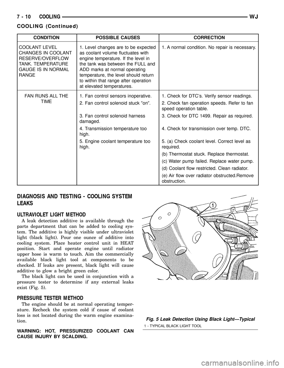
The black light can be used in conjunction with a
pressure tester to determine if any external leaks
exist (Fig. 5).
PRESSURE TESTER METHOD
The engine should be at normal operating temper-
ature. Recheck the system cold if cause of coolant
loss is not located during the warm engine examina-
tion.
WARNING: HOT, PRESSURIZED COOLANT CAN
CAUSE INJURY BY SCALDING.
Fig. 5 Leak Detection Using Black LightÐTypical
1 - TYPICAL BLACK LIGHT TOOL
7 - 10 COOLINGWJ
COOLING (Continued)
Page 234 of 2199
Carefully remove radiator pressure cap from filler
neck and check coolant level. Push down on cap to
disengage it from stop tabs. Wipe inside of filler neck
and examine lower inside sealing seat for nicks,
cracks, paint, dirt and solder residue. Inspect radia-
tor-to- reserve/overflow tank hose for internal
obstructions. Insert a wire through the hose to be
sure it is not obstructed.
Inspect cams on outside of filler neck. If cams are
damaged, seating of pressure cap valve and tester
seal will be affected.
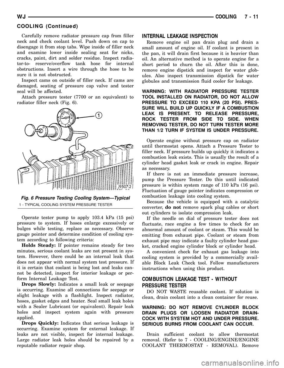
Attach pressure tester (7700 or an equivalent) to
radiator filler neck (Fig. 6).
Operate tester pump to apply 103.4 kPa (15 psi)
pressure to system. If hoses enlarge excessively or
bulges while testing, replace as necessary. Observe
gauge pointer and determine condition of cooling sys-
tem according to following criteria:
Holds Steady:If pointer remains steady for two
minutes, serious coolant leaks are not present in sys-
tem. However, there could be an internal leak that
does not appear with normal system test pressure. If
it is certain that coolant is being lost and leaks can-
not be detected, inspect for interior leakage or per-
form Internal Leakage Test.
Drops Slowly:Indicates a small leak or seepage
is occurring. Examine all connections for seepage or
slight leakage with a flashlight. Inspect radiator,
hoses, gasket edges and heater. Seal small leak holes
with a Sealer Lubricant (or equivalent). Repair leak
holes and inspect system again with pressure
applied.
Drops Quickly:Indicates that serious leakage is
occurring. Examine system for external leakage. If
leaks are not visible, inspect for internal leakage.
Large radiator leak holes should be repaired by a
reputable radiator repair shop.INTERNAL LEAKAGE INSPECTION
Remove engine oil pan drain plug and drain a
small amount of engine oil. If coolant is present in
the pan, it will drain first because it is heavier than
oil. An alternative method is to operate engine for a
short period to churn the oil. After this is done,
remove engine dipstick and inspect for water glob-
ules. Also inspect transmission dipstick for water
globules and transmission fluid cooler for leakage.
WARNING: WITH RADIATOR PRESSURE TESTER
TOOL INSTALLED ON RADIATOR, DO NOT ALLOW
PRESSURE TO EXCEED 110 KPA (20 PSI). PRES-
SURE WILL BUILD UP QUICKLY IF A COMBUSTION
LEAK IS PRESENT. TO RELEASE PRESSURE,
ROCK TESTER FROM SIDE TO SIDE. WHEN
REMOVING TESTER, DO NOT TURN TESTER MORE
THAN 1/2 TURN IF SYSTEM IS UNDER PRESSURE.
Operate engine without pressure cap on radiator
until thermostat opens. Attach a Pressure Tester to
filler neck. If pressure builds up quickly it indicates a
combustion leak exists. This is usually the result of a
cylinder head gasket leak or crack in engine. Repair
as necessary.
If there is not an immediate pressure increase,
pump the Pressure Tester. Do this until indicated
pressure is within system range of 110 kPa (16 psi).
Fluctuation of gauge pointer indicates compression or
combustion leakage into cooling system.
Because the vehicle is equipped with a catalytic
converter,do notremove spark plug cables or short
out cylinders to isolate compression leak.
If the needle on dial of pressure tester does not
fluctuate, race engine a few times to check for an
abnormal amount of coolant or steam. This would be
emitting from exhaust pipe. Coolant or steam from
exhaust pipe may indicate a faulty cylinder head gas-
ket, cracked engine cylinder block or cylinder head.
A convenient check for exhaust gas leakage into
cooling system is provided by a commercially avail-
able Block Leak Check tool. Follow manufacturers
instructions when using this product.
COMBUSTION LEAKAGE TEST - WITHOUT
PRESSURE TESTER
DO NOT WASTE reusable coolant. If solution is
clean, drain coolant into a clean container for reuse.
WARNING: DO NOT REMOVE CYLINDER BLOCK
DRAIN PLUGS OR LOOSEN RADIATOR DRAIN-
COCK WITH SYSTEM HOT AND UNDER PRESSURE.
SERIOUS BURNS FROM COOLANT CAN OCCUR.
Drain sufficient coolant to allow thermostat
removal. (Refer to 7 - COOLING/ENGINE/ENGINE
COOLANT THERMOSTAT - REMOVAL). Remove
Fig. 6 Pressure Testing Cooling SystemÐTypical
1 - TYPICAL COOLING SYSTEM PRESSURE TESTER
WJCOOLING 7 - 11
COOLING (Continued)
Page 251 of 2199
²Fan control valve
²Two stage G-rotor hydraulic drive
The hydraulic fan and drive is not serviceable.
Therefore any failure of the fan blade, hydraulic fan
drive or fan shroud requires replacement of the fan
module because the fan blade and hydraulic fan drive
are matched and balanced as a system and servicing
either separately would disrupt this balance.
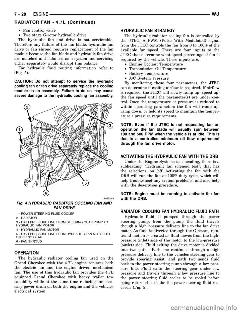
For hydraulic fluid routing information refer to
(Fig. 5).
CAUTION: Do not attempt to service the hydraulic
cooling fan or fan drive separately replace the cooling
module as an assembly. Failure to do so may cause
severe damage to the hydraulic cooling fan assembly.
OPERATION
The hydraulic radiator cooling fan used on the
Grand Cherokee with the 4.7L engine replaces both
the electric fan and the engine driven mechanical
fan. The use of this hydraulic fan provides the 4.7L
equipped Grand Cherokee with heavy trailer tow
capability while at the same time reducing unneces-
sary power drain on both the engine and the vehicles
electrical system.
HYDRAULIC FAN STRATEGY
The hydraulic radiator cooling fan is controlled by
the JTEC. A PWM (Pulse With Modulated) signal
from the JTEC controls the fan from 0 to 100% of the
available fan speed. There are four inputs to the
JTEC that determine what speed percentage of fan is
required by the vehicle. These inputs are:
²Engine Coolant Temperature
²Transmission Oil Temperature
²Battery Temperature
²A/C System Pressure
By monitoring these four parameters, the JTEC
can determine if cooling airflow is required. If airflow
is required, the JTEC will slowly ramp up (speed up)
the fan speed until the parameter(s) are under con-
trol. Once the temperature or pressure is reduced to
within operating parameters the fan will ramp up,
ramp down, or hold its speed to maintain the temper-
ature / pressure requirements.
NOTE: Even if the JTEC is not requesting fan on
operation the fan blade will usually spin between
100 and 500 RPM when the vehicle is at idle. This is
due to a controlled minimum oil flow requirement
through the fan drive motor.
ACTIVATING THE HYDRAULIC FAN WITH THE DRB
Under the Engine Systems test heading, there is a
subheading. ªHydraulic fan solenoid testº, that has
the selections, on /off. Activating the fan with the
DRB will run the fan at 100% duty cycle, which will
help troubleshoot any system problems, and also help
with the deaeration procedure.
NOTE: Engine must be running to activate the fan
with the DRB.
RADIATOR COOLING FAN HYDRAULIC FLUID PATH
Hydraulic fluid is pumped through the power
steering pump, from the pump the fluid travels
though a high pressure delivery line to the fan drive
motor. As fluid is diverted through the G-rotors, rota-
tional motion is created as fluid moves from the high-
pressure (inlet) side of the motor to the low-pressure
(outlet) side. Fluid exiting the drive motor is divided
into two paths. Path one continues through a high
pressure delivery line to the vehicles steering gear to
provide steering assist. and path two sends fluid
back to the power steering pump through a low pres-
sure line. Fluid exits the steering gear under low
pressure and travels through a low pressure line to
the power steering fluid cooler to be cooled before
being returned back the the power steering fluid res-
ervoir (Fig. 5).
Fig. 4 HYDRAULIC RADIATOR COOLING FAN AND
FAN DRIVE
1 - POWER STEERING FLUID COOLER
2 - RADIATOR
3 - HIGH PRESSURE LINE FROM STEERING GEAR PUMP TO
HYDRAULIC FAN MOTOR
4 - HYDRAULIC FAN MOTOR
5 - HIGH PRESSURE LINE FROM HYDRAULIC FAN MOTOR TO
STEERING GEAR
6 - FAN SHROUD
7 - 28 ENGINEWJ
RADIATOR FAN - 4.7L (Continued)
Page 264 of 2199
(6) Start the engine and operate at 2400 rpm.
Within ten minutes the air temperature (indicated on
the dial thermometer) should be up to 93É C (200É F).
Fan driveengagementshould have started to occur
at between 91É to 96É C (195É to 205É F). Engage-
ment is distinguishable by a definiteincreasein fan
flow noise (roaring). The timing light also will indi-
cate an increase in the speed of the fan.
(7) When the air temperature reaches 93É C (200É
F), remove the plastic sheet. Fan drivedisengage-
mentshould have started to occur at between 62É to
85É C (145É to 185É F). A definitedecreaseof fan
flow noise (roaring) should be noticed. If not, replace
the defective viscous fan drive unit.
PWM FAN CONTROL MODULE -
4.0L
DESCRIPTION
The pulse width modulated (PWM) radiator cooling
fan relay is located behind the front bumper fascia
below the right headlamp.
OPERATION
The PWM relay is used to control the speed of the
electric radiator cooling fan. It allows for multiple fan
speeds. This allows for improved fan noise and A/C
performance, better engine cooling, and additional
vehicle power.
PWM relay operation is controlled by the Power-
train Control Module (PCM). To operate the PWM
relay, the PCM looks at inputs from:
²Engine coolant temperature
²Ambient temperature from the body controller
²Vehicle speed
²Transmission oil temperature
²A/C switch position (A/C request)
REMOVAL
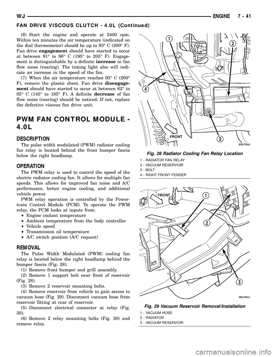
The Pulse Width Modulated (PWM) cooling fan
relay is located below the right headlamp behind the
bumper fascia (Fig. 28).
(1) Remove front bumper and grill assembly.
(2) Remove 1 support bolt near front of reservoir
(Fig. 28).
(3) Remove 2 reservoir mounting bolts.
(4) Remove reservoir from vehicle to gain access to
vacuum hose (Fig. 29). Disconnect vacuum hose from
reservoir fitting at rear of reservoir.
(5) Disconnect electrical connector at relay (Fig.
30).
(6) Remove 2 relay mounting bolts (Fig. 30) and
remove relay.
Fig. 28 Radiator Cooling Fan Relay Location
1 - RADIATOR FAN RELAY
2 - VACUUM RESERVOIR
3 - BOLT
4 - RIGHT FRONT FENDER
Fig. 29 Vacuum Reservoir Removal/Installation
1 - VACUUM HOSE
2 - RADIATOR
3 - VACUUM RESERVOIR
WJENGINE 7 - 41
FAN DRIVE VISCOUS CLUTCH - 4.0L (Continued)
Page 266 of 2199
(4) Remove two radiator mounting bolts.
(5) Disconnect both transmission cooler lines from
radiator.
(6) Disconnect electrical connector for the fan con-
trol solenoid.
(7) Disconnect the power steering cooler line from
cooler and filter.
(8) Disconnect the radiator upper and lower hoses.
(9) Disconnect the overflow hose from radiator.
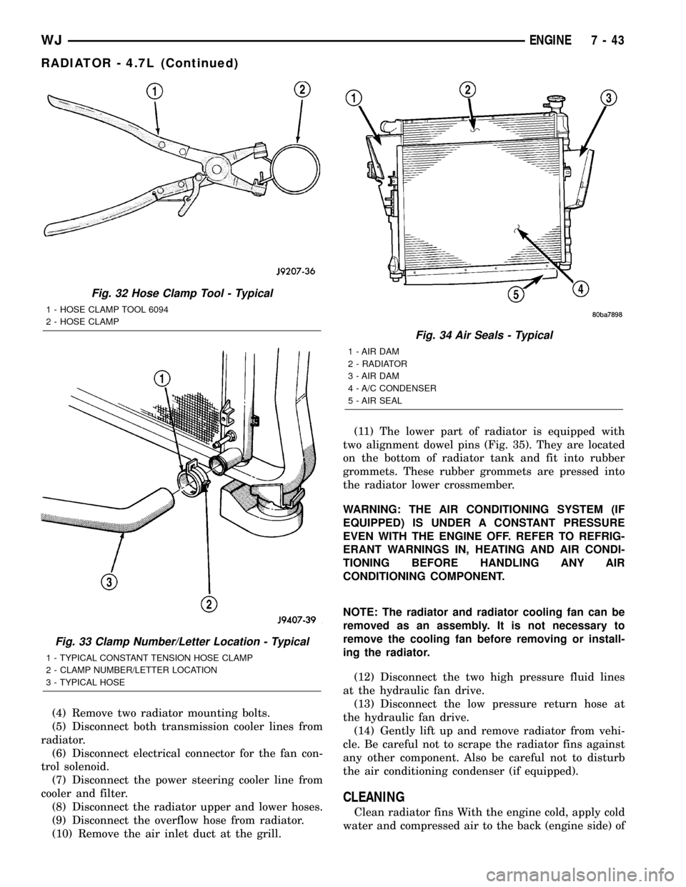
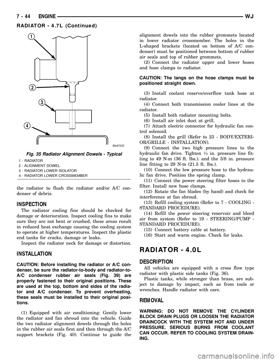
(10) Remove the air inlet duct at the grill.(11) The lower part of radiator is equipped with
two alignment dowel pins (Fig. 35). They are located
on the bottom of radiator tank and fit into rubber
grommets. These rubber grommets are pressed into
the radiator lower crossmember.
WARNING: THE AIR CONDITIONING SYSTEM (IF
EQUIPPED) IS UNDER A CONSTANT PRESSURE
EVEN WITH THE ENGINE OFF. REFER TO REFRIG-
ERANT WARNINGS IN, HEATING AND AIR CONDI-
TIONING BEFORE HANDLING ANY AIR
CONDITIONING COMPONENT.
NOTE: The radiator and radiator cooling fan can be
removed as an assembly. It is not necessary to
remove the cooling fan before removing or install-
ing the radiator.
(12) Disconnect the two high pressure fluid lines
at the hydraulic fan drive.
(13) Disconnect the low pressure return hose at
the hydraulic fan drive.
(14) Gently lift up and remove radiator from vehi-
cle. Be careful not to scrape the radiator fins against
any other component. Also be careful not to disturb
the air conditioning condenser (if equipped).
CLEANING
Clean radiator fins With the engine cold, apply cold
water and compressed air to the back (engine side) of
Fig. 32 Hose Clamp Tool - Typical
1 - HOSE CLAMP TOOL 6094
2 - HOSE CLAMP
Fig. 33 Clamp Number/Letter Location - Typical
1 - TYPICAL CONSTANT TENSION HOSE CLAMP
2 - CLAMP NUMBER/LETTER LOCATION
3 - TYPICAL HOSE
Fig. 34 Air Seals - Typical
1 - AIR DAM
2 - RADIATOR
3 - AIR DAM
4 - A/C CONDENSER
5 - AIR SEAL
WJENGINE 7 - 43
RADIATOR - 4.7L (Continued)
Page 267 of 2199
the radiator to flush the radiator and/or A/C con-
denser of debris.
INSPECTION
The radiator cooling fins should be checked for
damage or deterioration. Inspect cooling fins to make
sure they are not bent or crushed, these areas result
in reduced heat exchange causing the cooling system
to operate at higher temperatures. Inspect the plastic
end tanks for cracks, damage or leaks.
Inspect the radiator neck for damage or distortion.
INSTALLATION
CAUTION: Before installing the radiator or A/C con-
denser, be sure the radiator-to-body and radiator-to-
A/C condenser rubber air seals (Fig. 39) are
properly fastened to their original positions. These
are used at the top, bottom and sides of the radia-
tor and A/C condenser. To prevent overheating,
these seals must be installed to their original posi-
tions.
(1) Equipped with air conditioning: Gently lower
the radiator and fan shroud into the vehicle. Guide
the two radiator alignment dowels through the holes
in the rubber air seals first and then through the A/C
support brackets (Fig. 40). Continue to guide thealignment dowels into the rubber grommets located
in lower radiator crossmember. The holes in the
L-shaped brackets (located on bottom of A/C con-
denser) must be positioned between bottom of rubber
air seals and top of rubber grommets.
(2) Connect the radiator upper and lower hoses
and hose clamps to radiator.
CAUTION: The tangs on the hose clamps must be
positioned straight down.
(3) Install coolant reserve/overflow tank hose at
radiator.
(4) Connect both transmission cooler lines at the
radiator.
(5) Install both radiator mounting bolts.
(6) Install air inlet duct at grill.
(7) Attach electric connector for hydraulic fan con-
trol solenoid.
(8) Install the grill (Refer to 23 - BODY/EXTERI-
OR/GRILLE - INSTALLATION).
(9) Connect the two high pressure lines to the
hydraulic fan drive. Tighten
1¤2in. pressure line fit-
ting to 49 N´m (36 ft. lbs.). and the 3/8 in. pressure
line fitting to 29 N´m (21.5 ft. lbs.).
(10) Connect the low pressure hose to the hydrau-
lic fan drive. Position the spring clamp.
(11) Connect the power steering filter hoses to the
filter. Install new hose clamps.
(12) Rotate the fan blades (by hand) and check for
interference at fan shroud.
(13) Refill cooling system (Refer to 7 - COOLING -
STANDARD PROCEDURE).
(14) Refill the power steering reservoir and bleed
air from system (Refer to 19 - STEERING/PUMP -
STANDARD PROCEDURE).
(15) Connect battery cable at battery.
(16) Start and warm engine. Check for leaks.
RADIATOR - 4.0L
DESCRIPTION
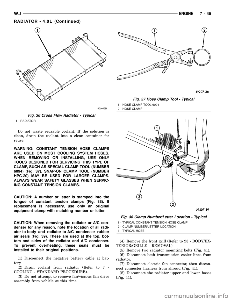
All vehicles are equipped with a cross flow type
radiator with plastic side tanks (Fig. 36).
Plastic tanks, while stronger than brass, are sub-
ject to damage by impact, such as from tools or
wrenches. Handle radiator with care.
REMOVAL
WARNING: DO NOT REMOVE THE CYLINDER
BLOCK DRAIN PLUGS OR LOOSEN THE RADIATOR
DRAINCOCK WITH THE SYSTEM HOT AND UNDER
PRESSURE. SERIOUS BURNS FROM COOLANT
CAN OCCUR. REFER TO COOLING SYSTEM DRAIN-
ING.
Fig. 35 Radiator Alignment Dowels - Typical
1 - RADIATOR
2 - ALIGNMENT DOWEL
3 - RADIATOR LOWER ISOLATOR
4 - RADIATOR LOWER CROSSMEMBER
7 - 44 ENGINEWJ
RADIATOR - 4.7L (Continued)
Page 268 of 2199
Do not waste reusable coolant. If the solution is
clean, drain the coolant into a clean container for
reuse.
WARNING: CONSTANT TENSION HOSE CLAMPS
ARE USED ON MOST COOLING SYSTEM HOSES.
WHEN REMOVING OR INSTALLING, USE ONLY
TOOLS DESIGNED FOR SERVICING THIS TYPE OF
CLAMP, SUCH AS SPECIAL CLAMP TOOL (NUMBER
6094) (Fig. 37). SNAP-ON CLAMP TOOL (NUMBER
HPC-20) MAY BE USED FOR LARGER CLAMPS.
ALWAYS WEAR SAFETY GLASSES WHEN SERVIC-
ING CONSTANT TENSION CLAMPS.
CAUTION: A number or letter is stamped into the
tongue of constant tension clamps (Fig. 38). If
replacement is necessary, use only an original
equipment clamp with matching number or letter.
CAUTION: When removing the radiator or A/C con-
denser for any reason, note the location of all radi-
ator-to-body and radiator-to-A/C condenser rubber
air seals (Fig. 39). These are used at the top, bot-
tom and sides of the radiator and A/C condenser.
To prevent overheating, these seals must be
installed to their original positions.
(1) Disconnect the negative battery cable at bat-
tery.
(2) Drain coolant from radiator (Refer to 7 -
COOLING - STANDARD PROCEDURE).
(3) Do not attempt to remove fan/viscous fan drive
assembly from vehicle at this time.(4) Remove the front grill (Refer to 23 - BODY/EX-
TERIOR/GRILLE - REMOVAL).
(5) Remove two radiator mounting bolts (Fig. 41).
(6) Disconnect both transmission cooler lines from
radiator.
(7) Disconnect electric fan connector, then discon-
nect connector harness from shroud (Fig. 41).
(8) Disconnect the radiator upper and lower hoses
(Fig. 41).
Fig. 36 Cross Flow Radiator - Typical
1 - RADIATOR
Fig. 37 Hose Clamp Tool - Typical
1 - HOSE CLAMP TOOL 6094
2 - HOSE CLAMP
Fig. 38 Clamp Number/Letter Location - Typical
1 - TYPICAL CONSTANT TENSION HOSE CLAMP
2 - CLAMP NUMBER/LETTER LOCATION
3 - TYPICAL HOSE
WJENGINE 7 - 45
RADIATOR - 4.0L (Continued)