Tools JEEP GRAND CHEROKEE 2003 WJ / 2.G Owners Manual
[x] Cancel search | Manufacturer: JEEP, Model Year: 2003, Model line: GRAND CHEROKEE, Model: JEEP GRAND CHEROKEE 2003 WJ / 2.GPages: 2199, PDF Size: 76.01 MB
Page 1496 of 2199

SPECIAL TOOLS
POWER STEERING GEAR
Puller Seal 7794-A
Slide Hammer C-637
Remover, Pitman Arm C-4150A
Handle C-4171
Driver 8277
Driver 8294
Scoket 8343
WJGEAR 19 - 19
GEAR (Continued)
Page 1503 of 2199

LINKAGE
TABLE OF CONTENTS
page page
LINKAGE
DESCRIPTION
STEERING LINKAGE ± RIGHT HAND DRIVE
(RHD) VEHICLES......................26
DESCRIPTION........................26
SPECIFICATIONS
TORQUE CHART......................28
SPECIAL TOOLS
STEERING LINKAGE...................28
DAMPER
DESCRIPTION.........................28
OPERATION...........................28
REMOVAL.............................28
INSTALLATION.........................29
DRAG LINK
DESCRIPTION.........................29OPERATION...........................29
REMOVAL.............................29
INSTALLATION.........................29
PITMAN ARM
DESCRIPTION.........................29
OPERATION...........................29
REMOVAL.............................29
INSTALLATION.........................30
TIE ROD END
DESCRIPTION.........................30
OPERATION...........................30
REMOVAL.............................30
INSTALLATION.........................30
LINKAGE
DESCRIPTION
STEERING LINKAGE ± RIGHT HAND DRIVE
(RHD) VEHICLES
Vehicles equipped with right hand drive (RHD)
steering utilize the same components of left hand
drive vehicles. The RHD Steering linkage is designed
as a mirror image of left hand drive linkage with the
exception of the steering damper (Fig. 1), which is
mounted on the same side of the vehicle weather
RHD or LHD. See figure below for reference. All
specifications are the same as LHD. Refer to Group
19, Steering of the gasoline engine service manual for
additional information.
DESCRIPTION
The steering linkage consists of a pitman arm,
drag link, tie rod, and steering dampener (Fig. 2) .
An adjustment sleeve on the tie rod is used to set
wheel toe position. The sleeve on the drag link is
used for steering wheel centering.
CAUTION: If any steering components are replaced
or serviced an alignment must be performed, to
ensure the vehicle meets all alignment specifica-
tions.
CAUTION: Components attached with a nut and cot-
ter pin must be torqued to specification. Then if the
slot in the nut does not line up with the cotter pin
hole, tighten nut until it is aligned. Never loosen the
nut to align the cotter pin hole.
19 - 26 LINKAGEWJ
Page 1505 of 2199
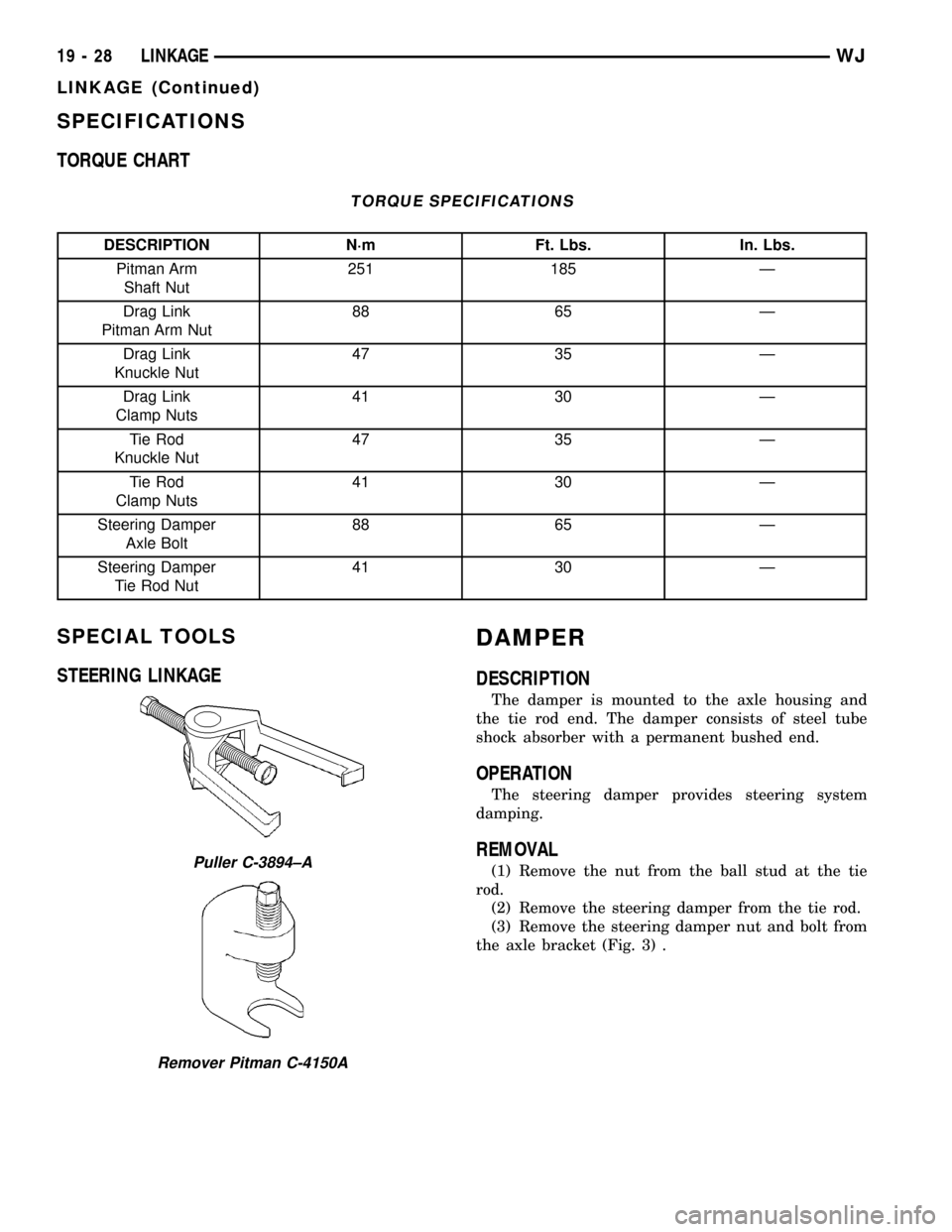
SPECIFICATIONS
TORQUE CHART
TORQUE SPECIFICATIONS
DESCRIPTION N´m Ft. Lbs. In. Lbs.
Pitman Arm
Shaft Nut251 185 Ð
Drag Link
Pitman Arm Nut88 65 Ð
Drag Link
Knuckle Nut47 35 Ð
Drag Link
Clamp Nuts41 30 Ð
Tie Rod
Knuckle Nut47 35 Ð
Tie Rod
Clamp Nuts41 30 Ð
Steering Damper
Axle Bolt88 65 Ð
Steering Damper
Tie Rod Nut41 30 Ð
SPECIAL TOOLS
STEERING LINKAGEDAMPER
DESCRIPTION
The damper is mounted to the axle housing and
the tie rod end. The damper consists of steel tube
shock absorber with a permanent bushed end.
OPERATION
The steering damper provides steering system
damping.
REMOVAL
(1) Remove the nut from the ball stud at the tie
rod.
(2) Remove the steering damper from the tie rod.
(3) Remove the steering damper nut and bolt from
the axle bracket (Fig. 3) .Puller C-3894±A
Remover Pitman C-4150A
19 - 28 LINKAGEWJ
LINKAGE (Continued)
Page 1508 of 2199

PUMP
TABLE OF CONTENTS
page page
PUMP
DESCRIPTION - 4.0L, 4.7L................32
OPERATION
OPERATION - 4.7L....................32
OPERATION - 4.0L....................32
DIAGNOSIS AND TESTING - PUMP LEAKAGE . 33
STANDARD PROCEDURE
STANDARD PROCEDURE - INITIAL
OPERATION - 4.0L....................33
STANDARD PROCEDURE - INITIAL
OPERATION - 4.7L....................33
REMOVAL
REMOVAL - 4.0L ENGINE...............34
REMOVAL - 4.7L ENGINE...............34
INSTALLATION
INSTALLATION - 4.0L ENGINE...........34
INSTALLATION - 4.7L ENGINE...........34
SPECIFICATIONS
TORQUE CHART......................35
SPECIAL TOOLS
POWER STEERING PUMP..............36
FLUID COOLER
DESCRIPTION.........................36
REMOVAL.............................36
INSTALLATION.........................37
HOSES - 4.0L
DESCRIPTION
DESCRIPTION - PRESSURE LINE........37
DESCRIPTION - RETURN LINE...........37
OPERATION
OPERATION - PRESSURE LINE..........37
OPERATION - RETURN LINE............37
REMOVAL.............................37
INSTALLATION.........................37
HOSES - 4.7L
DESCRIPTION
DESCRIPTION - 1/2º PRESSURE HOSE....38DESCRIPTION - 1/2º RETURN HOSE......38
DESCRIPTION - 3/8º PRESSURE HOSE....38
DESCRIPTION - 3/8º GEAR OUTLET HOSE . 38
DESCRIPTION - 3/8º RETURN HOSE......38
OPERATION
OPERATION - 1/2º PRESSURE HOSE......38
OPERATION - 1/2º RETURN HOSE........38
OPERATION - 3/8º PRESSURE HOSE......39
OPERATION - 3/8º GEAR OUTLET HOSE . . . 39
OPERATION - 3/8ºRETURN HOSE........39
REMOVAL
REMOVAL - 1/29PRESSURE HOSE.......39
REMOVAL - 1/29RETURN HOSE..........39
REMOVAL - 3/89PRESSURE HOSE.......39
REMOVAL - 3/89RETURN HOSE..........39
REMOVAL - 3/89GEAR OUTLET HOSE.....40
REMOVAL - INLET COOLER HOSE........40
REMOVAL - OUTLET COOLER HOSE......40
INSTALLATION
INSTALLATION - 1/29PRESSURE HOSE....40
INSTALLATION - 1/29RETURN HOSE......40
INSTALLATION - 3/89PRESSURE HOSE....41
INSTALLATION - 3/89RETURN HOSE......41
INSTALLATION - 3/89GEAR OUTLET HOSE . 41
INSTALLATION - INLET COOLER HOSE....41
INSTALLATION - OUTLET COOLER HOSE . . 41
PULLEY
DESCRIPTION
POWER STEERING PUMP PULLEY - 3.1L
DIESEL.............................41
REMOVAL.............................41
INSTALLATION.........................42
RESERVOIR
REMOVAL.............................42
INSTALLATION.........................42
WJPUMP 19 - 31
Page 1513 of 2199

SPECIAL TOOLS
POWER STEERING PUMP
FLUID COOLER
DESCRIPTION
4.7L models of this vehicle are equipped with a
cooler for the power steering system fluid. The power
steering fluid cooler is located at the front of the
vehicle. It is mounted to the radiator support just
forward of the air-conditioning condenser and just
rearward of the front fascia (Fig. 6). The cooler is
positioned so it is in the air flow through the front
fascia of the vehicle.
REMOVAL
(1) Disconnect negative battery cable at battery.
(2) Drain the power steering fluid out of the reser-
voir.
(3) Remove the front fascia grille assembly,(Refer
to 13 - FRAMES & BUMPERS/BUMPERS/FRONT
FASCIA - REMOVAL).
(4) Remove the grille opening reinforcement panel
(5) Place a drain pan under the cooler.
(6) Disconnect the lower hose at cooler (Fig. 6).
(7) Disconnect the upper hose at cooler (Fig. 6).
(8) Remove the three cooler mounting bolts (Fig.
6).
(9) Remove the cooler from the vehicle.
Analyzer Set, Power Steering Flow/Pressure 6815
Adapters, Power Steering Flow/Pressure Tester
6893
4.7L HYDRAULIC POWER STEERING TEST
ADAPTER KIT - 8630
Puller C-4333
Installer, Power Steering Pulley C-4063B
Fig. 6 POWER STEERING FLUID COOLER
1 - POWER STEERING COOLER
2 - POWER STEERING COOLER LINES CLIP
19 - 36 PUMPWJ
PUMP (Continued)
Page 1520 of 2199
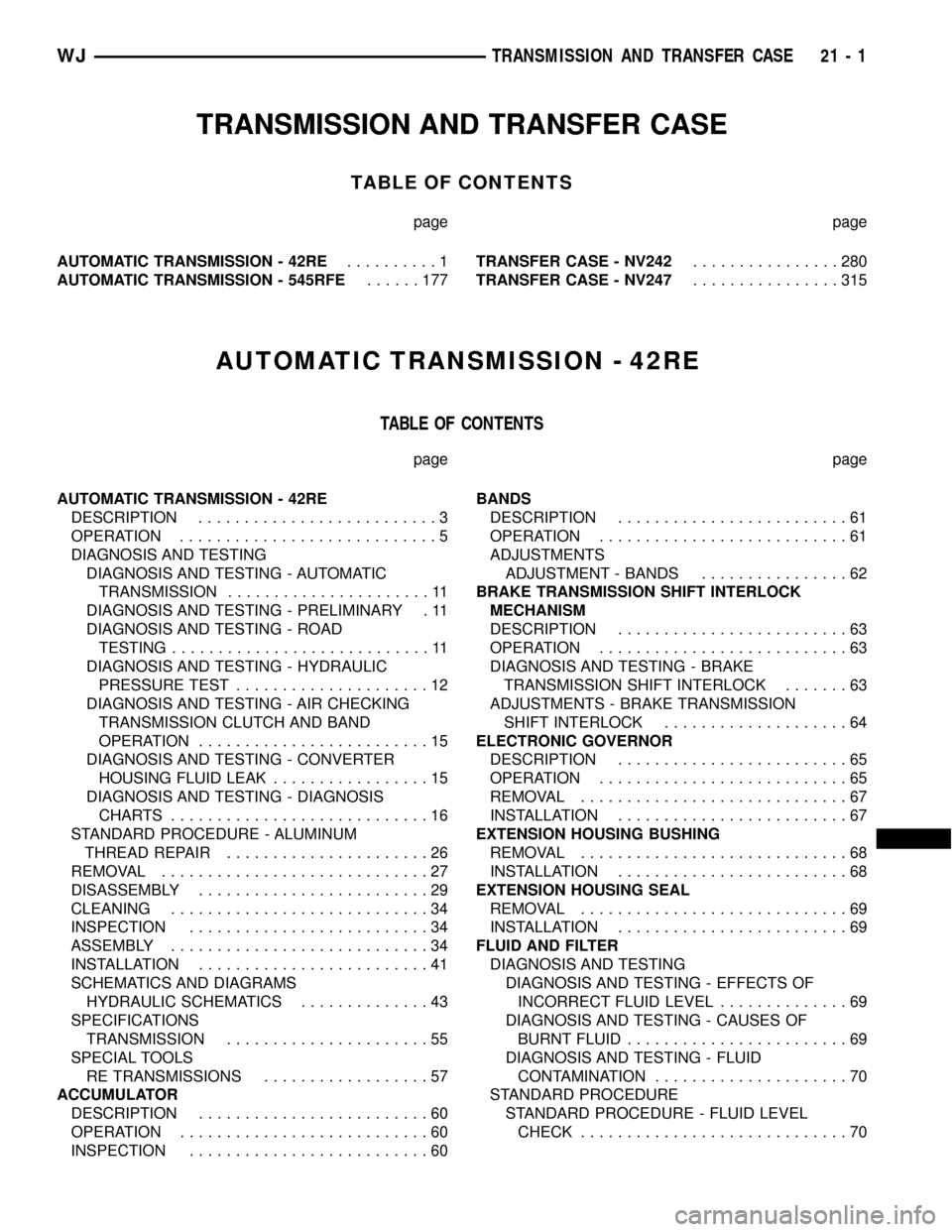
TRANSMISSION AND TRANSFER CASE
TABLE OF CONTENTS
page page
AUTOMATIC TRANSMISSION - 42RE..........1
AUTOMATIC TRANSMISSION - 545RFE......177TRANSFER CASE - NV242................280
TRANSFER CASE - NV247................315
AUTOMATIC TRANSMISSION - 42RE
TABLE OF CONTENTS
page page
AUTOMATIC TRANSMISSION - 42RE
DESCRIPTION..........................3
OPERATION............................5
DIAGNOSIS AND TESTING
DIAGNOSIS AND TESTING - AUTOMATIC
TRANSMISSION......................11
DIAGNOSIS AND TESTING - PRELIMINARY . 11
DIAGNOSIS AND TESTING - ROAD
TESTING............................11
DIAGNOSIS AND TESTING - HYDRAULIC
PRESSURE TEST.....................12
DIAGNOSIS AND TESTING - AIR CHECKING
TRANSMISSION CLUTCH AND BAND
OPERATION.........................15
DIAGNOSIS AND TESTING - CONVERTER
HOUSING FLUID LEAK.................15
DIAGNOSIS AND TESTING - DIAGNOSIS
CHARTS............................16
STANDARD PROCEDURE - ALUMINUM
THREAD REPAIR......................26
REMOVAL.............................27
DISASSEMBLY.........................29
CLEANING............................34
INSPECTION..........................34
ASSEMBLY............................34
INSTALLATION.........................41
SCHEMATICS AND DIAGRAMS
HYDRAULIC SCHEMATICS..............43
SPECIFICATIONS
TRANSMISSION......................55
SPECIAL TOOLS
RE TRANSMISSIONS..................57
ACCUMULATOR
DESCRIPTION.........................60
OPERATION...........................60
INSPECTION..........................60BANDS
DESCRIPTION.........................61
OPERATION...........................61
ADJUSTMENTS
ADJUSTMENT - BANDS................62
BRAKE TRANSMISSION SHIFT INTERLOCK
MECHANISM
DESCRIPTION.........................63
OPERATION...........................63
DIAGNOSIS AND TESTING - BRAKE
TRANSMISSION SHIFT INTERLOCK.......63
ADJUSTMENTS - BRAKE TRANSMISSION
SHIFT INTERLOCK....................64
ELECTRONIC GOVERNOR
DESCRIPTION.........................65
OPERATION...........................65
REMOVAL.............................67
INSTALLATION.........................67
EXTENSION HOUSING BUSHING
REMOVAL.............................68
INSTALLATION.........................68
EXTENSION HOUSING SEAL
REMOVAL.............................69
INSTALLATION.........................69
FLUID AND FILTER
DIAGNOSIS AND TESTING
DIAGNOSIS AND TESTING - EFFECTS OF
INCORRECT FLUID LEVEL..............69
DIAGNOSIS AND TESTING - CAUSES OF
BURNT FLUID........................69
DIAGNOSIS AND TESTING - FLUID
CONTAMINATION.....................70
STANDARD PROCEDURE
STANDARD PROCEDURE - FLUID LEVEL
CHECK.............................70
WJTRANSMISSION AND TRANSFER CASE 21 - 1
Page 1545 of 2199
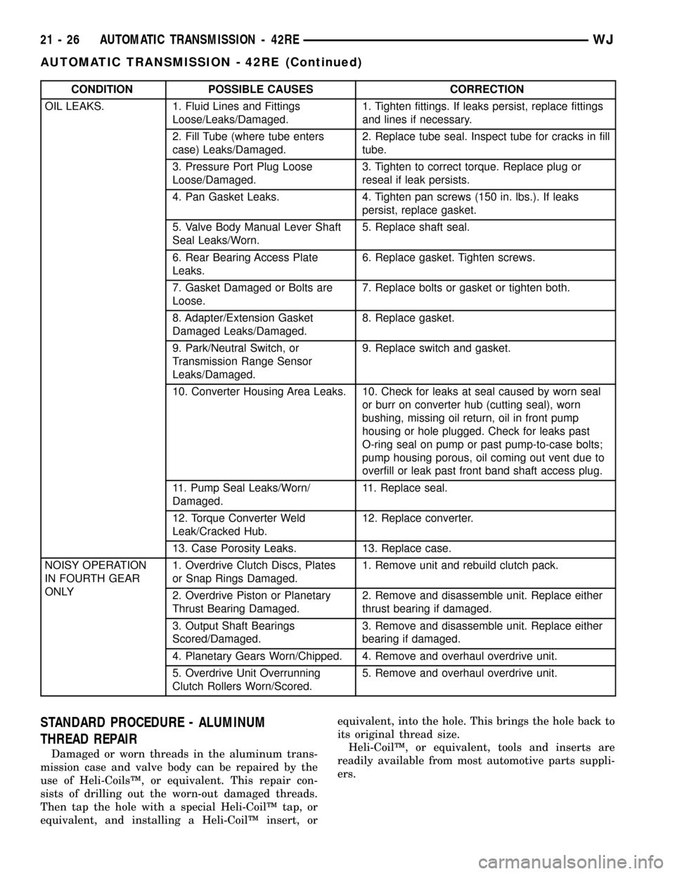
CONDITION POSSIBLE CAUSES CORRECTION
OIL LEAKS. 1. Fluid Lines and Fittings
Loose/Leaks/Damaged.1. Tighten fittings. If leaks persist, replace fittings
and lines if necessary.
2. Fill Tube (where tube enters
case) Leaks/Damaged.2. Replace tube seal. Inspect tube for cracks in fill
tube.
3. Pressure Port Plug Loose
Loose/Damaged.3. Tighten to correct torque. Replace plug or
reseal if leak persists.
4. Pan Gasket Leaks. 4. Tighten pan screws (150 in. lbs.). If leaks
persist, replace gasket.
5. Valve Body Manual Lever Shaft
Seal Leaks/Worn.5. Replace shaft seal.
6. Rear Bearing Access Plate
Leaks.6. Replace gasket. Tighten screws.
7. Gasket Damaged or Bolts are
Loose.7. Replace bolts or gasket or tighten both.
8. Adapter/Extension Gasket
Damaged Leaks/Damaged.8. Replace gasket.
9. Park/Neutral Switch, or
Transmission Range Sensor
Leaks/Damaged.9. Replace switch and gasket.
10. Converter Housing Area Leaks. 10. Check for leaks at seal caused by worn seal
or burr on converter hub (cutting seal), worn
bushing, missing oil return, oil in front pump
housing or hole plugged. Check for leaks past
O-ring seal on pump or past pump-to-case bolts;
pump housing porous, oil coming out vent due to
overfill or leak past front band shaft access plug.
11. Pump Seal Leaks/Worn/
Damaged.11. Replace seal.
12. Torque Converter Weld
Leak/Cracked Hub.12. Replace converter.
13. Case Porosity Leaks. 13. Replace case.
NOISY OPERATION
IN FOURTH GEAR
ONLY1. Overdrive Clutch Discs, Plates
or Snap Rings Damaged.1. Remove unit and rebuild clutch pack.
2. Overdrive Piston or Planetary
Thrust Bearing Damaged.2. Remove and disassemble unit. Replace either
thrust bearing if damaged.
3. Output Shaft Bearings
Scored/Damaged.3. Remove and disassemble unit. Replace either
bearing if damaged.
4. Planetary Gears Worn/Chipped. 4. Remove and overhaul overdrive unit.
5. Overdrive Unit Overrunning
Clutch Rollers Worn/Scored.5. Remove and overhaul overdrive unit.
STANDARD PROCEDURE - ALUMINUM
THREAD REPAIR
Damaged or worn threads in the aluminum trans-
mission case and valve body can be repaired by the
use of Heli-CoilsŸ, or equivalent. This repair con-
sists of drilling out the worn-out damaged threads.
Then tap the hole with a special Heli-CoilŸ tap, or
equivalent, and installing a Heli-CoilŸ insert, orequivalent, into the hole. This brings the hole back to
its original thread size.
Heli-CoilŸ, or equivalent, tools and inserts are
readily available from most automotive parts suppli-
ers.
21 - 26 AUTOMATIC TRANSMISSION - 42REWJ
AUTOMATIC TRANSMISSION - 42RE (Continued)
Page 1549 of 2199
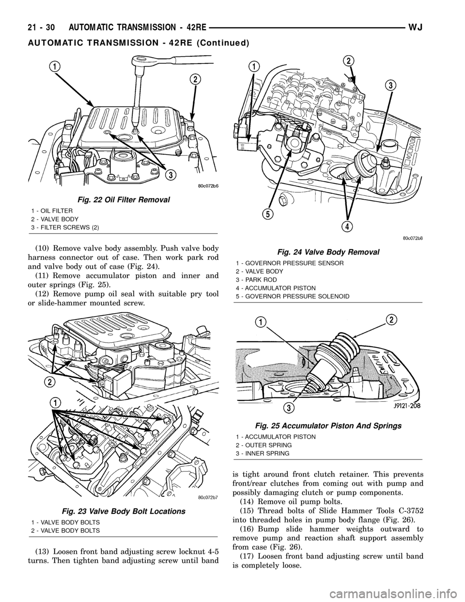
(10) Remove valve body assembly. Push valve body
harness connector out of case. Then work park rod
and valve body out of case (Fig. 24).
(11) Remove accumulator piston and inner and
outer springs (Fig. 25).
(12) Remove pump oil seal with suitable pry tool
or slide-hammer mounted screw.
(13) Loosen front band adjusting screw locknut 4-5
turns. Then tighten band adjusting screw until bandis tight around front clutch retainer. This prevents
front/rear clutches from coming out with pump and
possibly damaging clutch or pump components.
(14) Remove oil pump bolts.
(15) Thread bolts of Slide Hammer Tools C-3752
into threaded holes in pump body flange (Fig. 26).
(16) Bump slide hammer weights outward to
remove pump and reaction shaft support assembly
from case (Fig. 26).
(17) Loosen front band adjusting screw until band
is completely loose.
Fig. 22 Oil Filter Removal
1 - OIL FILTER
2 - VALVE BODY
3 - FILTER SCREWS (2)
Fig. 23 Valve Body Bolt Locations
1 - VALVE BODY BOLTS
2 - VALVE BODY BOLTS
Fig. 24 Valve Body Removal
1 - GOVERNOR PRESSURE SENSOR
2 - VALVE BODY
3 - PARK ROD
4 - ACCUMULATOR PISTON
5 - GOVERNOR PRESSURE SOLENOID
Fig. 25 Accumulator Piston And Springs
1 - ACCUMULATOR PISTON
2 - OUTER SPRING
3 - INNER SPRING
21 - 30 AUTOMATIC TRANSMISSION - 42REWJ
AUTOMATIC TRANSMISSION - 42RE (Continued)
Page 1550 of 2199
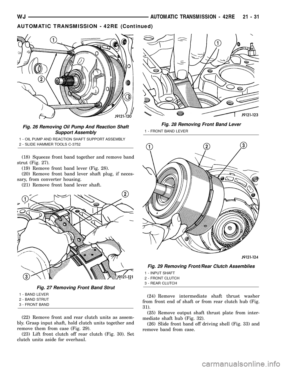
(18) Squeeze front band together and remove band
strut (Fig. 27).
(19) Remove front band lever (Fig. 28).
(20) Remove front band lever shaft plug, if neces-
sary, from converter housing.
(21) Remove front band lever shaft.
(22) Remove front and rear clutch units as assem-
bly. Grasp input shaft, hold clutch units together and
remove them from case (Fig. 29).
(23) Lift front clutch off rear clutch (Fig. 30). Set
clutch units aside for overhaul.(24) Remove intermediate shaft thrust washer
from front end of shaft or from rear clutch hub (Fig.
31).
(25) Remove output shaft thrust plate from inter-
mediate shaft hub (Fig. 32).
(26) Slide front band off driving shell (Fig. 33) and
remove band from case.
Fig. 26 Removing Oil Pump And Reaction Shaft
Support Assembly
1 - OIL PUMP AND REACTION SHAFT SUPPORT ASSEMBLY
2 - SLIDE HAMMER TOOLS C-3752
Fig. 27 Removing Front Band Strut
1 - BAND LEVER
2 - BAND STRUT
3 - FRONT BAND
Fig. 28 Removing Front Band Lever
1 - FRONT BAND LEVER
Fig. 29 Removing Front/Rear Clutch Assemblies
1 - INPUT SHAFT
2 - FRONT CLUTCH
3 - REAR CLUTCH
WJAUTOMATIC TRANSMISSION - 42RE 21 - 31
AUTOMATIC TRANSMISSION - 42RE (Continued)
Page 1552 of 2199
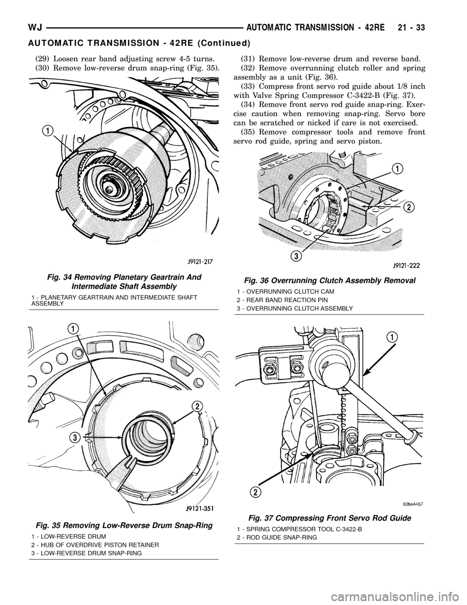
(29) Loosen rear band adjusting screw 4-5 turns.
(30) Remove low-reverse drum snap-ring (Fig. 35).(31) Remove low-reverse drum and reverse band.
(32) Remove overrunning clutch roller and spring
assembly as a unit (Fig. 36).
(33) Compress front servo rod guide about 1/8 inch
with Valve Spring Compressor C-3422-B (Fig. 37).
(34) Remove front servo rod guide snap-ring. Exer-
cise caution when removing snap-ring. Servo bore
can be scratched or nicked if care is not exercised.
(35) Remove compressor tools and remove front
servo rod guide, spring and servo piston.
Fig. 34 Removing Planetary Geartrain And
Intermediate Shaft Assembly
1 - PLANETARY GEARTRAIN AND INTERMEDIATE SHAFT
ASSEMBLY
Fig. 35 Removing Low-Reverse Drum Snap-Ring
1 - LOW-REVERSE DRUM
2 - HUB OF OVERDRIVE PISTON RETAINER
3 - LOW-REVERSE DRUM SNAP-RING
Fig. 36 Overrunning Clutch Assembly Removal
1 - OVERRUNNING CLUTCH CAM
2 - REAR BAND REACTION PIN
3 - OVERRUNNING CLUTCH ASSEMBLY
Fig. 37 Compressing Front Servo Rod Guide
1 - SPRING COMPRESSOR TOOL C-3422-B
2 - ROD GUIDE SNAP-RING
WJAUTOMATIC TRANSMISSION - 42RE 21 - 33
AUTOMATIC TRANSMISSION - 42RE (Continued)