drain JEEP GRAND CHEROKEE 2003 WJ / 2.G Owners Manual
[x] Cancel search | Manufacturer: JEEP, Model Year: 2003, Model line: GRAND CHEROKEE, Model: JEEP GRAND CHEROKEE 2003 WJ / 2.GPages: 2199, PDF Size: 76.01 MB
Page 1493 of 2199

GEAR
TABLE OF CONTENTS
page page
GEAR
DESCRIPTION.........................16
OPERATION...........................16
REMOVAL.............................16
INSTALLATION.........................16
ADJUSTMENTS
STEERING GEAR.....................18
SPECIFICATIONS
POWER STEERING GEAR..............18
SPECIAL TOOLS
POWER STEERING GEAR..............19
PITMAN SHAFT
REMOVAL.............................20INSTALLATION.........................20
PITMAN SHAFT BEARING
REMOVAL.............................22
INSTALLATION.........................22
PITMAN SHAFT SEAL
REMOVAL.............................22
INSTALLATION.........................23
RACK PISTON/VALVE ASSEMBLY
REMOVAL.............................23
INSTALLATION.........................25
STUB SHAFT HOUSING
REMOVAL.............................25
INSTALLATION.........................25
GEAR
DESCRIPTION
The power steering gear is a recirculating ball type
gear (Fig. 1) .
The following gear components can be serviced:
²Pitman Shaft and Cover
²Pitman Shaft Bearings
²Pitman Shaft Oil Seal/Dust Seal
²Stud Shaft Housing with Seal
²O-Rings and Teflon Rings
NOTE: If rack piston assembly is damaged the gear
must be replaced.
OPERATION
The gear acts as a rolling thread between the
worm shaft and rack piston. The worm shaft is sup-
ported by a thrust bearing at the lower end and a
bearing assembly at the upper end. When the worm
shaft is turned the rack piston moves. The rack pis-
ton teeth mesh with the pitman shaft. Turning the
worm shaft turns the pitman shaft, which turns the
steering linkage.
REMOVAL
(1) Place the front wheels in the straight ahead
position with the steering wheel centered and locked.
(2) Remove the air cleaner housing,(Refer to 9 -
ENGINE/AIR INTAKE SYSTEM/AIR CLEANER
HOUSING - REMOVAL).
(3) Drain or siphon the power steering system.(4) Remove the pressure and return lines (Fig.
2)from the steering gear. Refer to hose removal in
this section.
(5) Remove the column coupler shaft bolt (Fig.
2)and remove the shaft from the gear.
(6) Raise and support the vehicle.
(7) Remove the left front wheel and tire assembly.
(8) Remove the pitman arm from gear with Puller
C-4150A.
(9) Remove the windshield washer reservoir,(Refer
to 8 - ELECTRICAL/WIPERS/WASHERS/WASHER
RESERVOIR - REMOVAL).
(10) Remove the steering gear mounting bolts.
Remove the steering gear out of the engine compart-
ment (Fig. 3).
INSTALLATION
(1) Position the steering gear on the frame rail and
install the bolts. Tighten the bolts to 108 N´m (80 ft.
lbs.) torque.
(2) Install the pitman arm and tighten nut to 251
N´m (185 ft. lbs.).
(3) Install windshield washer reservoir,(Refer to 8 -
ELECTRICAL/WIPERS/WASHERS/WASHER RES-
ERVOIR - INSTALLATION).
(4) Install the wheel and tire assembly.
(5) Remove the support and lower the vehicle.
(6) Install the pressure and return hoses to the
steering gear and tighten to 20-38 N´m (14-28 ft.
lbs.).
(7) Install the column coupler shaft.
(8) Install the air cleaner housing,(Refer to 9 -
ENGINE/AIR INTAKE SYSTEM/AIR CLEANER
HOUSING - INSTALLATION).
19 - 16 GEARWJ
Page 1495 of 2199

ADJUSTMENTS
STEERING GEAR
NOTE: Adjusting the steering gear in the vehicle is
not recommended. Remove gear from the vehicle
and drain the fluid. Then mount gear in a vise to
perform adjustments.
OVER-CENTER
(1) Rotate the stub shaft with Socket 8343 from
stop to stop and count the number of turns.
(2) Center the stub shaft by rotating it from the
stop 1/2 of the total amount of turns.
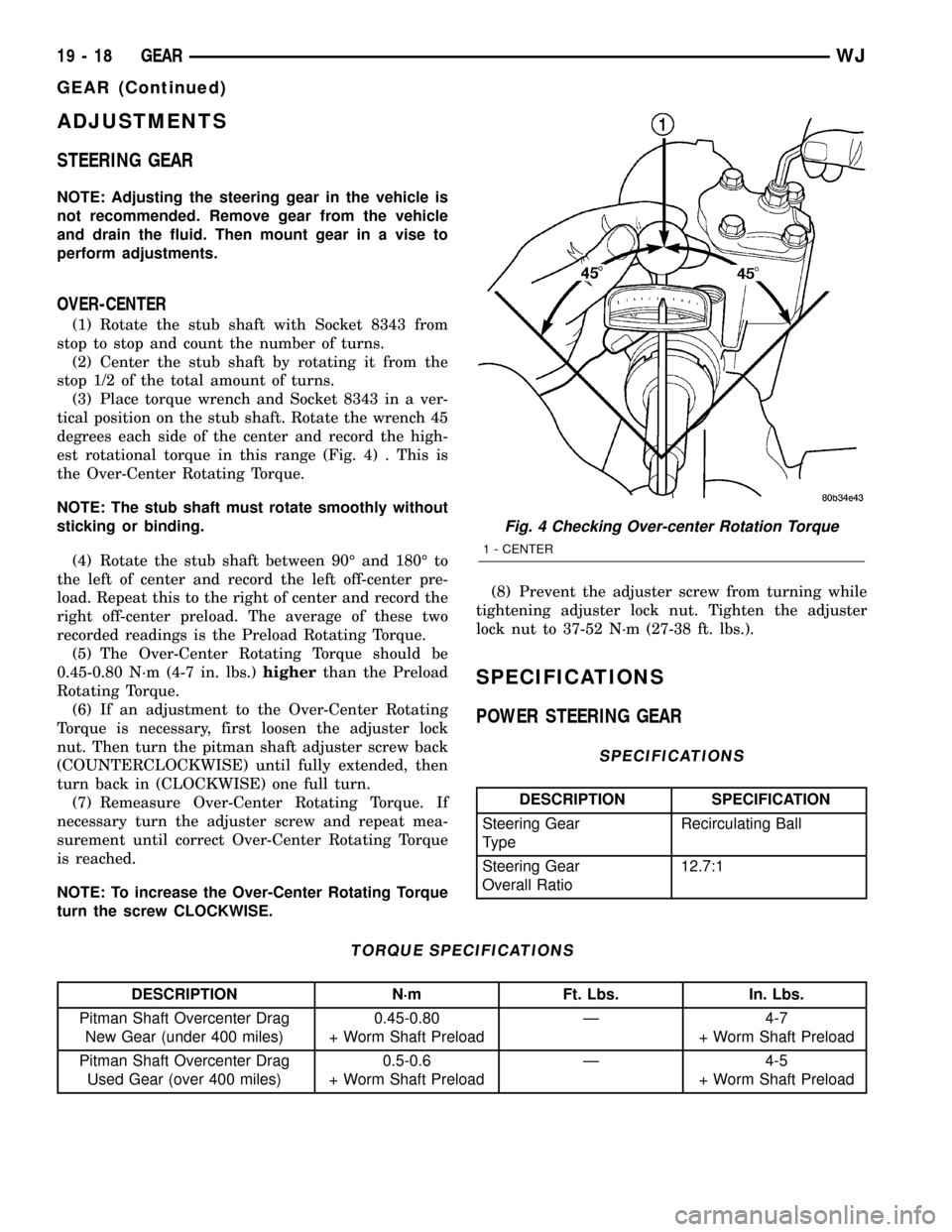
(3) Place torque wrench and Socket 8343 in a ver-
tical position on the stub shaft. Rotate the wrench 45
degrees each side of the center and record the high-
est rotational torque in this range (Fig. 4) . This is
the Over-Center Rotating Torque.
NOTE: The stub shaft must rotate smoothly without
sticking or binding.
(4) Rotate the stub shaft between 90É and 180É to
the left of center and record the left off-center pre-
load. Repeat this to the right of center and record the
right off-center preload. The average of these two
recorded readings is the Preload Rotating Torque.
(5) The Over-Center Rotating Torque should be
0.45-0.80 N´m (4-7 in. lbs.)higherthan the Preload
Rotating Torque.
(6) If an adjustment to the Over-Center Rotating
Torque is necessary, first loosen the adjuster lock
nut. Then turn the pitman shaft adjuster screw back
(COUNTERCLOCKWISE) until fully extended, then
turn back in (CLOCKWISE) one full turn.
(7) Remeasure Over-Center Rotating Torque. If
necessary turn the adjuster screw and repeat mea-
surement until correct Over-Center Rotating Torque
is reached.
NOTE: To increase the Over-Center Rotating Torque
turn the screw CLOCKWISE.(8) Prevent the adjuster screw from turning while
tightening adjuster lock nut. Tighten the adjuster
lock nut to 37-52 N´m (27-38 ft. lbs.).
SPECIFICATIONS
POWER STEERING GEAR
SPECIFICATIONS
DESCRIPTION SPECIFICATION
Steering Gear
TypeRecirculating Ball
Steering Gear
Overall Ratio12.7:1
TORQUE SPECIFICATIONS
DESCRIPTION N´m Ft. Lbs. In. Lbs.
Pitman Shaft Overcenter Drag
New Gear (under 400 miles)0.45-0.80
+ Worm Shaft PreloadÐ 4-7
+ Worm Shaft Preload
Pitman Shaft Overcenter Drag
Used Gear (over 400 miles)0.5-0.6
+ Worm Shaft PreloadÐ 4-5
+ Worm Shaft Preload
Fig. 4 Checking Over-center Rotation Torque
1 - CENTER
19 - 18 GEARWJ
GEAR (Continued)
Page 1511 of 2199

(11) While the vehicle is in park, use the DRB III
to activate the hydraulic fan to full fan operation and
briefly rev the engine up to 3000 rpm to fully engage
the hydraulic fan.
(12) Check the fluid level add if necessary.
REMOVAL
REMOVAL - 4.0L ENGINE
(1) Remove serpentine drive belt,(Refer to 7 -
COOLING/ACCESSORY DRIVE/DRIVE BELTS -
REMOVAL).
(2) Remove pressure and return hoses from pump
and drain the pump.
(3)
Loosen the pump bracket bolt at the engine block.
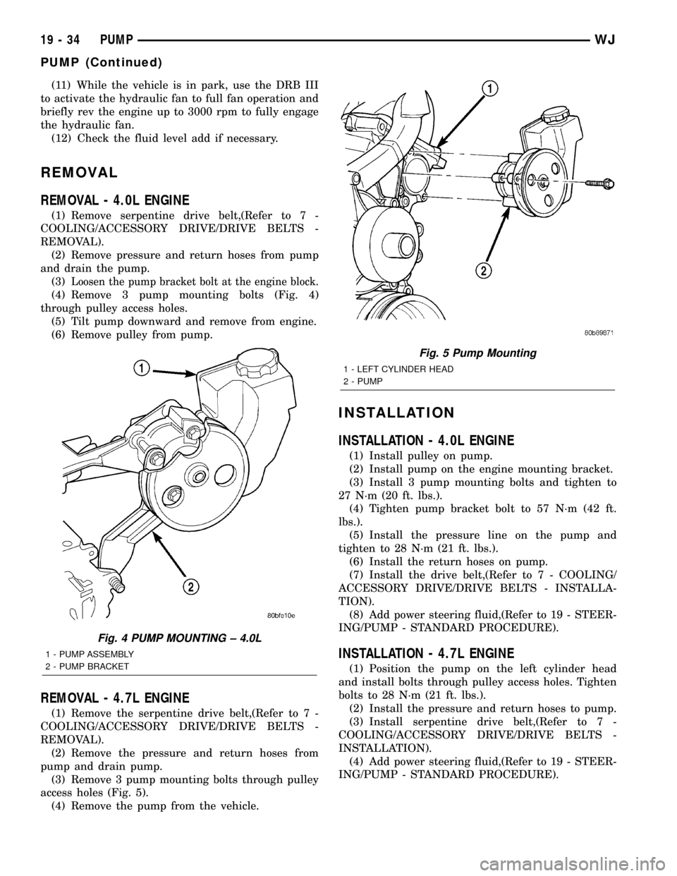
(4) Remove 3 pump mounting bolts (Fig. 4)
through pulley access holes.
(5) Tilt pump downward and remove from engine.
(6) Remove pulley from pump.
REMOVAL - 4.7L ENGINE
(1) Remove the serpentine drive belt,(Refer to 7 -
COOLING/ACCESSORY DRIVE/DRIVE BELTS -
REMOVAL).
(2) Remove the pressure and return hoses from
pump and drain pump.
(3) Remove 3 pump mounting bolts through pulley
access holes (Fig. 5).
(4) Remove the pump from the vehicle.
INSTALLATION
INSTALLATION - 4.0L ENGINE
(1) Install pulley on pump.
(2) Install pump on the engine mounting bracket.
(3) Install 3 pump mounting bolts and tighten to
27 N´m (20 ft. lbs.).
(4) Tighten pump bracket bolt to 57 N´m (42 ft.
lbs.).
(5) Install the pressure line on the pump and
tighten to 28 N´m (21 ft. lbs.).
(6) Install the return hoses on pump.
(7) Install the drive belt,(Refer to 7 - COOLING/
ACCESSORY DRIVE/DRIVE BELTS - INSTALLA-
TION).
(8) Add power steering fluid,(Refer to 19 - STEER-
ING/PUMP - STANDARD PROCEDURE).
INSTALLATION - 4.7L ENGINE
(1) Position the pump on the left cylinder head
and install bolts through pulley access holes. Tighten
bolts to 28 N´m (21 ft. lbs.).
(2) Install the pressure and return hoses to pump.
(3) Install serpentine drive belt,(Refer to 7 -
COOLING/ACCESSORY DRIVE/DRIVE BELTS -
INSTALLATION).
(4) Add power steering fluid,(Refer to 19 - STEER-
ING/PUMP - STANDARD PROCEDURE).
Fig. 4 PUMP MOUNTING ± 4.0L
1 - PUMP ASSEMBLY
2 - PUMP BRACKET
Fig. 5 Pump Mounting
1 - LEFT CYLINDER HEAD
2 - PUMP
19 - 34 PUMPWJ
PUMP (Continued)
Page 1513 of 2199

SPECIAL TOOLS
POWER STEERING PUMP
FLUID COOLER
DESCRIPTION
4.7L models of this vehicle are equipped with a
cooler for the power steering system fluid. The power
steering fluid cooler is located at the front of the
vehicle. It is mounted to the radiator support just
forward of the air-conditioning condenser and just
rearward of the front fascia (Fig. 6). The cooler is
positioned so it is in the air flow through the front
fascia of the vehicle.
REMOVAL
(1) Disconnect negative battery cable at battery.
(2) Drain the power steering fluid out of the reser-
voir.
(3) Remove the front fascia grille assembly,(Refer
to 13 - FRAMES & BUMPERS/BUMPERS/FRONT
FASCIA - REMOVAL).
(4) Remove the grille opening reinforcement panel
(5) Place a drain pan under the cooler.
(6) Disconnect the lower hose at cooler (Fig. 6).
(7) Disconnect the upper hose at cooler (Fig. 6).
(8) Remove the three cooler mounting bolts (Fig.
6).
(9) Remove the cooler from the vehicle.
Analyzer Set, Power Steering Flow/Pressure 6815
Adapters, Power Steering Flow/Pressure Tester
6893
4.7L HYDRAULIC POWER STEERING TEST
ADAPTER KIT - 8630
Puller C-4333
Installer, Power Steering Pulley C-4063B
Fig. 6 POWER STEERING FLUID COOLER
1 - POWER STEERING COOLER
2 - POWER STEERING COOLER LINES CLIP
19 - 36 PUMPWJ
PUMP (Continued)
Page 1514 of 2199

INSTALLATION
(1) Position and install the power steering cooler
to the vehicle.
(2) Install the three mounting bracket bolts (Fig.
6).
(3) Reconnect the upper hose at cooler (Fig. 6).
(4) Reconnect the lower hose at cooler (Fig. 6).
(5) Connect negative battery cable to battery.
(6) Refill the power steering fluid and bleed the
system,(Refer to 19 - STEERING/PUMP - STAN-
DARD PROCEDURE).
(7) Start engine and check for leaks.
(8) Install the grille opening reinforcement panel
(9) Install the front fascia grille,(Refer to 13 -
FRAMES & BUMPERS/BUMPERS/FRONT FASCIA
- INSTALLATION).
HOSES - 4.0L
DESCRIPTION
DESCRIPTION - PRESSURE LINE
The hose consists of two metal ends and rubber
center section that contains a tuning cable. The
pump end uses a quick connect fitting. Lubircation
must be used on the quick connect nut and o-ring
when installing.
DESCRIPTION - RETURN LINE
Power steering return line is a hose which is
clamped at the pump and the gear.
OPERATION
OPERATION - PRESSURE LINE
Power steering pressure line, is used to transfer
high pressure power steering fluid, from the power
steering pump to the power steering gear on the
4.0L. The 4.7L power steering pressure line, is used
to transfer high pressure power steering fluid, from
the power steering pump to the engine cooling fan
and the steering gear.
OPERATION - RETURN LINE
Power steering return line, is used to transfer low
pressure power steering fluid, from the power steer-
ing gear to the power steering pump.
REMOVAL
(1) Drain the power steering fluid from the reser-
voir.
(2) Remove the air box,(Refer to 9 - ENGINE/AIR
INTAKE SYSTEM/AIR CLEANER HOUSING -
REMOVAL).
(3) Disconnect the power steering pressure hose
from the power steering pump and then the power
steering gear (Fig. 7).
(4) Disconnect the power steering return hose from
the power steering cooler and the reservoir.
(5) Remove the hoses from the vehicle.
INSTALLATION
(1) Install the hoses to the vehicle.
(2) Reconnect the power steering return hose to
the power steering cooler and the reservoir.
(3) Reconnect the power steering pressure hose to
the power steering pump and then the power steer-
ing gear.
(4) Install the air box,(Refer to 9 - ENGINE/AIR
INTAKE SYSTEM/AIR CLEANER HOUSING -
INSTALLATION).
(5) Refill the power steering fluid and bleed the
system,(Refer to 19 - STEERING/PUMP - STAN-
DARD PROCEDURE).
Fig. 7 POWER STEERING HOSES
1 - RETURN HOSE
2 - HIGH PRESSURE HOSE
3 - STEERING GEAR
WJPUMP 19 - 37
FLUID COOLER (Continued)
Page 1516 of 2199

OPERATION - 3/8º PRESSURE HOSE
High pressure power steering fluid is transmitted
from the hydraulic fan motor to the steering gear by
the 3/8º steering line.
OPERATION - 3/8º GEAR OUTLET HOSE
The gear outlet hose transmits power steering fluid
under moderate low pressure to the power steering
cooler inlet tube.
OPERATION - 3/8ºRETURN HOSE
Low pressure power steering fluid is transmitted
from the steering cooler back to the power steering
pump by the 3/8º return hose.
REMOVAL
REMOVAL - 1/2(PRESSURE HOSE
(1)Drain the power steering fluid from the reservoir.
(2) Remove the air box,(Refer to 9 - ENGINE/AIR
INTAKE SYSTEM/AIR CLEANER HOUSING -
REMOVAL).
(3) Raise and support the vehicle.
(4) Remove the metal skid plate.
(5) Disconnect the high pressure hose from the
hydraulic fan motor (Fig. 8).
(6) Disconnect the high pressure hose from the
power steering pump (Fig. 8).
(7) Remove the hose from the clipped position on
the fan shroud.
(8) Remove the hose from the vehicle.
REMOVAL - 1/2(RETURN HOSE
(1) Drain the power steering fluid from the reser-
voir.
(2) Remove the air box,(Refer to 9 - ENGINE/AIR
INTAKE SYSTEM/AIR CLEANER HOUSING -
REMOVAL).
(3) Raise and support the vehicle.
(4) Remove the metal skid plate.
(5) Disconnect the rubber return hose from the
hydraulic fan motor (Fig. 9).
(6) Disconnect the rubber return hose from the
power steering reservoir .
(7) Remove the hose from the vehicle.
REMOVAL - 3/8(PRESSURE HOSE
(1) Drain the power steering fluid from the reser-
voir.
(2) Remove the air box,(Refer to 9 - ENGINE/AIR
INTAKE SYSTEM/AIR CLEANER HOUSING -
REMOVAL).
(3) Raise and support the vehicle.
(4) Remove the metal skid plate.
(5) Disconnect the high pressure hose from the
hydraulic fan motor (Fig. 10).
(6) Disconnect the high pressure hose from the
power steering gear (Fig. 10).
(7) Remove the hose from the clipped position on
the fan shroud.
(8) Remove the hose from the vehicle.
REMOVAL - 3/8(RETURN HOSE
(1) Drain the power steering fluid from the reser-
voir.
(2) Remove the air box,(Refer to 9 - ENGINE/AIR
INTAKE SYSTEM/AIR CLEANER HOUSING -
REMOVAL).
(3) Raise and support the vehicle.
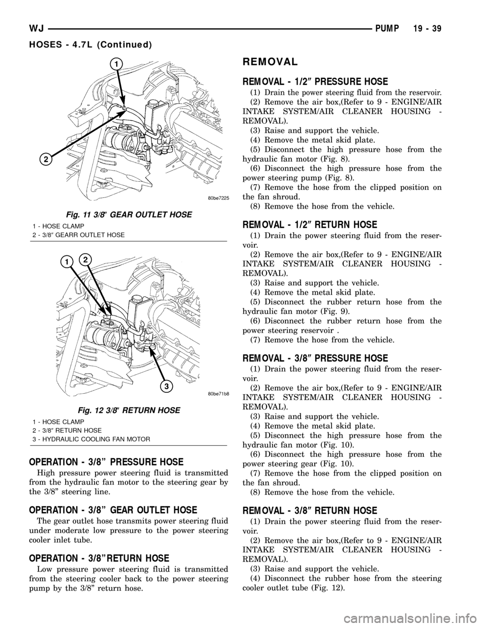
(4) Disconnect the rubber hose from the steering
cooler outlet tube (Fig. 12).
Fig. 11 3/8(GEAR OUTLET HOSE
1 - HOSE CLAMP
2 - 3/89GEARR OUTLET HOSE
Fig. 12 3/8(RETURN HOSE
1 - HOSE CLAMP
2 - 3/89RETURN HOSE
3 - HYDRAULIC COOLING FAN MOTOR
WJPUMP 19 - 39
HOSES - 4.7L (Continued)
Page 1517 of 2199

(5) Disconnect the rubber hose from the power
steering reservoir (Fig. 12).
(6) Remove the hose from the vehicle.
REMOVAL - 3/8(GEAR OUTLET HOSE
(1) Drain the power steering fluid from the reser-
voir.
(2) Remove the air box,(Refer to 9 - ENGINE/AIR
INTAKE SYSTEM/AIR CLEANER HOUSING -
REMOVAL).
(3) Raise and support the vehicle.
(4) Disconnect the rubber hose from the steering
cooler inlet tube (Fig. 11).
(5) Disconnect the metal tube from the power
steering gear (Fig. 11).
(6) Remove the hose from the vehicle.
REMOVAL - INLET COOLER HOSE
(1) Disconnect negative battery cable at battery.
(2) Drain the power steering fluid out of the reser-
voir.
(3) Remove the air box,(Refer to 9 - ENGINE/AIR
INTAKE SYSTEM/AIR CLEANER HOUSING -
REMOVAL).
(4) Remove the front fascia grille assembly,(Refer
to 13 - FRAMES & BUMPERS/BUMPERS/FRONT
FASCIA - REMOVAL).
(5) Remove the grille opening reinforcement panel
(6) Place a drain pan under the cooler.
(7) Disconnect the lower hose at cooler (Fig. 6).
(8) Disconnect the cooler hose at the gear.
(9) Remove the bracket holding the cooler hoses
(Fig. 13).
(10) Remove the cooler hose from the vehicle.
REMOVAL - OUTLET COOLER HOSE
(1) Disconnect negative battery cable at battery.
(2) Drain the power steering fluid out of the reser-
voir.
(3) Remove the air box,(Refer to 9 - ENGINE/AIR
INTAKE SYSTEM/AIR CLEANER HOUSING -
REMOVAL).
(4) Remove the front fascia grille assembly,(Refer
to 13 - FRAMES & BUMPERS/BUMPERS/FRONT
FASCIA - REMOVAL).
(5) Remove the grille opening reinforcement panel
(6) Place a drain pan under the cooler.
(7) Disconnect the upper hose at cooler (Fig. 6).
(8) Disconnect the cooler hose at the reservoir.
(9) Remove the bracket holding the cooler hoses
(Fig. 13).
(10) Remove the cooler hose from the vehicle.
INSTALLATION
INSTALLATION - 1/2(PRESSURE HOSE
NOTE: Lubrication and a new o-ring must be used
when reinstalling.
(1) Install the hoses to the vehicle.
(2) Reconnect the high pressure hose to the power
steering pump (Fig. 8) Tighten the hose to 22.5 N´m
(17 ft.lbs.).
(3) Reconnect the high pressure hose to the
hydraulic fan motor (Fig. 8) Tighten the hose to 22.5
N´m (17 ft.lbs.).
(4) Install the hose to the clipped position on the
fan shroud.
(5) Install the metal skid plate.
(6) Install the air box,(Refer to 9 - ENGINE/AIR
INTAKE SYSTEM/AIR CLEANER HOUSING -
INSTALLATION).
(7) Refill the power steering fluid and bleed the
system,(Refer to 19 - STEERING/PUMP - STAN-
DARD PROCEDURE).
INSTALLATION - 1/2(RETURN HOSE
(1) Install the hoses to the vehicle.
(2) Reconnect the rubber return hose to the power
steering reservoir (Fig. 9) Tighten the hose clamp.
(3) Reconnect the rubber return hose to the
hydraulic fan motor (Fig. 9) Tighten the hose.
(4) Install the metal skid plate.
(5) Install the air box,(Refer to 9 - ENGINE/AIR
INTAKE SYSTEM/AIR CLEANER HOUSING -
INSTALLATION).
(6) Refill the power steering fluid and bleed the
system,(Refer to 19 - STEERING/PUMP - STAN-
DARD PROCEDURE).
Fig. 13 COOLER HOSES MOUNTING BRACKET
1 - RADIATOR
2 - COOLER HOSES MOUNTING BRACKET
2 - COOLER HOSE
19 - 40 PUMPWJ
HOSES - 4.7L (Continued)
Page 1521 of 2199

STANDARD PROCEDURE - FLUID AND
FILTER REPLACEMENT................71
STANDARD PROCEDURE - TRANSMISSION
FILL................................72
FRONT CLUTCH
DESCRIPTION.........................73
OPERATION...........................74
DISASSEMBLY.........................74
INSPECTION..........................74
ASSEMBLY............................74
FRONT SERVO
DESCRIPTION.........................77
OPERATION...........................77
DISASSEMBLY.........................77
CLEANING............................77
INSPECTION..........................77
ASSEMBLY............................77
GEARSHIFT CABLE
DIAGNOSIS AND TESTING - GEARSHIFT
CABLE..............................78
REMOVAL.............................78
INSTALLATION.........................79
ADJUSTMENTS - GEARSHIFT CABLE.......79
OIL PUMP
DESCRIPTION.........................80
OPERATION...........................80
STANDARD PROCEDURE - OIL PUMP
VOLUME CHECK......................81
DISASSEMBLY.........................81
CLEANING............................83
INSPECTION..........................83
ASSEMBLY............................83
OUTPUT SHAFT FRONT BEARING
REMOVAL.............................85
INSTALLATION.........................85
OUTPUT SHAFT REAR BEARING
REMOVAL.............................85
INSTALLATION.........................85
OVERDRIVE CLUTCH
DESCRIPTION.........................86
OPERATION...........................86
OVERDRIVE OFF SWITCH
DESCRIPTION.........................86
OPERATION...........................86
DIAGNOSIS AND TESTING - OVERDRIVE
ELECTRICAL CONTROLS...............87
OVERDRIVE UNIT
REMOVAL.............................87
DISASSEMBLY.........................88
CLEANING............................95
INSPECTION..........................95
ASSEMBLY............................95
INSTALLATION........................104
OVERRUNNING CLUTCH CAM/OVERDRIVE
PISTON RETAINER
DESCRIPTION........................105
OPERATION..........................105DISASSEMBLY........................106
CLEANING...........................106
INSPECTION.........................106
ASSEMBLY...........................106
PARK LOCK CABLE
REMOVAL............................108
INSTALLATION........................108
PARK/NEUTRAL POSITION SWITCH
DIAGNOSIS AND TESTING - PARK/NEUTRAL
POSITION SWITCH...................109
REMOVAL............................109
INSTALLATION........................109
PISTONS
DESCRIPTION........................110
OPERATION..........................110
PLANETARY GEARTRAIN/OUTPUT SHAFT
DESCRIPTION........................112
OPERATION..........................112
DISASSEMBLY........................112
INSPECTION..........................113
ASSEMBLY...........................113
REAR CLUTCH
DESCRIPTION........................118
OPERATION..........................118
DISASSEMBLY........................119
CLEANING...........................119
INSPECTION.........................120
ASSEMBLY...........................120
REAR SERVO
DESCRIPTION........................122
OPERATION..........................122
DISASSEMBLY........................122
CLEANING...........................122
ASSEMBLY...........................123
SHIFT MECHANISM
DESCRIPTION........................123
OPERATION..........................123
REMOVAL............................123
INSTALLATION........................125
SOLENOID
DESCRIPTION........................125
OPERATION..........................126
SPEED SENSOR
DESCRIPTION........................126
OPERATION..........................126
THROTTLE VALVE CABLE
DESCRIPTION........................126
ADJUSTMENTS - TRANSMISSION THROTTLE
VALVE CABLE.......................126
TORQUE CONVERTER
DESCRIPTION........................128
OPERATION..........................132
REMOVAL............................133
INSTALLATION........................133
TORQUE CONVERTER DRAINBACK VALVE
DESCRIPTION........................134
OPERATION..........................134
21 - 2 AUTOMATIC TRANSMISSION - 42REWJ
Page 1522 of 2199

STANDARD PROCEDURE - TORQUE
CONVERTER DRAINBACK VALVE........134
TRANSMISSION TEMPERATURE SENSOR
DESCRIPTION........................134
OPERATION..........................134
VALVE BODY
DESCRIPTION........................135
OPERATION..........................139REMOVAL............................154
DISASSEMBLY........................155
CLEANING...........................165
INSPECTION.........................166
ASSEMBLY...........................167
INSTALLATION........................175
ADJUSTMENTS - VALVE BODY...........175
AUTOMATIC TRANSMISSION -
42RE
DESCRIPTION
The 42RE is a four speed fully automatic transmis-
sion (Fig. 1) with an electronic governor. The 42RE is
equipped with a lock-up clutch in the torque con-
verter. First through third gear ranges are provided
by the clutches, bands, overrunning clutch, and plan-
etary gear sets in the transmission. Fourth gear
range is provided by the overdrive unit that contains
an overdrive clutch, direct clutch, planetary gear set,
and overrunning clutch.The transmission contains a front, rear, and direct
clutch which function as the input driving compo-
nents. It also contains the kickdown (front) and the
low/reverse (rear) bands which, along with the over-
running clutch and overdrive clutch, serve as the
holding components. The driving and holding compo-
nents combine to select the necessary planetary gear
components, in the front, rear, or overdrive planetary
gear set, transfer the engine power from the input
shaft through to the output shaft.
The valve body is mounted to the lower side of the
transmission and contains the valves to control pres-
sure regulation, fluid flow control, and clutch/band
application. The oil pump is mounted at the front of
the transmission and is driven by the torque con-
verter hub. The pump supplies the oil pressure nec-
essary for clutch/band actuation and transmission
lubrication.
WJAUTOMATIC TRANSMISSION - 42RE 21 - 3
Page 1535 of 2199

leaks are generally deposited on the housing and not
on the converter.
TORQUE CONVERTER LEAK POINTS
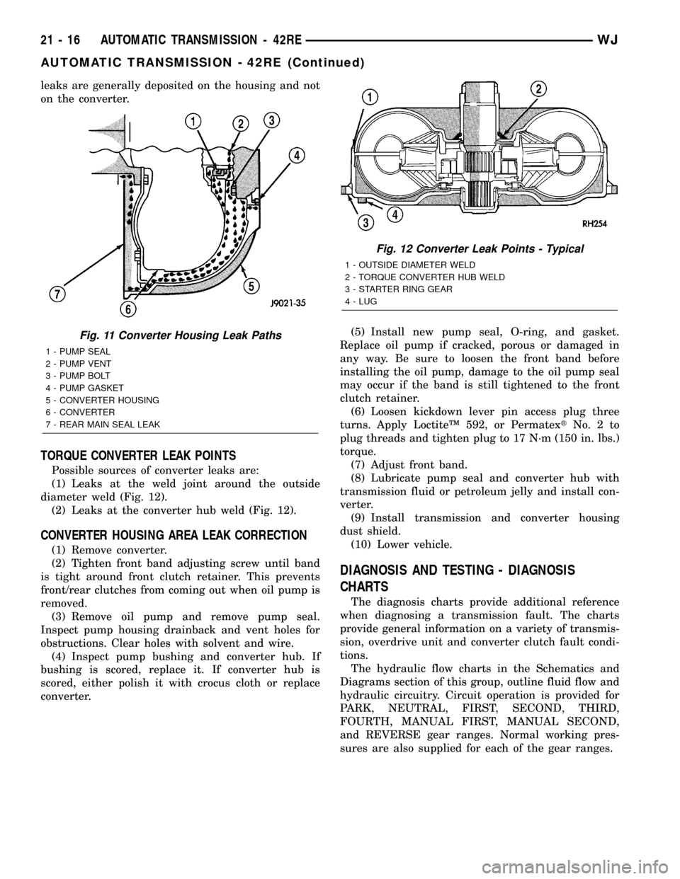
Possible sources of converter leaks are:
(1) Leaks at the weld joint around the outside
diameter weld (Fig. 12).
(2) Leaks at the converter hub weld (Fig. 12).
CONVERTER HOUSING AREA LEAK CORRECTION
(1) Remove converter.
(2) Tighten front band adjusting screw until band
is tight around front clutch retainer. This prevents
front/rear clutches from coming out when oil pump is
removed.
(3) Remove oil pump and remove pump seal.
Inspect pump housing drainback and vent holes for
obstructions. Clear holes with solvent and wire.
(4) Inspect pump bushing and converter hub. If
bushing is scored, replace it. If converter hub is
scored, either polish it with crocus cloth or replace
converter.(5) Install new pump seal, O-ring, and gasket.
Replace oil pump if cracked, porous or damaged in
any way. Be sure to loosen the front band before
installing the oil pump, damage to the oil pump seal
may occur if the band is still tightened to the front
clutch retainer.
(6) Loosen kickdown lever pin access plug three
turns. Apply LoctiteŸ 592, or PermatextNo.2to
plug threads and tighten plug to 17 N´m (150 in. lbs.)
torque.
(7) Adjust front band.
(8) Lubricate pump seal and converter hub with
transmission fluid or petroleum jelly and install con-
verter.
(9) Install transmission and converter housing
dust shield.
(10) Lower vehicle.
DIAGNOSIS AND TESTING - DIAGNOSIS
CHARTS
The diagnosis charts provide additional reference
when diagnosing a transmission fault. The charts
provide general information on a variety of transmis-
sion, overdrive unit and converter clutch fault condi-
tions.
The hydraulic flow charts in the Schematics and
Diagrams section of this group, outline fluid flow and
hydraulic circuitry. Circuit operation is provided for
PARK, NEUTRAL, FIRST, SECOND, THIRD,
FOURTH, MANUAL FIRST, MANUAL SECOND,
and REVERSE gear ranges. Normal working pres-
sures are also supplied for each of the gear ranges.
Fig. 11 Converter Housing Leak Paths
1 - PUMP SEAL
2 - PUMP VENT
3 - PUMP BOLT
4 - PUMP GASKET
5 - CONVERTER HOUSING
6 - CONVERTER
7 - REAR MAIN SEAL LEAK
Fig. 12 Converter Leak Points - Typical
1 - OUTSIDE DIAMETER WELD
2 - TORQUE CONVERTER HUB WELD
3 - STARTER RING GEAR
4 - LUG
21 - 16 AUTOMATIC TRANSMISSION - 42REWJ
AUTOMATIC TRANSMISSION - 42RE (Continued)