Fill JEEP GRAND CHEROKEE 2003 WJ / 2.G Workshop Manual
[x] Cancel search | Manufacturer: JEEP, Model Year: 2003, Model line: GRAND CHEROKEE, Model: JEEP GRAND CHEROKEE 2003 WJ / 2.GPages: 2199, PDF Size: 76.01 MB
Page 1985 of 2199
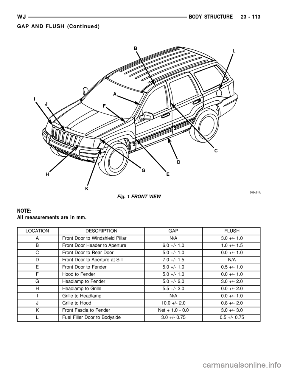
NOTE:
All measurements are in mm.
LOCATION DESCRIPTION GAP FLUSH
A Front Door to Windshield Pillar N/A 3.0 +/- 1.0
B Front Door Header to Aperture 6.0 +/- 1.0 1.0 +/- 1.5
C Front Door to Rear Door 5.0 +/- 1.0 0.0 +/- 1.0
D Front Door to Aperture at Sill 7.0 +/- 1.5 N/A
E Front Door to Fender 5.0 +/- 1.0 0.5 +/- 1.0
F Hood to Fender 5.0 +/- 1.0 0.0 +/- 1.0
G Headlamp to Fender 5.0 +/- 2.0 3.0 +/- 2.0
H Headlamp to Grille 5.5 +/- 2.0 0.0 +/- 2.0
I Grille to Headlamp N/A 0.0 +/- 1.0
J Grille to Hood 10.0 +/- 2.0 0.8 +/- 2.0
K Front Fascia to Fender Net + 1.0 - 0.0 3.0 +/- 3.0
L Fuel Filler Door to Bodyside 3.0 +/- 0.75 0.5 +/- 0.75
Fig. 1 FRONT VIEW
WJBODY STRUCTURE 23 - 113
GAP AND FLUSH (Continued)
Page 1991 of 2199
SEALER LOCATIONS
SPECIFICATIONS
SEALER LOCATIONS
INDEX
DESCRIPTION FIGURE
APPLICATION METHODS 6
COWL PLENUM AND DASH PANEL 7
DASH, COWL AND PLENUM 8
INNER FENDER AND COWL 9
LOWER PLENUM AND BAFFLE 10
A-PILLAR 11
COWL SIDE ATTACHMENT 12
BODYSIDE ATTACHMENT 13
BODYSIDE INNER AND OUTER TO COWL 14
FENDER ATTACHMENT 15
DOOR HINGE BOLT HOLES 16
A-PILLAR AND B-PILLAR HINGE AREA 17
B-PILLAR AND SILL 18
SILL AND B-PILLAR 19
BODYSIDE APERTURE AND REAR WHEELHOUSE 20
FUEL FILLER GUSSET 21
OUTER WHEELHOUSE FLANGE 22
LIFTGATE OPENING 23
INNER WHEELHOUSE FLANGE TO BODYSIDE APERTURE 24
WHEELHOUSE LOWER 25
REAR INNER CROSSMEMBER 26
ROOF TO BODY SIDE APERTURE 27
23 - 118 BODY STRUCTUREWJ
Page 2005 of 2199

Fig. 20 BODYSIDE APERTURE AND REAR WHEELHOUSE
Fig. 21 FUEL FILLER GUSSET
23 - 132 BODY STRUCTUREWJ
SEALER LOCATIONS (Continued)
Page 2010 of 2199
STUCTURAL ADHESIVE
LOCATIONS
SPECIFICATIONS - STRUCTURAL ADHESIVE
LOCATIONS
INDEX
DESCRIPTION FIGURE
COWL PLENUM 28
DASH PANEL AND FRONT FLOOR PAN 29
PLENUM AND WINDSHIELD WIPER MOUNTING 30
FRONT FLOOR PAN AND SILLS 31
FRONT AND CENTER FLOOR PAN 32
FRONT PAN AND INNER BODY SIDE APERTURE 33
REAR SEAT CROSSMEMBER 34
REAR INNER WHEELHOUSE 35
FLOOR PAN AND SILL ASSEMBLY 36
FLOOR PAN 37
REAR INNER WHEELHOUSE AND REAR FLOOR PAN 38
RIGHT INNER BODYSIDE APERTURE 39
BODY SIDE INNER PANEL AND WHEELHOUSE 40
BODY SIDE OUTER PANEL AND REAR WHEELHOUSE OUTER PANEL 41
D-PILLAR AND FUEL FILLER GUSSETS 42
LIFTGATE 43
TAILLAMP MOUNTING PANEL 44
TAILLAMP 45
REAR INNER CROSSMEMBER 46
ROOF BOWS 47
REAR LOWER HEADER 48
WJBODY STRUCTURE 23 - 137
Page 2020 of 2199

Fig. 42 D-PILLAR AND FUEL FILLER GUSSETS
WJBODY STRUCTURE 23 - 147
STUCTURAL ADHESIVE LOCATIONS (Continued)
Page 2027 of 2199
DESCRIPTION FIGURE
REINFORCEMENT FOR FRONT ENGINE MOUNTING AND STEERING GEAR TO
FRONT INNER SILL81
LARGE AND SMALL SWAY BAR TAPPING PLATES TO FRONT INNER SILLS 82
FRONT AND REAR DOOR HINGE TAPPING PLATES 83
REAR DOOR STRIKER REINFORCEMENT 84
TAIL LAMP MOUNTING PANELS 85
ROOF PANEL TO BODYSIDE APERTURE 86
ROOF PANEL TO REAR HEADER 87
UPPER REAR HEADER TO LOWER HEADER 88
FRONT HEADER AND ROOF BOWS TO INNER PANEL 89
FRONT SEAT/SHOULDER BELT TO INNER PANEL REINFORCEMENT 90
REAR SEAT/SHOULDER BELT TO INNER PANEL REINFORCEMENT 91
FUEL FILLER GUSSET TO INNER QUARTER PANEL 92
FRONT FLOOR PAN TO SILL REINFORCEMENT 93
CENTER FLOOR PAN TO REAR SEAT CROSSMEMBER 94
FRONT FLOOR PAN TO FRONT SEAT REINFORCEMENT AND RAILS 95
CENTER FLOOR PAN TO UPPER CONTROL ARM CROSSMEMBER AND RAILS 96
REAR FLOOR PAN TO RAILS AND SPRING GUIDE CROSSMEMBER 97
REAR RAILS 98
UPPER CONTROL ARM CROSSMEMBER TO REAR RAIL 99
REAR RAIL REINFORCEMENT TO REAR RAILS 100
UPPER CONTROL ARM REINFORCEMENTS TO REAR RAIL 101
OUTER TRANSMISSION CROSSMEMBER REINFORCEMENT TO RAIL AND
BODYSIDE SILL102
BODYSIDE SILL TO FLOOR PAN 103
REAR RAILS TO REAR CROSSMEMBER 104
INNER WHEELHOUSE TO FLOOR PAN 105
INNER WHEELHOUSE TO INNER BODYSIDE APERTURE AND FLOOR PAN 106
OUTER WHEELHOUSE TO OUTER BODYSIDE APERTURE 107
OUTER WHEELHOUSE TO INNER BODYSIDE APERTURE 108
INNER BODYSIDE APERTURE TO OUTER BODYSIDE APERTURE 109
REAR INBOARD SEAT BELT REINFORCEMENT TO FLOOR PAN 110
23 - 154 BODY STRUCTUREWJ
WELD LOCATIONS (Continued)
Page 2063 of 2199

Fig. 91 REAR SEAT/SHOULDER BELT TO INNER PANEL REINFORCEMENT
Fig. 92 FUEL FILLER GUSSET TO INNER QUARTER PANEL
23 - 190 BODY STRUCTUREWJ
WELD LOCATIONS (Continued)
Page 2122 of 2199

NOTE: The blend door sub-assembly is attached to
the housing with 2 screws, and may be removed for
service (Fig. 19).
ASSEMBLY
(1) Place the top half of the HVAC housing on the
bottom half. Be certain that each of the door pivot
pins align with the pivot holes in the HVAC housing.
(2) Install the 10 screws that secure the two hous-
ing halves to each other. Tighten the HVAC housing
screws to 2.2 N´m (20 in. lbs.).
(3) Attach the wire harness electrical connector(s)
to the mounts on the lower case at the blower motor
end of the unit.
(4) Install the 5 clips that secure the two housing
halves to each other. Check doors for binding after
replacement, and after assembly of housing.
(5) Install the screw with plastic washer holding
the lever assembly to the upper case section.
(6) Install the mode door actuator on the left side
of the housing.
INSTALLATION
WARNING: REVIEW THE WARNINGS AND CAU-
TIONS IN PLUMBING BEFORE PERFORMING THE
FOLLOWING OPERATION. (Refer to 24 - HEATING &
AIR CONDITIONING/PLUMBING - WARNING) (Refer
to 24 - HEATING & AIR CONDITIONING/PLUMBING -
CAUTION)Any kinks or sharp bends in the refrigerant plumb-
ing will reduce the capacity of the entire air condi-
tioning system. Kinks and sharp bends reduce the
flow of refrigerant in the system. A good rule for the
flexible hose refrigerant lines is to keep the radius of
all bends at least ten times the diameter of the hose.
In addition, the flexible hose refrigerant lines should
be routed so they are at least 80 millimeters (3
inches) from the exhaust manifold.
High pressures are produced in the refrigerant sys-
tem when the air conditioning compressor is operat-
ing. Extreme care must be exercised to make sure
that each of the refrigerant system connections is
pressure-tight and leak free. It is a good practice to
inspect all flexible hose refrigerant lines at least once
a year to make sure they are in good condition and
properly routed.
(1) Position the HVAC housing to the dash panel.
Be certain that the evaporator condensate drain tube
and the housing mounting studs are inserted into
their correct mounting holes.
(2) Install the HVAC housing mounting nuts to the
studs on the passenger compartment side of the dash
panel. Tighten the nuts to 4.5 N´m (40 in. lbs.).
(3) Connect the HVAC housing wire harness con-
nectors.
(4) Reinstall the rear floor heat ducts to the center
floor heat duct outlets.
(5) Install and tighten the nuts onto the HVAC
housing mounting studs on the engine compartment
side of the dash panel. Tighten the nuts to 7 N´m (60
in. lbs.).
(6) Reinstall the PCM to the passenger side dash
panel in the engine compartment. Refer to Electronic
Control Modules for the procedures.
(7) Reinstall the coolant reserve/overflow bottle to
the passenger side inner fender shield. Refer to Cool-
ing for the procedures.
(8) If the vehicle is equipped with the manual tem-
perature control system, connect the HVAC system
vacuum supply line connector to the tee fitting near
the heater core tubes.
(9) Unclamp/unplug the heater core hoses and
tubes. Connect the heater hoses to the heater core
tubes and fill the engine cooling system. Refer to
Cooling for the procedures.
(10) Unplug or remove the tape from the suction
line and the evaporator outlet tube fittings. Connect
the suction line to the evaporator outlet tube.
Tighten retaining nut to 28 N´m (250 in. lbs.).
(11) Unplug or remove the tape from the liquid
line and the evaporator inlet tube fittings. Connect
the liquid line to the evaporator inlet tube. Tighten
retaining nut to 28 N´m (250 in. lbs.).
(12) Evacuate the refrigerant system. (Refer to 24
- HEATING & AIR CONDITIONING/PLUMBING -
Fig. 19 BLEND DOOR SUB-ASSEMBLY (AZC)
1 - PASSENGER SIDE BLEND DOOR
2 - BLEND DOOR SUB-ASSEMBLY
3 - DOOR PIVOT SHAFT BUSHING
4 - DOOR SHAFT LEVER
5 - DRIVER SIDE BLEND DOOR
WJDISTRIBUTION 24 - 45
HVAC HOUSING (Continued)
Page 2152 of 2199
REFRIGERANT
DESCRIPTION
The refrigerant used in this air conditioning sys-
tem is a HydroFluoroCarbon (HFC), type R-134a.
Unlike R-12, which is a ChloroFluoroCarbon (CFC),
R-134a refrigerant does not contain ozone-depleting
chlorine. R-134a refrigerant is a non-toxic, non-flam-
mable, clear, and colorless liquefied gas.
Even though R-134a does not contain chlorine, it
must be reclaimed and recycled just like CFC-type
refrigerants. This is because R-134a is a greenhouse
gas and can contribute to global warming.
OPERATION
R-134a refrigerant is not compatible with R-12
refrigerant in an air conditioning system. Even a
small amount of R-12 added to an R-134a refrigerant
system will cause compressor failure, refrigerant oil
sludge or poor air conditioning system performance.
In addition, the PolyAlkylene Glycol (PAG) synthetic
refrigerant oils used in an R-134a refrigerant system
are not compatible with the mineral-based refriger-
ant oils used in an R-12 refrigerant system.
R-134a refrigerant system service ports, service
tool couplers and refrigerant dispensing bottles have
all been designed with unique fittings to ensure that
an R-134a system is not accidentally contaminated
with the wrong refrigerant (R-12). There are also
labels posted in the engine compartment of the vehi-
cle and on the compressor identifying to service tech-
nicians that the air conditioning system is equipped
with R-134a.
REFRIGERANT OIL
DESCRIPTION
The refrigerant oil used in R-134a refrigerant sys-
tems is a synthetic-based, PolyAlkylene Glycol (PAG),
wax-free lubricant. Mineral-based R-12 refrigerant
oils are not compatible with PAG oils, and should
never be introduced to an R-134a refrigerant system.
There are different PAG oils available, and each
contains a different additive package. The 10PA17
compressor used in this vehicle is designed to use an
ND8 PAG refrigerant oil. Use only refrigerant oil of
this same type to service the refrigerant system.
OPERATION
After performing any refrigerant recovery or recy-
cling operation, always replenish the refrigerant sys-
tem with the same amount of the recommended
refrigerant oil as was removed. Too little refrigerant
oil can cause compressor damage, and too much can
reduce air conditioning system performance.PAG refrigerant oil is much more hygroscopic than
mineral oil, and will absorb any moisture it comes
into contact with, even moisture in the air. The PAG
oil container should always be kept tightly capped
until it is ready to be used. After use, recap the oil
container immediately to prevent moisture contami-
nation.
STANDARD PROCEDURE - REFRIGERANT OIL
LEVEL
When an air conditioning system is assembled at
the factory, all components except the compressor are
refrigerant oil free. After the refrigerant system has
been charged and operated, the refrigerant oil in the
compressor is dispersed throughout the refrigerant
system. The accumulator, evaporator, condenser, and
compressor will each retain a significant amount of
the needed refrigerant oil.
It is important to have the correct amount of oil in
the refrigerant system. This ensures proper lubrica-
tion of the compressor. Too little oil will result in
damage to the compressor. Too much oil will reduce
the cooling capacity of the air conditioning system.
It will not be necessary to check the oil level in the
compressor or to add oil, unless there has been an oil
loss. An oil loss may occur due to a rupture or leak
from a refrigerant line, a connector fitting, a compo-
nent, or a component seal. If a leak occurs, add 30
milliliters (1 fluid ounce) of refrigerant oil to the
refrigerant system after the repair has been made.
Refrigerant oil loss will be evident at the leak point
by the presence of a wet, shiny surface around the
leak.
Refrigerant oil must be added when a accumulator,
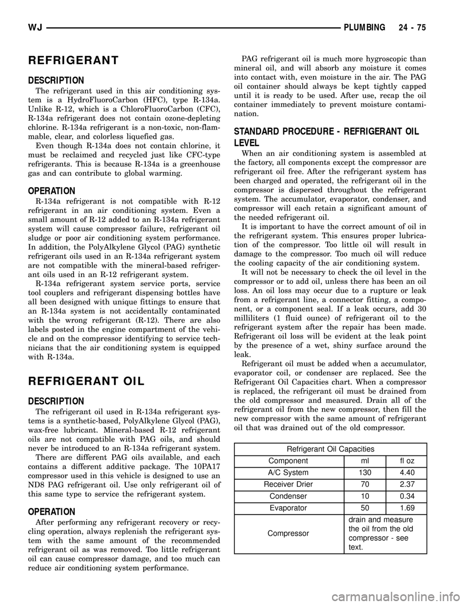
evaporator coil, or condenser are replaced. See the
Refrigerant Oil Capacities chart. When a compressor
is replaced, the refrigerant oil must be drained from
the old compressor and measured. Drain all of the
refrigerant oil from the new compressor, then fill the
new compressor with the same amount of refrigerant
oil that was drained out of the old compressor.
Refrigerant Oil Capacities
Component ml fl oz
A/C System 130 4.40
Receiver Drier 70 2.37
Condenser 10 0.34
Evaporator 50 1.69
Compressordrain and measure
the oil from the old
compressor - see
text.
WJPLUMBING 24 - 75
Page 2155 of 2199

(14) Remove the snap ring from the hub and
remove the clutch field coil (Fig. 22). Slide the clutch
field coil off of the hub.
INSTALLATION
INSTALLATION
(1) Install Viscous Heater to engine mounting
bracket.
(2) Install the Viscous Heater mounting bolts and
tighten to 33 N´m ( 25 ft. lbs.).
(3) Plug the wiring harness electrical connector to
the Viscous Heater clutch.
(4) Install heater hoses to the Viscous Heater con-
nections.
(5) Install heater hose clamps to Viscous Heater
connections.
(6) Install the engine accessory drive belt(Refer to
7 - COOLING/ACCESSORY DRIVE/DRIVE BELTS -
INSTALLATION).
(7) Refill the engine cooling system(Refer to 7 -
COOLING/ENGINE - STANDARD PROCEDURE).
(8) Reconnect the battery negative cable.
(9) Operate vehicle and check for any coolant
leaks, repair as required.
INSTALLATION - VISCOUS HEATER CLUTCH
(1) Install the clutch field coil and snap ring.
(2) Install the screw and retainer on the clutch coil
lead wire harness on the viscous heater housing.
Tighten the screw to 2.2 N´m (20 in. lbs.)
(3) Align the rotor assembly squarely on the front
housing hub.
(4) Install the rotor bearing asembly with the
installer (Special Tool C-6871 or equalivent). Threadthe installer on the shaft, then turn the nut until the
rotor asembly is seated.
(5) Install the external front housing snap ring
with snap ring pliers. The bevel side of the snap ring
must be facing outward. Press the snap ring to make
sure it is properly seated in the groove.
CAUTION: If the snap ring is not fully seated in the
groove it will vibrate out, resulting in a clutch fail-
ure and severe damage to the front housing of the
compressor.
(6) Install the original clutch shims on the shaft.
(7) Install the clutch plate. Install the shaft hex
nut and tighten to 15±20 N´m (11±15 ft. lbs.).
(8) Check the clutch air gap with a feeler gauge
(Fig. 23). If the gap does not meet specification, add
or substract shims as required. The air gap specifica-
tion if 0.41 to 0.79 millimeters (0.016 to 0.031 inch-
es).
NOTE: The air gap is determined by the spacer
shims. When installing an original, or a new clutch
assembly, try the original shims first. When install-
ing a new clutch (and not having the old shims
available) use a 1.0, 0.50 and 0.13 millimeter (0.040,
0.020 and 0.005 inch) shim from the new clutch
hardware package that is provided with the new
clutch.
(9) Reinstall the viscous heater to the mounting
bracket. Tighten the mounting screws to 33 N´m (25
ft. lbs.).
(10) Reinstall the battery negative cable.
Fig. 22 CLUTCH FIELD COIL SNAP RING REMOVE-
typical
1 - COIL
2 - SNAP RING PLIERS
Fig. 23 CHECK CLUTCH AIR GAP-typical
1 - FEELER GAUGE
24 - 78 PLUMBINGWJ
VISCOUS HEATER (Continued)