Accessories JEEP GRAND CHEROKEE 2003 WJ / 2.G User Guide
[x] Cancel search | Manufacturer: JEEP, Model Year: 2003, Model line: GRAND CHEROKEE, Model: JEEP GRAND CHEROKEE 2003 WJ / 2.GPages: 2199, PDF Size: 76.01 MB
Page 349 of 2199

The battery cables (Fig. 17) or (Fig. 18) are large
gauge, stranded copper wires sheathed within a
heavy plastic or synthetic rubber insulating jacket.
The wire used in the battery cables combines excel-
lent flexibility and reliability with high electrical cur-
rent carrying capacity. Refer toWiring Diagrams
for battery cable wire gauge information.
A clamping type female battery terminal made of
soft lead is die cast onto one end of the battery cable
wire. A square headed pinch-bolt and hex nut are
installed at the open end of the female battery termi-
nal clamp. Large eyelet type terminals are crimped
onto the opposite end of the battery cable wire and
then solder-dipped. The battery positive cable wires
have a red insulating jacket to provide visual identi-
fication and feature a larger female battery terminal
clamp to allow connection to the larger battery posi-
tive terminal post. The battery negative cable wires
have a black insulating jacket and a smaller female
battery terminal clamp.
The battery cables cannot be repaired and, if dam-
aged or faulty they must be replaced. Both the bat-
tery positive and negative cables are available for
service replacement only as a unit with the battery
wire harness, which may include portions of the wir-
ing circuits for the generator and other components
on some models. Refer toWiring Diagramsfor more
information on the various wiring circuits included in
the battery wire harness for the vehicle being ser-
viced.
OPERATION
The battery cables connect the battery terminal
posts to the vehicle electrical system. These cables
also provide a path back to the battery for electrical
current generated by the charging system for restor-
ing the voltage potential of the battery. The female
battery terminal clamps on the ends of the battery
cable wires provide a strong and reliable connection
of the battery cable to the battery terminal posts.
The terminal pinch bolts allow the female terminal
clamps to be tightened around the male terminal
posts on the top of the battery. The eyelet terminals
secured to the opposite ends of the battery cable
wires from the female battery terminal clamps pro-
vide secure and reliable connection of the battery
cables to the vehicle electrical system.
The battery positive cable terminal clamp is die
cast onto the ends of two wires. One wire has an eye-
let terminal that connects the battery positive cable
to the B(+) terminal stud of the Power Distribution
Center (PDC), and the other wire has an eyelet ter-
minal that connects the battery positive cable to the
B(+) terminal stud of the engine starter motor sole-
noid. The battery negative cable terminal clamp is
also die cast onto the ends of two wires. One wirehas an eyelet terminal that connects the battery neg-
ative cable to the vehicle powertrain through a stud
on the right side of the engine cylinder block. The
other wire has an eyelet terminal that connects the
battery negative cable to the vehicle body through a
ground screw on the right front fender inner shield,
near the battery.
DIAGNOSIS AND TESTING - BATTERY CABLES
A voltage drop test will determine if there is exces-
sive resistance in the battery cable terminal connec-
tions or the battery cable. If excessive resistance is
found in the battery cable connections, the connec-
tion point should be disassembled, cleaned of all cor-
rosion or foreign material, then reassembled.
Following reassembly, check the voltage drop for the
battery cable connection and the battery cable again
to confirm repair.
When performing the voltage drop test, it is impor-
tant to remember that the voltage drop is giving an
indication of the resistance between the two points at
which the voltmeter probes are attached.EXAM-
PLE:When testing the resistance of the battery pos-
itive cable, touch the voltmeter leads to the battery
positive cable terminal clamp and to the battery pos-
itive cable eyelet terminal at the starter solenoid
B(+) terminal stud. If you probe the battery positive
terminal post and the battery positive cable eyelet
terminal at the starter solenoid B(+) terminal stud,
you are reading the combined voltage drop in the
battery positive cable terminal clamp-to-terminal
post connection and the battery positive cable.
VOLTAGE DROP TEST
The following operation will require a voltmeter
accurate to 1/10 (0.10) volt. Before performing this
test, be certain that the following procedures are
accomplished:
²The battery is fully-charged and load tested.
Refer to Standard Procedures for the proper battery
charging and load test procedures.
²Fully engage the parking brake.
²If the vehicle is equipped with an automatic
transmission, place the gearshift selector lever in the
Park position. If the vehicle is equipped with a man-
ual transmission, place the gearshift selector lever in
the Neutral position and block the clutch pedal in the
fully depressed position.
²Verify that all lamps and accessories are turned
off.
²To prevent the engine from starting, remove the
Automatic Shut Down (ASD) relay. The ASD relay is
located in the Power Distribution Center (PDC), in
the engine compartment. See the fuse and relay lay-
out label affixed to the underside of the PDC cover
for ASD relay identification and location.
8F - 18 BATTERY SYSTEMWJ
BATTERY CABLE (Continued)
Page 350 of 2199

(1) Connect the positive lead of the voltmeter to
the battery negative terminal post. Connect the neg-
ative lead of the voltmeter to the battery negative
cable terminal clamp (Fig. 19). Rotate and hold the
ignition switch in the Start position. Observe the
voltmeter. If voltage is detected, correct the poor con-
nection between the battery negative cable terminal
clamp and the battery negative terminal post.
(2) Connect the positive lead of the voltmeter to
the battery positive terminal post. Connect the nega-
tive lead of the voltmeter to the battery positive cable
terminal clamp (Fig. 20). Rotate and hold the ignition
switch in the Start position. Observe the voltmeter. If
voltage is detected, correct the poor connection
between the battery positive cable terminal clamp
and the battery positive terminal post.
(3) Connect the voltmeter to measure between the
battery positive cable terminal clamp and the starter
solenoid B(+) terminal stud (Fig. 21). Rotate and hold
the ignition switch in the Start position. Observe the
voltmeter. If the reading is above 0.2 volt, clean and
tighten the battery positive cable eyelet terminal con-
nection at the starter solenoid B(+) terminal stud.
Repeat the test. If the reading is still above 0.2 volt,
replace the faulty battery positive cable.
(4) Connect the voltmeter to measure between the
battery negative cable terminal clamp and a good
clean ground on the engine block (Fig. 22). Rotate
and hold the ignition switch in the Start position.
Observe the voltmeter. If the reading is above 0.2
volt, clean and tighten the battery negative cable
eyelet terminal connection to the engine block.
Repeat the test. If the reading is still above 0.2 volt,
replace the faulty battery negative cable.
REMOVAL
Both the battery negative cable and the battery
positive cable are serviced in the battery wire har-
ness. If either battery cable is damaged or faulty, the
battery wire harness unit must be replaced.
(1) Turn the ignition switch to the Off position. Be
certain that all electrical accessories are turned off.
(2) Loosen the battery negative cable terminal
clamp pinch-bolt hex nut.
(3) Disconnect the battery negative cable terminal
clamp from the battery negative terminal post. If
necessary, use a battery terminal puller to remove
the terminal clamp from the battery post.
Fig. 19 TEST BATTERY NEGATIVE CONNECTION
RESISTANCE - TYPICAL
1 - VOLTMETER
2 - BATTERY
Fig. 20 TEST BATTERY POSITIVE CONNECTION
RESISTANCE - TYPICAL
1 - VOLTMETER
2 - BATTERY
Fig. 21 TEST BATTERY POSITIVE CABLE
RESISTANCE - TYPICAL
1 - BATTERY
2 - VOLTMETER
3 - STARTER MOTOR
WJBATTERY SYSTEM 8F - 19
BATTERY CABLE (Continued)
Page 355 of 2199

CHARGING
TABLE OF CONTENTS
page page
CHARGING
DESCRIPTION.........................24
OPERATION...........................24
DIAGNOSIS AND TESTING - CHARGING
SYSTEM............................24
SPECIFICATIONS
GENERATOR RATINGS - GAS POWERED . . 25
TORQUE - GAS POWERED.............25
SPECIAL TOOLS.......................26
BATTERY TEMPERATURE SENSOR
DESCRIPTION.........................26OPERATION...........................26
REMOVAL.............................26
INSTALLATION.........................26
GENERATOR
DESCRIPTION.........................27
OPERATION...........................27
REMOVAL.............................27
INSTALLATION.........................28
VOLTAGE REGULATOR
DESCRIPTION.........................28
OPERATION...........................28
CHARGING
DESCRIPTION
The charging system consists of:
²Generator
²Electronic Voltage Regulator (EVR) circuitry
within the Powertrain Control Module (PCM)
²Ignition switch
²Battery (refer to 8, Battery for information)
²Battery temperature sensor
²Generator Lamp (if equipped)
²Check Gauges Lamp (if equipped)
²Voltmeter (refer to 8, Instrument Cluster for
information)
²Wiring harness and connections (refer to 8, Wir-
ing for information)
OPERATION
The charging system is turned on and off with the
ignition switch. The system is on when the engine is
running and the ASD relay is energized. When the
ASD relay is on, voltage is supplied to the ASD relay
sense circuit at the PCM. This voltage is connected
through the PCM and supplied to one of the genera-
tor field terminals (Gen. Source +) at the back of the
generator.
The amount of DC current produced by the gener-
ator is controlled by the EVR (field control) circuitry
contained within the PCM. This circuitry is con-
nected in series with the second rotor field terminal
and ground.
A battery temperature sensor, located in the bat-
tery tray housing, is used to sense battery tempera-
ture. This temperature data, along with data from
monitored line voltage, is used by the PCM to vary
the battery charging rate. This is done by cycling theground path to control the strength of the rotor mag-
netic field. The PCM then compensates and regulates
generator current output accordingly.
All vehicles are equipped with On-Board Diagnos-
tics (OBD). All OBD-sensed systems, including EVR
(field control) circuitry, are monitored by the PCM.
Each monitored circuit is assigned a Diagnostic Trou-
ble Code (DTC). The PCM will store a DTC in elec-
tronic memory for certain failures it detects. Refer to
Diagnostic Trouble Codes in; Powertrain Control
Module; Electronic Control Modules for more DTC
information.
The Check Gauges Lamp (if equipped) monitors:
charging system voltage,engine coolant tempera-
ture and engine oil pressure. If an extreme condition
is indicated, the lamp will be illuminated. This is
done as reminder to check the three gauges. The sig-
nal to activate the lamp is sent via the CCD bus cir-
cuits. The lamp is located on the instrument panel.
Refer to 8, Instrument Cluster for additional infor-
mation.
DIAGNOSIS AND TESTING - CHARGING
SYSTEM
The following procedures may be used to diagnose
the charging system if:
²the check gauges lamp (if equipped) is illumi-
nated with the engine running
²the voltmeter (if equipped) does not register
properly
²an undercharged or overcharged battery condi-
tion occurs.
Remember that an undercharged battery is often
caused by:
²accessories being left on with the engine not
running
8F - 24 CHARGINGWJ
Page 363 of 2199

INSPECTION
For complete circuit diagrams, refer toStarting
Systemin the Contents of Group 8W - Wiring Dia-
grams. Before removing any unit from the starting
system for repair or diagnosis, perform the following
inspections:
WARNING: ON VEHICLES EQUIPPED WITH AIR-
BAGS, REFER TO GROUP 8M - PASSIVE
RESTRAINT SYSTEMS BEFORE ATTEMPTING ANY
STEERING WHEEL, STEERING COLUMN, OR
INSTRUMENT PANEL COMPONENT DIAGNOSIS OR
SERVICE. FAILURE TO TAKE THE PROPER PRE-
CAUTIONS COULD RESULT IN ACCIDENTAL AIR-
BAG DEPLOYMENT AND POSSIBLE PERSONAL
INJURY.
²Battery- Visually inspect the battery for indi-
cations of physical damage and loose or corroded
cable connections. Determine the state-of-charge and
cranking capacity of the battery. Charge or replace
the battery, if required. Refer toBatteryin the
proper section of Group 8A - Battery for complete ser-
vice information for the battery.
²Ignition Switch- Visually inspect the ignition
switch for indications of physical damage and loose
or corroded wire harness connections. Refer toIgni-
tion Switch and Key Lock Cylinderin the proper
section of Group 8D - Ignition System for complete
service information for the ignition switch.
²Park/Neutral Position Switch- Visually
inspect the park/neutral position switch for indica-
tions of physical damage and loose or corroded wire
harness connections. Refer toPark/Neutral Posi-
tion Switchin the proper section of Group 21 -
Transmission for complete service information for the
park/neutral position switch.
²Starter Relay- Visually inspect the starter
relay for indications of physical damage and loose or
corroded wire harness connections.
²Starter Motor- Visually inspect the starter
motor for indications of physical damage and loose or
corroded wire harness connections.
²Starter Solenoid- Visually inspect the starter
solenoid for indications of physical damage and loose
or corroded wire harness connections.
²Wiring- Visually inspect the wire harnesses for
damage. Repair or replace any faulty wiring, as
required. Refer to the proper section ofGroup 8W -
Wiring Diagramsfor complete service information
and circuit diagrams for the starting system wiring
components.TESTING
COLD CRANKING TEST
For complete circuit diagrams, refer toStarting
Systemin the Contents of Group 8W - Wiring Dia-
grams. The battery must be fully-charged and load-
tested before proceeding. Refer toBatteryin the
Diagnosis and Testing section of Group 8A - Battery
for the procedures.
(1) Connect a suitable volt-ampere tester to the
battery terminals (Fig. 1). See the instructions pro-
vided by the manufacturer of the volt-ampere tester
being used.
(2) Fully engage the parking brake.
(3) Place the automatic transmission gearshift
selector lever in the Park position.
(4) Verify that all lamps and accessories are
turned off.
(5) To prevent the engine from starting, remove
the Automatic ShutDown (ASD) relay. The ASD relay
is located in the Power Distribution Center (PDC), in
the engine compartment. Refer to the fuse and relay
layout label affixed to the underside of the PDC cover
for ASD relay identification and location.
(6) Rotate and hold the ignition switch in the Start
position. Note the cranking voltage and current
(amperage) draw readings shown on the volt-ampere
tester.
(a) If the voltage reads below 9.6 volts, refer to
Starter Motorin the Diagnosis and Testing sec-
tion of this group. If the starter motor is OK, refer
toEngine Diagnosisin the Diagnosis and Testing
section of Group 9 - Engine for further testing of
the engine. If the starter motor is not OK, replace
the faulty starter motor.
Fig. 1 Volts-Amps Tester Connections - Typical
1 - POSITIVE CLAMP
2 - NEGATIVE CLAMP
3 - INDUCTION AMMETER CLAMP
8F - 32 STARTINGWJ
STARTING (Continued)
Page 364 of 2199

(b) If the voltage reads above 9.6 volts and the
current (amperage) draw reads below specifica-
tions, refer toFeed Circuit Testin this section.
(c) If the voltage reads 12.5 volts or greater and
the starter motor does not turn, refer toControl
Circuit Testingin this section.
(d) If the voltage reads 12.5 volts or greater and
the starter motor turns very slowly, refer toFeed
Circuit Testin this section.
NOTE: A cold engine will increase the starter cur-
rent (amperage) draw reading, and reduce the bat-
tery voltage reading.
FEED CIRCUIT TEST
The starter feed circuit test (voltage drop method)
will determine if there is excessive resistance in the
high-amperage feed circuit. For complete circuit dia-
grams, refer toStarting Systemin the Contents of
Group 8W - Wiring Diagrams.
When performing these tests, it is important to
remember that the voltage drop is giving an indica-
tion of the resistance between the two points at
which the voltmeter probes are attached.
Example:When testing the resistance of the bat-
tery positive cable, touch the voltmeter leads to the
battery positive cable clamp and the cable connector
at the starter solenoid. If you probe the battery pos-
itive terminal post and the cable connector at the
starter solenoid, you are reading the combined volt-
age drop in the battery positive cable clamp-to-termi-
nal post connection and the battery positive cable.
The following operation will require a voltmeter
accurate to 1/10 (0.10) volt. Before performing the
tests, be certain that the following procedures are
accomplished:
²Battery is fully-charged and load-tested. Refer to
Batteryin the Diagnosis and Testing section of
Group 8A - Battery for the procedures.
²Fully engage the parking brake.
²Place the automatic transmission gearshift selec-
tor lever in the Park position.
²
Verify that all lamps and accessories are turned off.
²To prevent the engine from starting, remove the
Automatic ShutDown (ASD) relay. The ASD relay is
located in the Power Distribution Center (PDC), in
the engine compartment. Refer to the fuse and relay
layout label affixed to the underside of the PDC cover
for ASD relay identification and location.
(1) Connect the positive lead of the voltmeter to
the battery negative terminal post. Connect the neg-
ative lead of the voltmeter to the battery negative
cable clamp (Fig. 2). Rotate and hold the ignition
switch in the Start position. Observe the voltmeter. If
voltage is detected, correct the poor contact between
the cable clamp and the terminal post.(2) Connect the positive lead of the voltmeter to
the battery positive terminal post. Connect the nega-
tive lead of the voltmeter to the battery positive cable
clamp (Fig. 3). Rotate and hold the ignition switch in
the Start position. Observe the voltmeter. If voltage
is detected, correct the poor contact between the
cable clamp and the terminal post.
(3) Connect the voltmeter to measure between the
battery positive terminal post and the starter sole-
noid battery terminal stud (Fig. 4). Rotate and hold
the ignition switch in the Start position. Observe the
voltmeter. If the reading is above 0.2 volt, clean and
tighten the battery cable connection at the solenoid.
Fig. 2 Test Battery Negative Connection Resistance
- Typical
1 - VOLTMETER
2 - BATTERY
Fig. 3 Test Battery Positive Connection Resistance -
Typical
1 - VOLTMETER
2 - BATTERY
WJSTARTING 8F - 33
STARTING (Continued)
Page 661 of 2199
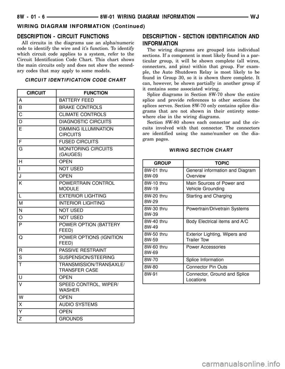
DESCRIPTION - CIRCUIT FUNCTIONS
All circuits in the diagrams use an alpha/numeric
code to identify the wire and it's function. To identify
which circuit code applies to a system, refer to the
Circuit Identification Code Chart. This chart shows
the main circuits only and does not show the second-
ary codes that may apply to some models.
CIRCUIT IDENTIFICATION CODE CHART
CIRCUIT FUNCTION
A BATTERY FEED
B BRAKE CONTROLS
C CLIMATE CONTROLS
D DIAGNOSTIC CIRCUITS
E DIMMING ILLUMINATION
CIRCUITS
F FUSED CIRCUITS
G MONITORING CIRCUITS
(GAUGES)
H OPEN
I NOT USED
J OPEN
K POWERTRAIN CONTROL
MODULE
L EXTERIOR LIGHTING
M INTERIOR LIGHTING
N NOT USED
O NOT USED
P POWER OPTION (BATTERY
FEED)
Q POWER OPTIONS (IGNITION
FEED)
R PASSIVE RESTRAINT
S SUSPENSION/STEERING
T TRANSMISSION/TRANSAXLE/
TRANSFER CASE
U OPEN
V SPEED CONTROL, WIPER/
WASHER
W OPEN
X AUDIO SYSTEMS
Y OPEN
Z GROUNDS
DESCRIPTION - SECTION IDENTIFICATION AND
INFORMATION
The wiring diagrams are grouped into individual
sections. If a component is most likely found in a par-
ticular group, it will be shown complete (all wires,
connectors, and pins) within that group. For exam-
ple, the Auto Shutdown Relay is most likely to be
found in Group 30, so it is shown there complete. It
can, however, be shown partially in another group if
it contains some associated wiring.
Splice diagrams in Section 8W-70 show the entire
splice and provide references to other sections the
splices serves. Section 8W-70 only contains splice dia-
grams that are not shown in their entirety some-
where else in the wiring diagrams.
Section 8W-80 shows each connector and the cir-
cuits involved with that connector. The connectors
are identified using the name/number on the dia-
gram pages.
WIRING SECTION CHART
GROUP TOPIC
8W-01 thru
8W-09General information and Diagram
Overview
8W-10 thru
8W-19Main Sources of Power and
Vehicle Grounding
8W-20 thru
8W-29Starting and Charging
8W-30 thru
8W-39Powertrain/Drivetrain Systems
8W-40 thru
8W-49Body Electrical items and A/C
8W-50 thru
8W-59Exterior Lighting, Wipers and
Trailer Tow
8W-60 thru
8W-69Power Accessories
8W-70 Splice Information
8W-80 Connector Pin Outs
8W-91 Connector, Ground and Splice
Locations
8W - 01 - 6 8W-01 WIRING DIAGRAM INFORMATIONWJ
WIRING DIAGRAM INFORMATION (Continued)
Page 1227 of 2199

the same time, the power distribution system was
designed to provide ready access to these electrical
distribution points for the vehicle technician to use
when conducting diagnosis and repair of faulty cir-
cuits. The power distribution system can also prove
useful for the sourcing of additional electrical circuits
that may be required to provide the electrical current
needed to operate accessories that the vehicle owner
may choose to have installed in the aftermarket.
NOTE: DO NOT ATTEMPT TO SWAP POWER DIS-
TRIBUTION CENTERS FROM ONE VEHICLE TO
ANOTHER. MOST OF THESE ASSEMBLIES ARE
VEHICLE FEATURE SPECIFIC AND THEREFORE
NOT INTERCHANGEABLE. ALWAYS USE THE COR-
RECT PART NUMBERED ASSEMBLY WHEN DIAG-
NOSING OR REPLACING A POWER DISTRIBUTION
CENTER.
SPECIAL TOOLS
POWER DISTRIBUTION SYSTEMS
CIGAR LIGHTER OUTLET
DESCRIPTION
A cigar lighter outlet is standard equipment on
this model. On models equipped with the optional
Smoker's Package, the cigar lighter knob and heating
element are included. On models without the Smok-
er's Package, the cigar lighter outlet is equipped with
a snap fit plastic cap and is treated as an extra
accessory power outlet. The cigar lighter outlet is
installed in the instrument panel center lower bezel,
which is located near the bottom of the instrument
panel center stack area, below the heater and air
conditioner controls. The cigar lighter outlet is
secured by a snap fit within the center lower bezel.The cigar lighter outlet, plastic cap and the knob
and heating element unit are available for service
replacement. These components cannot be repaired
and, if faulty or damaged, they must be replaced.
OPERATION
The cigar lighter consists of two major components:
a knob and heating element unit, and the cigar
lighter base or outlet shell. The receptacle shell is
connected to ground, and an insulated contact in the
bottom of the shell is connected to battery current.
The cigar lighter receives battery voltage from a fuse
in the junction block when the ignition switch is in
the Accessory or On positions.
The cigar lighter knob and heating element are
encased within a spring-loaded housing, which also
features a sliding protective heat shield. When the
knob and heating element are inserted in the outlet
shell, the heating element resistor coil is grounded
through its housing to the outlet shell. If the cigar
lighter knob is pushed inward, the heat shield slides
up toward the knob exposing the heating element,
and the heating element extends from the housing
toward the insulated contact in the bottom of the
outlet shell.
Two small spring-clip retainers are located on
either side of the insulated contact inside the bottom
of the outlet shell. These clips engage and hold the
heating element against the insulated contact long
enough for the resistor coil to heat up. When the
heating element is engaged with the contact, battery
current can flow through the resistor coil to ground,
causing the resistor coil to heat.
When the resistor coil becomes sufficiently heated,
excess heat radiates from the heating element caus-
ing the spring-clips to expand. Once the spring-clips
expand far enough to release the heating element,
the spring-loaded housing forces the knob and heat-
ing element to pop back outward to their relaxed
position. When the cigar lighter knob and element
are pulled out of the outlet shell, the protective heat
shield slides downward on the housing so that the
heating element is recessed and shielded around its
circumference for safety.
DIAGNOSIS AND TESTING - CIGAR LIGHTER
OUTLET
For complete circuit diagrams, refer toHorn/Ci-
gar Lighter/Power Outletin Wiring Diagrams.
(1) Check the fused B(+) fuse in the junction block.
If OK, go to Step 2. If not OK, repair the shorted cir-
cuit or component as required and replace the faulty
fuse.
(2) Turn the ignition switch to the On position.
Check for battery voltage at the fused B(+) fuse in
Terminal Pick Kit 6680
8W - 97 - 2 8W-97 POWER DISTRIBUTIONWJ
POWER DISTRIBUTION (Continued)
Page 1229 of 2199

of the preparation procedures performed just prior to
new vehicle delivery.
The PDC has a molded plastic cover that can be
removed to provide service access to all of the fuses
and relays in the PDC. An integral latch and hinges
are molded into the PDC cover for easy removal. A
fuse layout map is integral to the underside of the
PDC cover to ensure proper fuse and relay identifica-
tion. The IOD fuse is a 50 ampere maxi-type car-
tridge fuse and, when removed, it is stored in a spare
fuse cavity within the PDC.
OPERATION
The term ignition-off draw identifies a normal con-
dition where power is being drained from the battery
with the ignition switch in the Off position. The IOD
fuse feeds the memory and sleep mode functions for
some of the electronic modules in the vehicle as well
as various other accessories that require battery cur-
rent when the ignition switch is in the Off position,
including the clock. The only reason the IOD fuse is
removed is to reduce the normal IOD of the vehicle
electrical system during new vehicle transportation
and pre-delivery storage to reduce battery depletion,
while still allowing vehicle operation so that the
vehicle can be loaded, unloaded and moved as needed
by both vehicle transportation company and dealer
personnel.
The IOD fuse is removed from PDC fuse cavity 15
when the vehicle is shipped from the assembly plant.
Dealer personnel must install the IOD fuse when the
vehicle is being prepared for delivery in order to
restore full electrical system operation. Once the
vehicle is prepared for delivery, the IOD function of
this fuse becomes transparent and the fuse that has
been assigned the IOD designation becomes only
another Fused B(+) circuit fuse. The IOD fuse serves
no useful purpose to the dealer technician in the ser-
vice or diagnosis of any vehicle system or condition,
other than the same purpose as that of any other
standard circuit protection device.
The IOD fuse can be used by the vehicle owner as
a convenient means of reducing battery depletion
when a vehicle is to be stored for periods not toexceed about thirty days. However, it must be
remembered that removing the IOD fuse will not
eliminate IOD, but only reduce this normal condition.
If a vehicle will be stored for more than about thirty
days, the battery negative cable should be discon-
nected to eliminate normal IOD; and, the battery
should be tested and recharged at regular intervals
during the vehicle storage period to prevent the bat-
tery from becoming discharged or damaged. Refer to
Battery Systemfor additional service information.
REMOVAL
The Ignition-Off Draw (IOD) fuses normal installa-
tion location is cavity 15 in the power distribution
center. When the vehicle is shipped from the assem-
bly plant the fuse is removed to maintain proper bat-
tery voltage during vehicle storage (in some cases).
Dealer personnel must install the IOD fuse when the
vehicle is being prepared for customer delivery in
order to restore full electrical system operation.
(1) Turn the ignition switch to the Off position.
(2) Unlatch and open the cover of the power distri-
bution center.
(3) Remove the IOD fuse from fusecavity 15of
the power distribution center (Fig. 2).
(4) Store the removed IOD fuse by installing it in
the unused fuse storagecavity 11of the PDC (Fig.
2).
(5) Close and latch the power distribution center
cover.
INSTALLATION
(1) Be certain the ignition switch is in the Off posi-
tion.
(2) Unlatch and open the cover of the power distri-
bution center.
(3) Remove the stored IOD fuse from fuse storage
cavity 11of the power distribution center.
(4) Use a thumb to press the IOD fuse firmly down
into power distribution center fusecavity 15.
(5) Close and latch the power distribution center
cover.
8W - 97 - 4 8W-97 POWER DISTRIBUTIONWJ
IOD FUSE (Continued)
Page 1240 of 2199

ground at all times. If not OK, repair the open
ground circuit to ground as required.
REMOVAL
(1) Disconnect and isolate the battery negative
cable.
(2) Remove the steering column opening cover
from the instrument panel. Refer toSteering Col-
umn Opening Coverin Body for the procedure.
(3) The power outlet / cigar lighter relay is located
on the left side of the combination flasher in the
junction block.
(4) Remove the power outlet / cigar lighter relay
from the junction block.
INSTALLATION
(1) Position the power outlet / cigar lighter relay in
the proper receptacle in the junction block.
(2) Align the power outlet / cigar lighter relay ter-
minals with the terminal cavities in the junction
block receptacle.
(3) Push in firmly on the power outlet / cigar
lighter relay until the terminals are fully seated in
the terminal cavities in the junction block receptacle.
(4) Install the steering column opening cover onto
the instrument panel. Refer toSteering Column
Opening Coverin Body for the procedure.
(5) Reconnect the battery negative cable.
IOD WIRE HARNESS
CONNECTOR
DESCRIPTION
All vehicles are equipped with an Ignition-Off
Draw (IOD) connector that is located in a molded
connector receptacle on the lower rear surface of the
Junction Block (JB) housing (Fig. 17). The JB is con-
cealed above the molded plastic instrument panel
fuse cover. Integral latches molded into the fuse
cover secure it the JB, the Body Control Module
(BCM) and the 16-way data link connector tab of the
instrument panel steering column support bracket.
The fuse cover can be pulled downward to disengage
the latches and provide service access to all of the
fuses, relays and wire harness connectors of the JB.
Refer toInstrument Panel Fuse Coverin the
index of this service manual for the location of addi-
tional service information covering the fuse cover.
OPERATION
The term ignition-off draw identifies a normal con-
dition where power is being drained from the battery
with the ignition switch in the Off position. The IOD
connector feeds the memory and sleep mode func-
tions for some of the electronic modules in the vehicleas well as various other accessories that require bat-
tery current when the ignition switch is in the Off
position, including the clock.
The IOD connector can be used by the vehicle
owner as a convenient means of reducing battery
depletion when a vehicle is to be stored for periods
not to exceed about twenty days (short-term storage).
Simply disconnect the IOD connector from the JB
receptacle. However, it must be remembered that dis-
connecting the IOD connector will not eliminate IOD,
but only reduce this normal condition. When a vehi-
cle will not be used for more than twenty days, but
less than thirty days, remove the IOD fuse from the
Power Distribution Center (PDC). If a vehicle will be
stored for more than about thirty days, the battery
negative cable should be disconnected to eliminate
normal IOD; and, the battery should be tested and
recharged at regular intervals during the vehicle
storage period to prevent the battery from becoming
discharged or damaged. Refer toIgnition-Off Draw
Fig. 17 Ignition-Off Draw Connector
1 - SNAP CLIPS
2 - SCREW
3 - CONNECTOR
4 - LEFT BODY WIRE HARNESS
5 - IOD CONNECTOR
6 - FUSED B+ CONNECTOR
7 - RIGHT BODY WIRE HARNESS
8 - SCREW
9 - CONNECTOR
10 - JUNCTION BLOCK
WJ8W-97 POWER DISTRIBUTION 8W - 97 - 15
POWER OUTLET RELAY (Continued)
Page 1890 of 2199

INSTALLATION
(1) Connect lock cylinder switch, if equipped.
(2) Position lock cylinder in door handle.
(3) Position lock cylinder retainer and install
screw (Fig. 13).
(4) Install outside door handle, refer to (Refer to
23 - BODY/DOOR - FRONT/EXTERIOR HANDLE -
INSTALLATION).
TRIM PANEL
REMOVAL
(1) Remove trim plug from mirror flag bezel.
(2) Remove screws attaching trim panel to door
(Fig. 14).
(3) Using trim remover (C-4829 or equivalent),
detach trim panel perimeter push-in fasteners from
door inner panel.
(4) Lift trim panel upward and separate from door.
(5) If equipped, disconnect harness connectors for
power accessories.
(6) Disconnect latch rods from inside handle actua-
tor.
(7) Separate trim panel from vehicle.
INSTALLATION
(1) Connect latch rods to inside handle actuator.
(2) If equipped, connect harness connectors to
power accessories.
(3) Position trim panel on door inner panel.
(4) Press trim panel push-in fasteners inward
around perimeter of door.
(5) Install screws attaching trim panel to door
(Fig. 14).
(6) Install trim plug in mirror flag bezel.
WATERDAM
REMOVAL
(1) Remove door trim panel, refer to (Refer to 23 -
BODY/DOOR - FRONT/TRIM PANEL - REMOVAL).
(2) Peel the waterdam from door.
(3) Route all harnesses and linkage rods through
waterdam as necessary.
(4) Separate waterdam from door (Fig. 15).
INSTALLATION
(1) Waterdam contact surface must be free of con-
taminants. Clean as necessary.
(2) Route all harnesses and linkage rods through
waterdam as necessary.
(3) Position waterdam on door and align all holes.
(4) Press waterdam on door (Fig. 15).
(5) Install door trim panel, refer to (Refer to 23 -
BODY/DOOR - FRONT/TRIM PANEL - INSTALLA-
TION).Fig. 14 Front Door Trim Panel
1 - HARNESS CONNECTOR
2 - NUTSERT
3 - TRIM PLUG
4 - TRIM PANEL
5 - PUSH-IN FASTENER
6 - HARNESS CONNECTOR
7 - LATCH RODS
Fig. 15 Front Door Waterdam
1 - INSULATOR PAD
WJDOOR - FRONT 23 - 17
LOCK CYLINDER (Continued)