Bolts JEEP GRAND CHEROKEE 2003 WJ / 2.G User Guide
[x] Cancel search | Manufacturer: JEEP, Model Year: 2003, Model line: GRAND CHEROKEE, Model: JEEP GRAND CHEROKEE 2003 WJ / 2.GPages: 2199, PDF Size: 76.01 MB
Page 43 of 2199
INSTALLATION
(1) Install the ball joint on the differential hous-
ing.
(2) Install the ball joint mounting bolts and
tighten to 136 N´m (100 ft. lbs.).
(3) Raise the rear axle with a hydraulic jack to
align the upper arm with the ball joint.(4) Pull the arm down on the ball joint stud and
install anewnut. Tighten the nut to 142 N´m (105
ft. lbs.).
(5) Remove the supports and lower the vehicle.
UPPER CONTROL ARM
DESCRIPTION
The suspension arm uses vertical spool bushings to
isolate road noise. The suspension arm is bolted
through bushings to cage nuts in the body and a ball
joint plate to the top of the differential housing.
OPERATION
The upper suspension arm provides fore/aft and
lateral location of the rear axle. The suspension arm
travel is limited through the use of jounce bumpers
in compression and shock absorbers in rebound.
REMOVAL
(1) Raise and support the vehicle.
(2) Support the rear axle with a hydraulic jack.
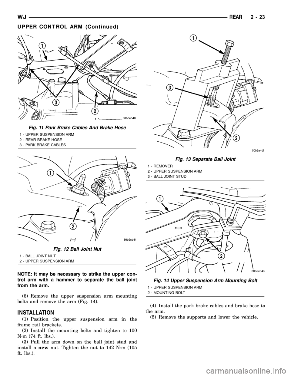
(3) Remove the park brake cables and brake hose
from the arm (Fig. 11).
(4) Remove the ball joint nut from the top of the
upper suspension arm (Fig. 12).
(5) Separate ball joint from the arm with Remover
8278 (Fig. 13).
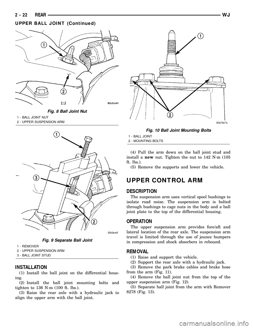
Fig. 8 Ball Joint Nut
1 - BALL JOINT NUT
2 - UPPER SUSPENSION ARM
Fig. 9 Separate Ball Joint
1 - REMOVER
2 - UPPER SUSPENSION ARM
3 - BALL JOINT STUD
Fig. 10 Ball Joint Mounting Bolts
1 - BALL JOINT
2 - MOUNTING BOLTS
2 - 22 REARWJ
UPPER BALL JOINT (Continued)
Page 44 of 2199
NOTE: It may be necessary to strike the upper con-
trol arm with a hammer to separate the ball joint
from the arm.
(6) Remove the upper suspension arm mounting
bolts and remove the arm (Fig. 14).
INSTALLATION
(1) Position the upper suspension arm in the
frame rail brackets.
(2) Install the mounting bolts and tighten to 100
N´m (74 ft. lbs.).
(3) Pull the arm down on the ball joint stud and
install anewnut. Tighten the nut to 142 N´m (105
ft. lbs.).(4) Install the park brake cables and brake hose to
the arm.
(5) Remove the supports and lower the vehicle.
Fig. 11 Park Brake Cables And Brake Hose
1 - UPPER SUSPENSION ARM
2 - REAR BRAKE HOSE
3 - PARK BRAKE CABLES
Fig. 12 Ball Joint Nut
1 - BALL JOINT NUT
2 - UPPER SUSPENSION ARM
Fig. 13 Separate Ball Joint
1 - REMOVER
2 - UPPER SUSPENSION ARM
3 - BALL JOINT STUD
Fig. 14 Upper Suspension Arm Mounting Bolt
1 - UPPER SUSPENSION ARM
2 - MOUNTING BOLT
WJREAR 2 - 23
UPPER CONTROL ARM (Continued)
Page 47 of 2199
DRIVELINE VIBRATION
Drive Condition Possible Cause Correction
Propeller Shaft Noise 1) Undercoating or other foreign material
on shaft.1) Clean exterior of shaft and wash with
solvent.
2) Loose U-joint clamp screws. 2) Install new clamps and screws and
tighten to proper torque.
3) Loose or bent U-joint yoke or
excessive runout.3) Install new yoke.
4) Incorrect driveline angularity. 4) Measure and correct driveline angles.
5) Rear spring center bolt not in seat. 5) Loosen spring u-bolts and seat center
bolt.
6) Worn U-joint bearings. 6) Install new U-joint.
7) Propeller shaft damaged or out of
balance.7) Installl new propeller shaft.
8) Broken rear spring. 8) Install new rear spring.
9) Excessive runout or unbalanced
condition.9) Re-index propeller shaft, test, and
evaluate.
10) Excessive drive pinion gear shaft
runout.10) Re-index propeller shaft and evaluate.
11) Excessive axle yoke deflection. 11) Inspect and replace yoke if necessary.
12) Excessive transfer case runout. 12) Inspect and repair as necessary.
Universal Joint Noise 1) Loose U-joint clamp screws. 1) Install new clamps and screws and
tighten to proper torque.
2) Lack of lubrication. 2) Replace U-joints as necessary.
BALANCE
NOTE: Removing and re-indexing the propeller
shaft 180É relative to the yoke may eliminate some
vibrations.
If propeller shaft is suspected of being unbalanced,
it can be verified with the following procedure:
(1) Raise the vehicle.
(2) Clean all the foreign material from the propel-
ler shaft and the universal joints.
(3) Inspect the propeller shaft for missing balance
weights, broken welds, and bent areas.If the pro-
peller shaft is bent, it must be replaced.
(4) Inspect the universal joints to ensure that they
are not worn, are properly installed, and are cor-
rectly aligned with the shaft.
(5) Check the universal joint clamp screws torque.
(6) Remove the wheels and tires. Install the wheel
lug nuts to retain the brake drums or rotors.
(7) Mark and number the shaft six inches from the
yoke end at four positions 90É apart.
(8) Run and accelerate the vehicle until vibration
occurs. Note the intensity and speed the vibration
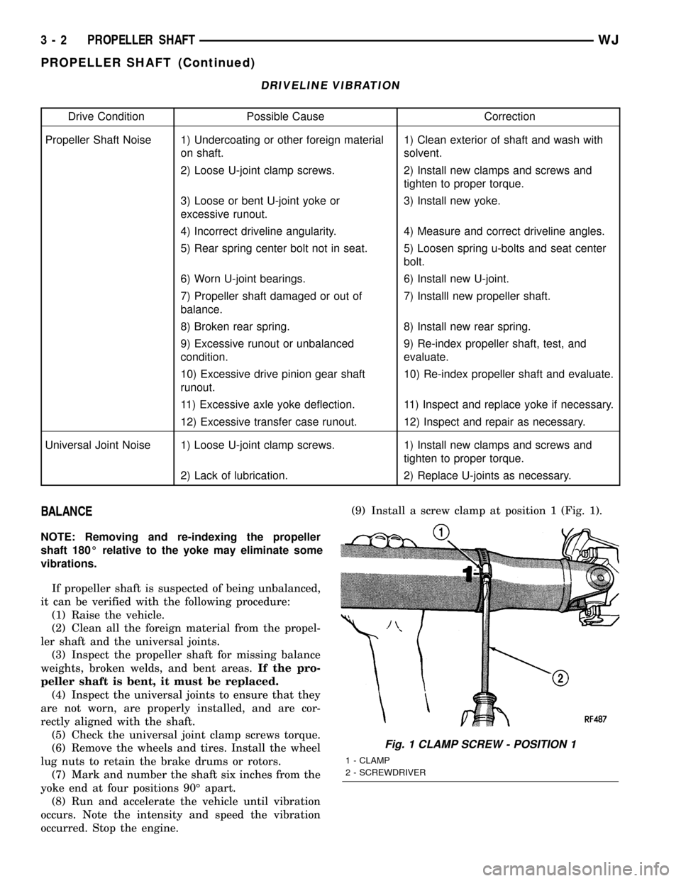
occurred. Stop the engine.(9) Install a screw clamp at position 1 (Fig. 1).
Fig. 1 CLAMP SCREW - POSITION 1
1 - CLAMP
2 - SCREWDRIVER
3 - 2 PROPELLER SHAFTWJ
PROPELLER SHAFT (Continued)
Page 50 of 2199
SPECIFICATIONS
TORQUE SPECIFICATIONS
DESCRIPTION N´m Ft. Lbs. In. Lbs.
Front Shaft - Companion Flange Bolts 32 24 -
4.7L Front Shaft - Axle Yoke Nuts 19 14 -
4.7L Front Shaft - Transfer Case Bolts 27 20 -
Rear Shaft - Yoke Nuts 19 14 -
SPECIAL TOOLS
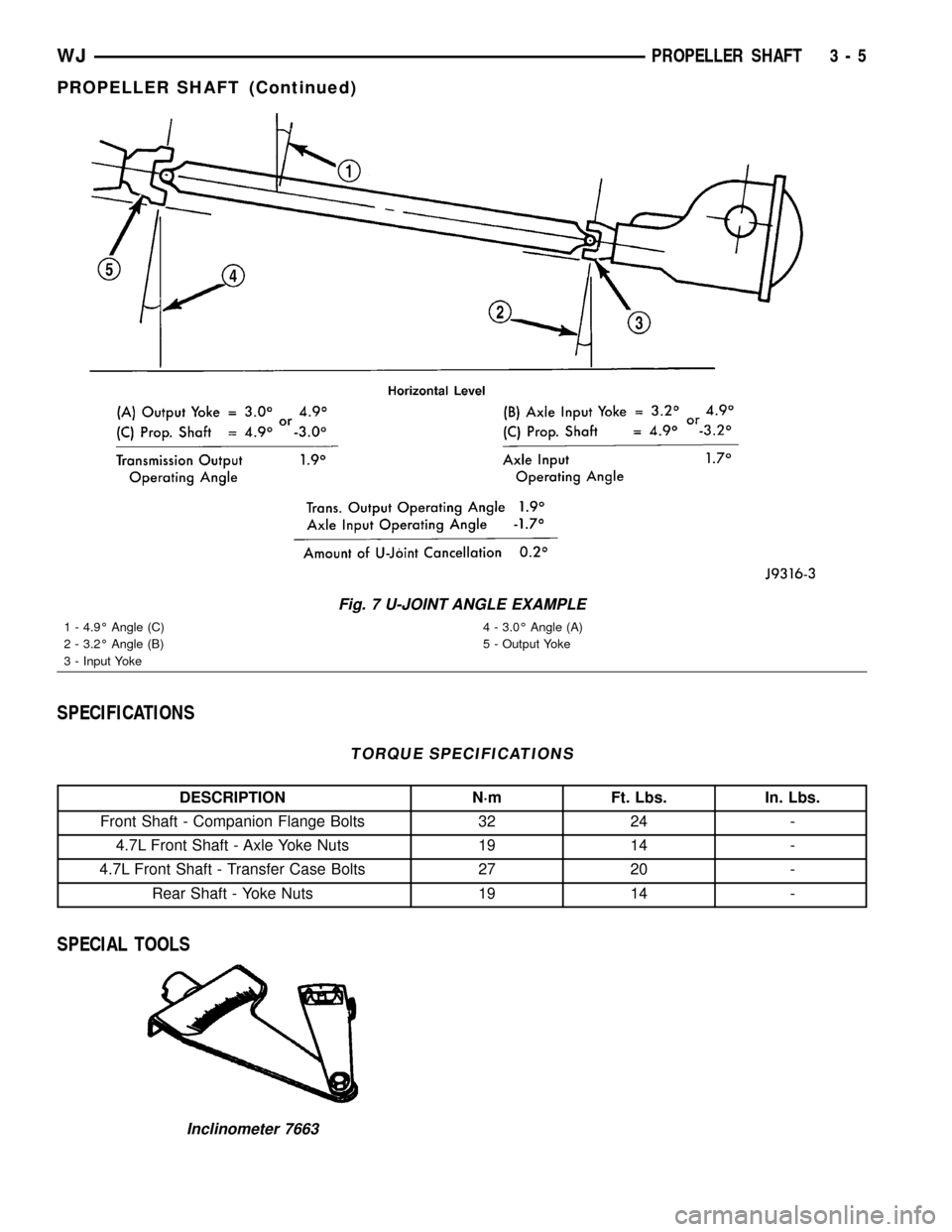
Fig. 7 U-JOINT ANGLE EXAMPLE
1 - 4.9É Angle (C)
2 - 3.2É Angle (B)
3 - Input Yoke4 - 3.0É Angle (A)
5 - Output Yoke
Inclinometer 7663
WJPROPELLER SHAFT 3 - 5
PROPELLER SHAFT (Continued)
Page 51 of 2199
PROPELLER SHAFT - FRONT
REMOVAL
NOTE: Different length propeller shafts are used for
different drivetrain applications. Ensure that the
correct propeller shaft is used.
(1) Place vehicle on floor or drive-on hoist with full
weight of vehicle on suspension.
(2) Shift the transmission and transfer case, if nec-
essary, into the Neutral position.
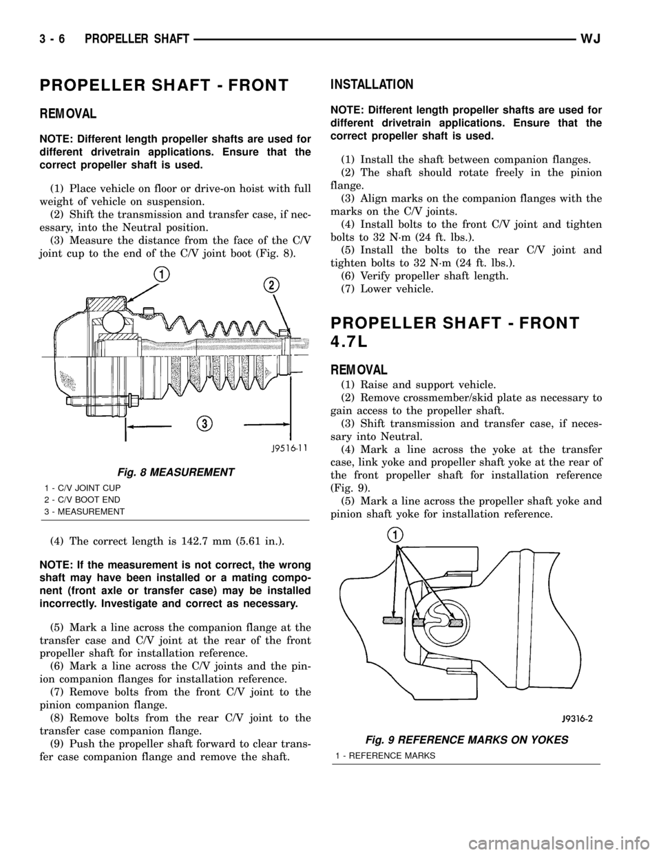
(3) Measure the distance from the face of the C/V
joint cup to the end of the C/V joint boot (Fig. 8).
(4) The correct length is 142.7 mm (5.61 in.).
NOTE: If the measurement is not correct, the wrong
shaft may have been installed or a mating compo-
nent (front axle or transfer case) may be installed
incorrectly. Investigate and correct as necessary.
(5) Mark a line across the companion flange at the
transfer case and C/V joint at the rear of the front
propeller shaft for installation reference.
(6) Mark a line across the C/V joints and the pin-
ion companion flanges for installation reference.
(7) Remove bolts from the front C/V joint to the
pinion companion flange.
(8) Remove bolts from the rear C/V joint to the
transfer case companion flange.
(9) Push the propeller shaft forward to clear trans-
fer case companion flange and remove the shaft.
INSTALLATION
NOTE: Different length propeller shafts are used for
different drivetrain applications. Ensure that the
correct propeller shaft is used.
(1) Install the shaft between companion flanges.
(2) The shaft should rotate freely in the pinion
flange.
(3) Align marks on the companion flanges with the
marks on the C/V joints.
(4) Install bolts to the front C/V joint and tighten
bolts to 32 N´m (24 ft. lbs.).
(5) Install the bolts to the rear C/V joint and
tighten bolts to 32 N´m (24 ft. lbs.).
(6) Verify propeller shaft length.
(7) Lower vehicle.
PROPELLER SHAFT - FRONT
4.7L
REMOVAL
(1) Raise and support vehicle.
(2) Remove crossmember/skid plate as necessary to
gain access to the propeller shaft.
(3) Shift transmission and transfer case, if neces-
sary into Neutral.
(4) Mark a line across the yoke at the transfer
case, link yoke and propeller shaft yoke at the rear of
the front propeller shaft for installation reference
(Fig. 9).
(5) Mark a line across the propeller shaft yoke and
pinion shaft yoke for installation reference.
Fig. 8 MEASUREMENT
1 - C/V JOINT CUP
2 - C/V BOOT END
3 - MEASUREMENT
Fig. 9 REFERENCE MARKS ON YOKES
1 - REFERENCE MARKS
3 - 6 PROPELLER SHAFTWJ
Page 52 of 2199
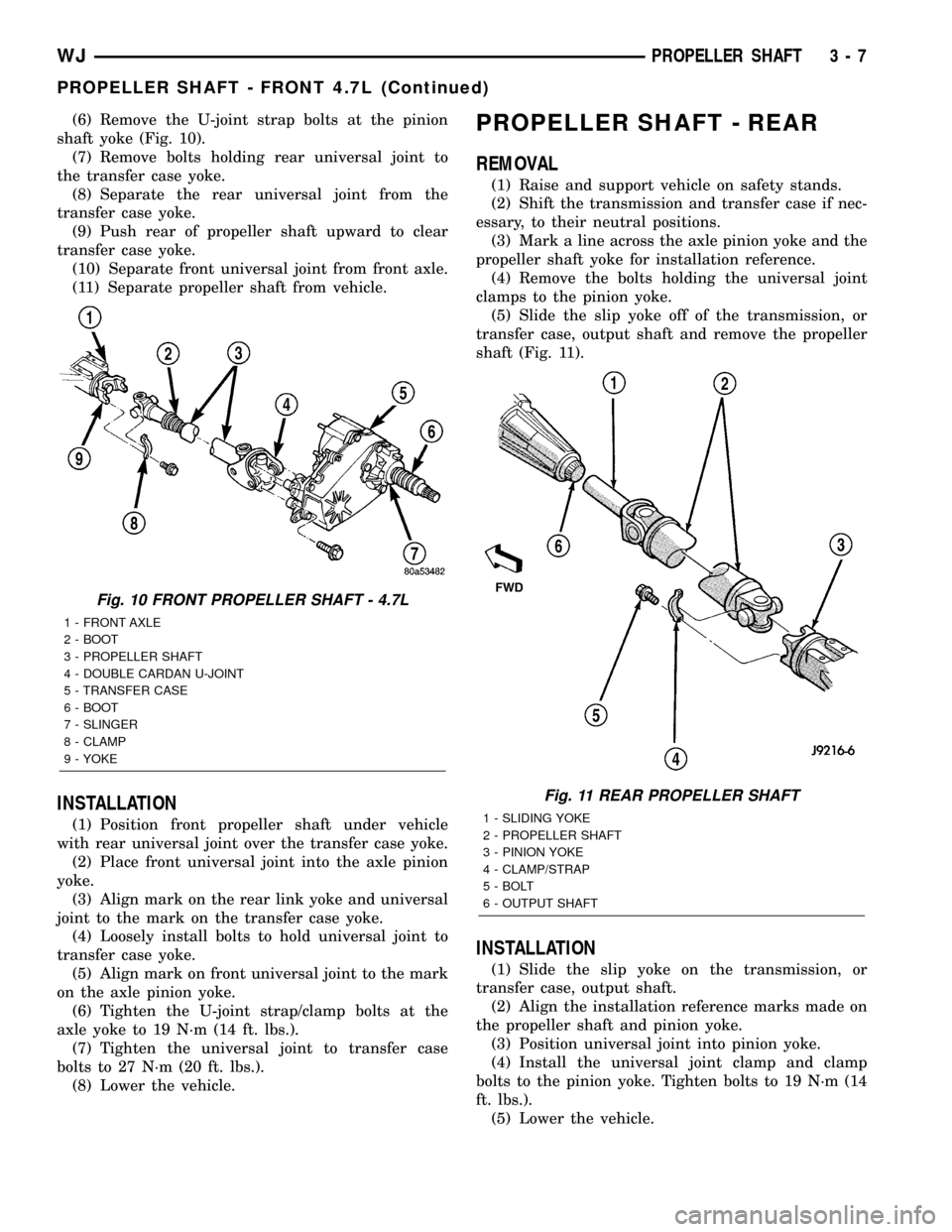
(6) Remove the U-joint strap bolts at the pinion
shaft yoke (Fig. 10).
(7) Remove bolts holding rear universal joint to
the transfer case yoke.
(8) Separate the rear universal joint from the
transfer case yoke.
(9) Push rear of propeller shaft upward to clear
transfer case yoke.
(10) Separate front universal joint from front axle.
(11) Separate propeller shaft from vehicle.
INSTALLATION
(1) Position front propeller shaft under vehicle
with rear universal joint over the transfer case yoke.
(2) Place front universal joint into the axle pinion
yoke.
(3) Align mark on the rear link yoke and universal
joint to the mark on the transfer case yoke.
(4) Loosely install bolts to hold universal joint to
transfer case yoke.
(5) Align mark on front universal joint to the mark
on the axle pinion yoke.
(6) Tighten the U-joint strap/clamp bolts at the
axle yoke to 19 N´m (14 ft. lbs.).
(7) Tighten the universal joint to transfer case
bolts to 27 N´m (20 ft. lbs.).
(8) Lower the vehicle.
PROPELLER SHAFT - REAR
REMOVAL
(1) Raise and support vehicle on safety stands.
(2) Shift the transmission and transfer case if nec-
essary, to their neutral positions.
(3) Mark a line across the axle pinion yoke and the
propeller shaft yoke for installation reference.
(4) Remove the bolts holding the universal joint
clamps to the pinion yoke.
(5) Slide the slip yoke off of the transmission, or
transfer case, output shaft and remove the propeller
shaft (Fig. 11).
INSTALLATION
(1) Slide the slip yoke on the transmission, or
transfer case, output shaft.
(2) Align the installation reference marks made on
the propeller shaft and pinion yoke.
(3) Position universal joint into pinion yoke.
(4) Install the universal joint clamp and clamp
bolts to the pinion yoke. Tighten bolts to 19 N´m (14
ft. lbs.).
(5) Lower the vehicle.
Fig. 10 FRONT PROPELLER SHAFT - 4.7L
1 - FRONT AXLE
2 - BOOT
3 - PROPELLER SHAFT
4 - DOUBLE CARDAN U-JOINT
5 - TRANSFER CASE
6 - BOOT
7 - SLINGER
8 - CLAMP
9 - YOKE
Fig. 11 REAR PROPELLER SHAFT
1 - SLIDING YOKE
2 - PROPELLER SHAFT
3 - PINION YOKE
4 - CLAMP/STRAP
5 - BOLT
6 - OUTPUT SHAFT
WJPROPELLER SHAFT 3 - 7
PROPELLER SHAFT - FRONT 4.7L (Continued)
Page 59 of 2199
FRONT TUBE AXLE
TABLE OF CONTENTS
page page
FRONT TUBE AXLE
REMOVAL.............................14INSTALLATION.........................14
FRONT TUBE AXLE
REMOVAL
(1) Raise and support the vehicle.
(2) Position a lifting device under the axle and
secure axle to lift.
(3) Remove the wheels and tires.
(4) Remove the brake rotors (Refer to 5 - BRAKES/
HYDRAULIC/MECHANICAL/ROTORS - REMOVAL)
and calipers.
(5) Disconnect wheel sensor wiring harness from
the vehicle wiring harness.
(6) Remove stabilizer bar links at the axle.
(7) Remove shock absorbers from axle brackets.
(8) Removet track bar.
(9) Remove tie rod and drag link from the steering
knuckle.
(10) Remove steering damper from the axle
bracket.
(11) Remove upper and lower suspension arms
from the axle brackets.
(12) Lower the lift enough to remove the axle. The
coil springs will drop with the axle.
(13) Remove the coil springs from the axle.
INSTALLATION
CAUTION: The weight of the vehicle must be sup-
ported by the springs before suspension arms and
track bar fasteners are tightened. If not at their nor-mal ride position, ride height and handling could be
affected.
(1) Install springs and retainer clips and tighten
retainer bolts to 21 N´m (16 ft. lbs.).
(2) Lift and position axle under the vehicle and
align it with the spring pads.
(3) Position upper and lower suspension arms in
the axle brackets and loosely install bolts and nuts.
(4) Install track bar to the axle bracket and loosely
install bolt.
(5) Install shock absorbers and tighten bolts to 23
N´m (17 ft. lbs.).
(6) Install stabilizer bar links to the axle brackets
and tighten nuts to 95 N´m (70 ft. lbs.).
(7) Install drag link and tie rod to the steering
knuckles.
(8) Install steering damper to the axle bracket and
tighten nut to 75 N´m (55 ft. lbs.).
(9) Install the brake rotors and calipers.
(10) Connect wheel speed sensor wiring harness, if
equipped.
(11) Install the wheel and tire assemblies.
(12) Remove lift from the axle and lower the vehi-
cle.
(13) Tighten upper suspension arm nuts to 75 N´m
(55 ft. lbs.). Tighten lower suspension arm nuts to
115 N´m (85 ft. lbs.).
(14) Tighten track bar bolt at the axle bracket to
100 N´m (74 ft. lbs.).
(15) Check the front wheel alignment.
3 - 14 FRONT TUBE AXLEWJ
Page 65 of 2199
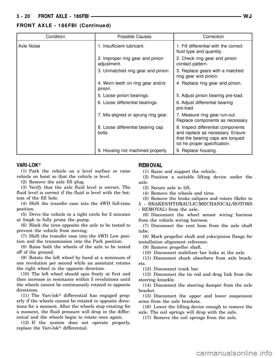
Condition Possible Causes Correction
Axle Noise 1. Insufficient lubricant. 1. Fill differential with the correct
fluid type and quantity.
2. Improper ring gear and pinion
adjustment.2. Check ring gear and pinion
contact pattern.
3. Unmatched ring gear and pinion. 3. Replace gears with a matched
ring gear and pinion.
4. Worn teeth on ring gear and/or
pinion.4. Replace ring gear and pinion.
5. Loose pinion bearings. 5. Adjust pinion bearing pre-load.
6. Loose differential bearings. 6. Adjust differential bearing
pre-load.
7. Mis-aligned or sprung ring gear. 7. Measure ring gear run-out.
Replace components as necessary.
8. Loose differential bearing cap
bolts.8. Inspect differential components
and replace as necessary. Ensure
that the bearing caps are torqued
tot he proper specification.
9. Housing not machined properly. 9. Replace housing.
VARI-LOKT
(1) Park the vehicle on a level surface or raise
vehicle on hoist so that the vehicle is level.
(2) Remove the axle fill plug.
(3) Verify that the axle fluid level is correct. The
fluid level is correct if the fluid is level with the bot-
tom of the fill hole.
(4) Shift the transfer case into the 4WD full-time
position.
(5) Drive the vehicle in a tight circle for 2 minutes
at 5mph to fully prime the pump.
(6) Block the tires opposite the axle to be tested to
prevent the vehicle from moving.
(7) Shift the transfer case into the 4WD Low posi-
tion and the transmission into the Park position.
(8) Raise both the wheels of the axle to be tested
off of the ground.
(9) Rotate the left wheel by hand at a minimum of
one revolution per second while an assistant rotates
the right wheel in the opposite direction.
(10) The left wheel should spin freely at first and
then increase in resistance within 5 revolutions until
the wheels cannot be continuously rotated in opposite
directions.
(11) The Vari-loktdifferential has engaged prop-
erly if the wheels cannot be rotated in opposite direc-
tions for a moment. After the wheels stop rotating for
a moment, the fluid pressure will drop in the differ-
ential and the wheels begin to rotate once again.
(12) If the system does not operate properly,
replace the Vari-loktdifferential.
REMOVAL
(1) Raise and support the vehicle.
(2) Position a suitable lifting device under the
axle.
(3) Secure axle to lift.
(4) Remove the wheels and tires.
(5) Remove the brake calipers and rotors (Refer to
5 - BRAKES/HYDRAULIC/MECHANICAL/ROTORS
- REMOVAL) from the axle.
(6) Disconnect the wheel sensor wiring harness
from the vehicle wiring harness.
(7) Disconnect the vent hose from the axle shaft
tube.
(8) Mark propeller shaft and yoke/pinion flange for
installation alignment reference.
(9) Remove propeller shaft.
(10) Disconnect stabilizer bar links at the axle.
(11) Disconnect shock absorbers from axle brack-
ets.
(12) Disconnect track bar.
(13) Disconnect the tie rod and drag link from the
steering knuckle.
(14) Disconnect the steering damper from the axle
bracket.
(15) Disconnect the upper and lower suspension
arms from the axle brackets.
(16) Lower the lifting device enough to remove the
axle. The coil springs will drop with the axle.
(17) Remove the coil springs from the axle.
3 - 20 FRONT AXLE - 186FBIWJ
FRONT AXLE - 186FBI (Continued)
Page 66 of 2199
INSTALLATION
CAUTION: The weight of the vehicle must be sup-
ported by the springs before suspension arms and
track bar fasteners can be tightened. If springs are
not at their normal ride position, ride height and
handling could be affected.
(1) Install the springs and retainer clips. Tighten
the retainer bolts to 21 N´m (16 ft. lbs.).
(2) Support the axle on a lifting device and posi-
tion axle under the vehicle.
(3) Raise the axle and align it with the spring
pads.
(4) Position the upper and lower suspension arms
in the axle brackets. Loosely install bolts and nuts to
hold suspension arms to the axle brackets.
(5) Install vent hose to the axle shaft tube.
(6) Install track bar in the axle bracket and install
the bolt loosely.
(7) Install shock absorbers and tighten the bolts to
23 N´m (17 ft. lbs.).
(8) Install stabilizer bar links to the axle brackets
and tighten the nuts to 95 N´m (70 ft. lbs.).
(9) Install drag link and tie rod to the steering
knuckles.
(10) Install steering damper to the axle bracket
and tighten the nut to 75 N´m (55 ft. lbs.).
(11) Install the brake rotors (Refer to 5 - BRAKES/
HYDRAULIC/MECHANICAL/ROTORS - INSTALLA-
TION) and calipers.
(12) Connect the wheel speed sensor wiring har-
ness to the vehicle wiring harness.
(13) Align the previously made marks on the pro-
peller shaft and the yoke/pinion flange.
(14) Install propeller shaft to pinion flange bolts ,
if equipped.
(15) Install propeller shaft to yoke straps and
bolts, if equipped.
(16) Check and fill axle lubricant.
(17) Install the wheel and tire assemblies.
(18) Remove the lifting device from the axle and
lower the vehicle.
(19) Tighten the upper suspension arm nuts to 75
N´m (55 ft. lbs.). Tighten the lower suspension arm
nuts to 115 N´m (85 ft. lbs.).
(20) Tighten the track bar bolt at the axle bracket
to 100 N´m (74 ft. lbs.).
(21) Check the front wheel alignment.
ADJUSTMENTS
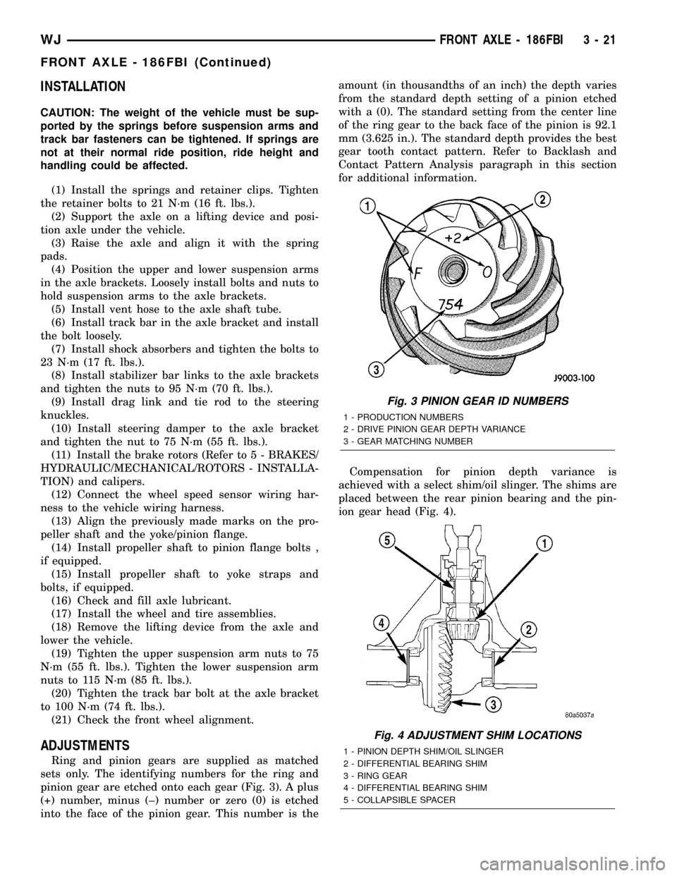
Ring and pinion gears are supplied as matched
sets only. The identifying numbers for the ring and
pinion gear are etched onto each gear (Fig. 3). A plus
(+) number, minus (±) number or zero (0) is etched
into the face of the pinion gear. This number is theamount (in thousandths of an inch) the depth varies
from the standard depth setting of a pinion etched
with a (0). The standard setting from the center line
of the ring gear to the back face of the pinion is 92.1
mm (3.625 in.). The standard depth provides the best
gear tooth contact pattern. Refer to Backlash and
Contact Pattern Analysis paragraph in this section
for additional information.
Compensation for pinion depth variance is
achieved with a select shim/oil slinger. The shims are
placed between the rear pinion bearing and the pin-
ion gear head (Fig. 4).
Fig. 3 PINION GEAR ID NUMBERS
1 - PRODUCTION NUMBERS
2 - DRIVE PINION GEAR DEPTH VARIANCE
3 - GEAR MATCHING NUMBER
Fig. 4 ADJUSTMENT SHIM LOCATIONS
1 - PINION DEPTH SHIM/OIL SLINGER
2 - DIFFERENTIAL BEARING SHIM
3 - RING GEAR
4 - DIFFERENTIAL BEARING SHIM
5 - COLLAPSIBLE SPACER
WJFRONT AXLE - 186FBI 3 - 21
FRONT AXLE - 186FBI (Continued)
Page 67 of 2199
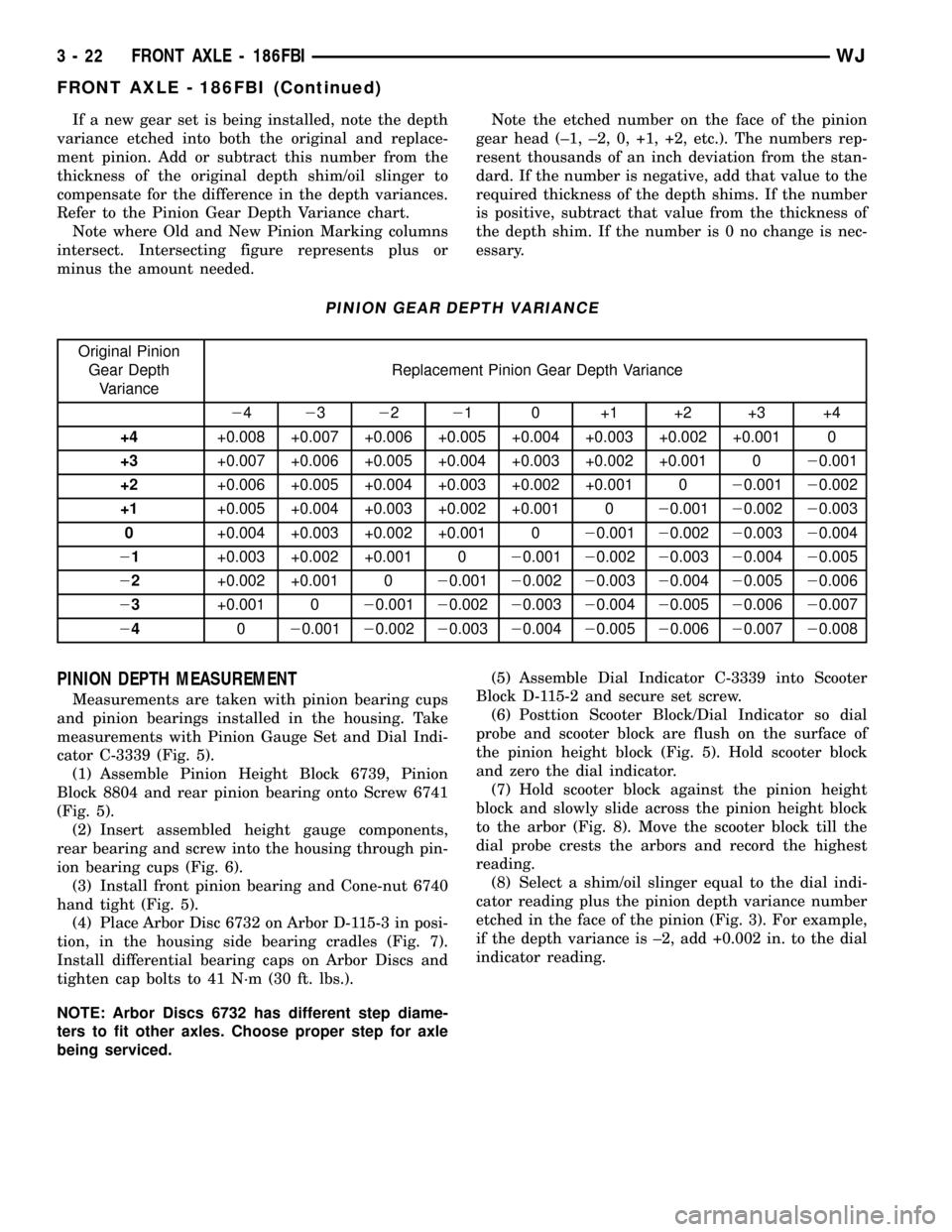
If a new gear set is being installed, note the depth
variance etched into both the original and replace-
ment pinion. Add or subtract this number from the
thickness of the original depth shim/oil slinger to
compensate for the difference in the depth variances.
Refer to the Pinion Gear Depth Variance chart.
Note where Old and New Pinion Marking columns
intersect. Intersecting figure represents plus or
minus the amount needed.Note the etched number on the face of the pinion
gear head (±1, ±2, 0, +1, +2, etc.). The numbers rep-
resent thousands of an inch deviation from the stan-
dard. If the number is negative, add that value to the
required thickness of the depth shims. If the number
is positive, subtract that value from the thickness of
the depth shim. If the number is 0 no change is nec-
essary.
PINION GEAR DEPTH VARIANCE
Original Pinion
Gear Depth
VarianceReplacement Pinion Gear Depth Variance
24232221 0 +1 +2 +3 +4
+4+0.008 +0.007 +0.006 +0.005 +0.004 +0.003 +0.002 +0.001 0
+3+0.007 +0.006 +0.005 +0.004 +0.003 +0.002 +0.001 020.001
+2+0.006 +0.005 +0.004 +0.003 +0.002 +0.001 020.00120.002
+1+0.005 +0.004 +0.003 +0.002 +0.001 020.00120.00220.003
0+0.004 +0.003 +0.002 +0.001 020.00120.00220.00320.004
21+0.003 +0.002 +0.001 020.00120.00220.00320.00420.005
22+0.002 +0.001 020.00120.00220.00320.00420.00520.006
23+0.001 020.00120.00220.00320.00420.00520.00620.007
24020.00120.00220.00320.00420.00520.00620.00720.008
PINION DEPTH MEASUREMENT
Measurements are taken with pinion bearing cups
and pinion bearings installed in the housing. Take
measurements with Pinion Gauge Set and Dial Indi-
cator C-3339 (Fig. 5).
(1) Assemble Pinion Height Block 6739, Pinion
Block 8804 and rear pinion bearing onto Screw 6741
(Fig. 5).
(2) Insert assembled height gauge components,
rear bearing and screw into the housing through pin-
ion bearing cups (Fig. 6).
(3) Install front pinion bearing and Cone-nut 6740
hand tight (Fig. 5).
(4) Place Arbor Disc 6732 on Arbor D-115-3 in posi-
tion, in the housing side bearing cradles (Fig. 7).
Install differential bearing caps on Arbor Discs and
tighten cap bolts to 41 N´m (30 ft. lbs.).
NOTE: Arbor Discs 6732 has different step diame-
ters to fit other axles. Choose proper step for axle
being serviced.(5) Assemble Dial Indicator C-3339 into Scooter
Block D-115-2 and secure set screw.
(6) Posttion Scooter Block/Dial Indicator so dial
probe and scooter block are flush on the surface of
the pinion height block (Fig. 5). Hold scooter block
and zero the dial indicator.
(7) Hold scooter block against the pinion height
block and slowly slide across the pinion height block
to the arbor (Fig. 8). Move the scooter block till the
dial probe crests the arbors and record the highest
reading.
(8) Select a shim/oil slinger equal to the dial indi-
cator reading plus the pinion depth variance number
etched in the face of the pinion (Fig. 3). For example,
if the depth variance is ±2, add +0.002 in. to the dial
indicator reading.
3 - 22 FRONT AXLE - 186FBIWJ
FRONT AXLE - 186FBI (Continued)