Lift studs JEEP GRAND CHEROKEE 2003 WJ / 2.G User Guide
[x] Cancel search | Manufacturer: JEEP, Model Year: 2003, Model line: GRAND CHEROKEE, Model: JEEP GRAND CHEROKEE 2003 WJ / 2.GPages: 2199, PDF Size: 76.01 MB
Page 1878 of 2199

DECKLID/HATCH/LIFTGATE/TAILGATE
TABLE OF CONTENTS
page page
EXTERIOR HANDLE
REMOVAL.............................5
INSTALLATION..........................5
FLIP-UP GLASS
REMOVAL.............................5
INSTALLATION..........................6
FLIP-UP GLASS LATCH
REMOVAL.............................6
INSTALLATION..........................6
FLIP-UP GLASS LATCH STRIKER
REMOVAL.............................7
INSTALLATION..........................7
FLIP-UP GLASS SWITCH
REMOVAL.............................7
INSTALLATION..........................7
HINGE
REMOVAL.............................7
INSTALLATION..........................7
LATCH
REMOVAL.............................8
INSTALLATION..........................8LATCH STRIKER
REMOVAL.............................8
INSTALLATION..........................8
LIFTGATE
REMOVAL.............................9
INSTALLATION..........................9
ADJUSTMENTS
LIFTGATE ADJUSTMENT................9
TRIM PANEL
REMOVAL
REMOVAL - LIFTGATE TRIM PANEL........9
REMOVAL - LOWER LIFTGATE OPENING
TRIM PANEL.........................10
INSTALLATION
INSTALLATION - LIFTGATE TRIM PANEL . . . 10
INSTALLATION - LOWER LIFTGATE
OPENING TRIM PANEL.................10
LIFTGATE INSULATOR
REMOVAL.............................10
INSTALLATION.........................10
EXTERIOR HANDLE
REMOVAL
(1) Remove the liftgate trim panel refer to (Refer
to 23 - BODY/DECKLID/HATCH/LIFTGATE/TAIL-
GATE/TRIM PANEL - REMOVAL).
(2) Remove the latch, outside handle linkage, and
power lock connector.
(3) Remove the fasteners attaching the outside
handle to the liftgate.
(4) Remove the outside handle from the liftgate.
INSTALLATION
(1) Position the outside handle on the liftgate.
(2) Install the fasteners attaching outside handle
to liftgate.
(3) Connect outside handle link and power lock
connector.
(4) Install liftgate trim panel, refer to (Refer to 23
- BODY/DECKLID/HATCH/LIFTGATE/TAILGATE/
TRIM PANEL - INSTALLATION).
FLIP-UP GLASS
REMOVAL
CAUTION: DO NOT DISCONNECT THE PROP ROD
CYLINDERS WITH THE LIFTGATE FLIP UP GLASS
CLOSED. THE PROP ROD PISTONS ARE OPER-
ATED BY HIGH PRESSURE GAS. THIS PRESSURE
COULD CAUSE DAMAGE AND/OR PERSONAL
INJURY IF THEY ARE REMOVED WHILE THE PIS-
TONS ARE COMPRESSED.
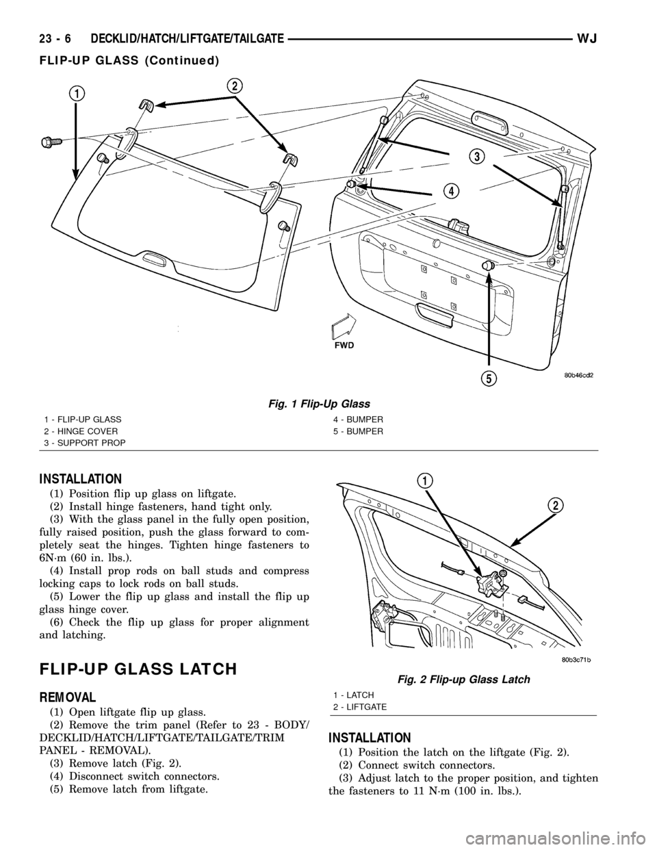
(1) Using a trim stick or other suitable device, sep-
arate the flip up glass hinge cover from the hinge on
the liftgate (Fig. 1).
(2) Open liftgate flip up glass. Support the glass
for ease of repair.
(3) Using a small flat blade or equivalent tool, gen-
tly pry open the locking caps on the end of the prop
rods.
(4) Remove prop rod cylinders from ball studs.
(5) Lower the flip up glass.
(6) Remove hinge fasteners from liftgate.
(7) Separate flip up glass from liftgate.
WJDECKLID/HATCH/LIFTGATE/TAILGATE 23 - 5
Page 1879 of 2199

INSTALLATION
(1) Position flip up glass on liftgate.
(2) Install hinge fasteners, hand tight only.
(3) With the glass panel in the fully open position,
fully raised position, push the glass forward to com-
pletely seat the hinges. Tighten hinge fasteners to
6N´m (60 in. lbs.).
(4) Install prop rods on ball studs and compress
locking caps to lock rods on ball studs.
(5) Lower the flip up glass and install the flip up
glass hinge cover.
(6) Check the flip up glass for proper alignment
and latching.
FLIP-UP GLASS LATCH
REMOVAL
(1) Open liftgate flip up glass.
(2) Remove the trim panel (Refer to 23 - BODY/
DECKLID/HATCH/LIFTGATE/TAILGATE/TRIM
PANEL - REMOVAL).
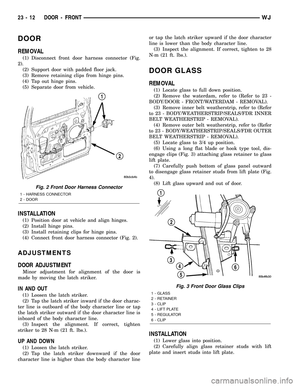
(3) Remove latch (Fig. 2).
(4) Disconnect switch connectors.
(5) Remove latch from liftgate.
INSTALLATION
(1) Position the latch on the liftgate (Fig. 2).
(2) Connect switch connectors.
(3) Adjust latch to the proper position, and tighten
the fasteners to 11 N´m (100 in. lbs.).
Fig. 1 Flip-Up Glass
1 - FLIP-UP GLASS
2 - HINGE COVER
3 - SUPPORT PROP4 - BUMPER
5 - BUMPER
Fig. 2 Flip-up Glass Latch
1-LATCH
2 - LIFTGATE
23 - 6 DECKLID/HATCH/LIFTGATE/TAILGATEWJ
FLIP-UP GLASS (Continued)
Page 1885 of 2199

DOOR
REMOVAL
(1) Disconnect front door harness connector (Fig.
2).
(2) Support door with padded floor jack.
(3) Remove retaining clips from hinge pins.
(4) Tap out hinge pins.
(5) Separate door from vehicle.
INSTALLATION
(1) Position door at vehicle and align hinges.
(2) Install hinge pins.
(3) Install retaining clips for hinge pins.
(4) Connect front door harness connector (Fig. 2).
ADJUSTMENTS
DOOR ADJUSTMENT
Minor adjustment for alignment of the door is
made by moving the latch striker.
IN AND OUT
(1) Loosen the latch striker.
(2) Tap the latch striker inward if the door charac-
ter line is outboard of the body character line or tap
the latch striker outward if the door character line is
inboard of the body character line.
(3) Inspect the alignment. If correct, tighten
striker to 28 N´m (21 ft. lbs.).
UP AND DOWN
(1) Loosen the latch striker.
(2) Tap the latch striker downward if the door
character line is higher than the body character lineor tap the latch striker upward if the door character
line is lower than the body character line.
(3) Inspect the alignment. If correct, tighten to 28
N´m (21 ft. lbs.).
DOOR GLASS
REMOVAL
(1) Locate glass to full down position.
(2) Remove the waterdam, refer to (Refer to 23 -
BODY/DOOR - FRONT/WATERDAM - REMOVAL).
(3) Remove inner belt weatherstrip, refer to (Refer
to 23 - BODY/WEATHERSTRIP/SEALS/FDR INNER
BELT WEATHERSTRIP - REMOVAL).
(4) Remove outer belt weatherstrip, refer to (Refer
to 23 - BODY/WEATHERSTRIP/SEALS/FDR OUTER
BELT WEATHERSTRIP - REMOVAL).
(5) Locate glass to 3/4 up position.
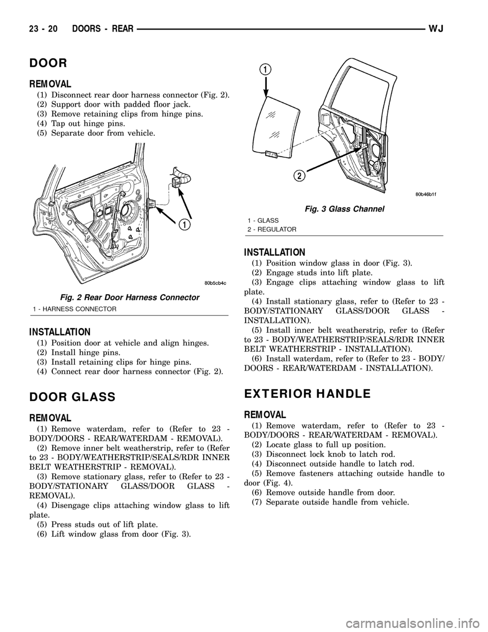
(6) Using a long flat blade or hook type tool, dis-
engage clips (Fig. 3) attaching glass retainer to glass
lift plate.
(7) Carefully push bottom of glass panel outward
to disengage glass retainer studs from lift plate (Fig.
4).
(8) Lift glass upward and out of door.
INSTALLATION
(1) Lower glass into position.
(2) Carefully align glass retainer studs with lift
plate and insert studs into lift plate.
Fig. 2 Front Door Harness Connector
1 - HARNESS CONNECTOR
2 - DOOR
Fig. 3 Front Door Glass Clips
1 - GLASS
2 - RETAINER
3 - CLIP
4 - LIFT PLATE
5 - REGULATOR
6 - CLIP
23 - 12 DOOR - FRONTWJ
Page 1893 of 2199

DOOR
REMOVAL
(1) Disconnect rear door harness connector (Fig. 2).
(2) Support door with padded floor jack.
(3) Remove retaining clips from hinge pins.
(4) Tap out hinge pins.
(5) Separate door from vehicle.
INSTALLATION
(1) Position door at vehicle and align hinges.
(2) Install hinge pins.
(3) Install retaining clips for hinge pins.
(4) Connect rear door harness connector (Fig. 2).
DOOR GLASS
REMOVAL
(1) Remove waterdam, refer to (Refer to 23 -
BODY/DOORS - REAR/WATERDAM - REMOVAL).
(2) Remove inner belt weatherstrip, refer to (Refer
to 23 - BODY/WEATHERSTRIP/SEALS/RDR INNER
BELT WEATHERSTRIP - REMOVAL).
(3) Remove stationary glass, refer to (Refer to 23 -
BODY/STATIONARY GLASS/DOOR GLASS -
REMOVAL).
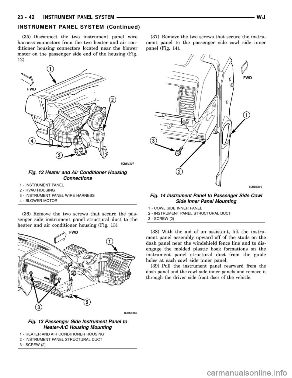
(4) Disengage clips attaching window glass to lift
plate.
(5) Press studs out of lift plate.
(6) Lift window glass from door (Fig. 3).
INSTALLATION
(1) Position window glass in door (Fig. 3).
(2) Engage studs into lift plate.
(3) Engage clips attaching window glass to lift
plate.
(4) Install stationary glass, refer to (Refer to 23 -
BODY/STATIONARY GLASS/DOOR GLASS -
INSTALLATION).
(5) Install inner belt weatherstrip, refer to (Refer
to 23 - BODY/WEATHERSTRIP/SEALS/RDR INNER
BELT WEATHERSTRIP - INSTALLATION).
(6) Install waterdam, refer to (Refer to 23 - BODY/
DOORS - REAR/WATERDAM - INSTALLATION).
EXTERIOR HANDLE
REMOVAL
(1) Remove waterdam, refer to (Refer to 23 -
BODY/DOORS - REAR/WATERDAM - REMOVAL).
(2) Locate glass to full up position.
(3) Disconnect lock knob to latch rod.
(4) Disconnect outside handle to latch rod.
(5) Remove fasteners attaching outside handle to
door (Fig. 4).
(6) Remove outside handle from door.
(7) Separate outside handle from vehicle.
Fig. 2 Rear Door Harness Connector
1 - HARNESS CONNECTOR
Fig. 3 Glass Channel
1 - GLASS
2 - REGULATOR
23 - 20 DOORS - REARWJ
Page 1915 of 2199

(35) Disconnect the two instrument panel wire
harness connectors from the two heater and air con-
ditioner housing connectors located near the blower
motor on the passenger side end of the housing (Fig.
12).
(36) Remove the two screws that secure the pas-
senger side instrument panel structural duct to the
heater and air conditioner housing (Fig. 13).(37) Remove the two screws that secure the instru-
ment panel to the passenger side cowl side inner
panel (Fig. 14).
(38) With the aid of an assistant, lift the instru-
ment panel assembly upward off of the studs on the
dash panel near the windshield fence line and to dis-
engage the molded plastic hook formations on the
instrument panel structural duct from the guide
holes at each cowl side inner panel.
(39)
Pull the instrument panel rearward from the
dash panel and the cowl side inner panels and remove it
through the driver side front door of the vehicle.
Fig. 12 Heater and Air Conditioner Housing
Connections
1 - INSTRUMENT PANEL
2 - HVAC HOUSING
3 - INSTRUMENT PANEL WIRE HARNESS
4 - BLOWER MOTOR
Fig. 13 Passenger Side Instrument Panel to
Heater-A/C Housing Mounting
1 - HEATER AND AIR CONDITIONER HOUSING
2 - INSTRUMENT PANEL STRUCTURAL DUCT
3 - SCREW (2)
Fig. 14 Instrument Panel to Passenger Side Cowl
Side Inner Panel Mounting
1 - COWL SIDE INNER PANEL
2 - INSTRUMENT PANEL STRUCTURAL DUCT
3 - SCREW (2)
23 - 42 INSTRUMENT PANEL SYSTEMWJ
INSTRUMENT PANEL SYSTEM (Continued)
Page 1968 of 2199

INSTALLATION
WARNING: REVIEW ALL WARNINGS AND CAU-
TIONS IN THIS GROUP BEFORE PRECEDING WITH
INSTALLATION.
CAUTION: Open a window before installing wind-
shield. This will avoid pressurizing the passenger
compartment. If a door or liftgate is slammed before
urethane is cured, water leaks can result.
The windshield fence should be cleaned of old ure-
thane bonding material. Support spacers should be
cleaned and properly installed on weld studs or
repair screws at bottom of windshield opening.
(1)
Place replacement windshield into windshield
opening. Position glass in the center of the opening
against the support spacers. Mark the glass at the sup-
port spacers with a grease pencil or masking tape and
ink pen to use as a reference for installation. Remove
replacement windshield from windshield opening (Fig. 6).
(2) Position the windshield inside up on a suitable
work surface with two padded, wood 10 cm by 10 cm
by 50 cm (4 in. by 4 in. by 20 in.) blocks, placed par-
allel 75 cm (2.5 ft.) apart (Fig. 7).
(3) Clean inside of windshield with Mopar Glass
Cleaner and lint-free cloth.
(4) Apply clear glass primer 25 mm (1 in.) wide
around edge of windshield. Wipe with clean/dry lint-
free cloth.
(5)
Apply black-out primer 15 mm (.75 in.) wide on
top and sides of windshield and 25 mm (1 in.) on bottom
of windshield. Allow at least three minutes drying time.
(6) Position windshield spacers on lower fence
above support spacers at the edge of the windshield
opening (Fig. 4).
(7)
Apply a 10 mm (0.4 in.) bead of urethane around
perimeter of windshield along the inside of the mold-
ings. Apply two beads along the bottom edge.
(8) Install upper molding onto windshield.
(9) Apply fence primer around the perimeter of the
windshield opening fence. Allow at least 18 minutes
drying time.
(10) With aid of a helper, position windshield over
windshield opening. Align reference marks at bottom
of windshield to support spacers.
(11) Slowly lower windshield glass to windshield
opening fence. Guide top molding into proper position
if necessary. Push windshield inward to fence spacers
at bottom and until top molding is flush to roof line.
(12) Clean excess urethane from exterior with
Mopar Super Clean or equivalent.
(13) Install windshield side moldings.
(14) Install cowl cover and wipers.
(15) Install inside rear view mirror.
(16) After urethane has cured, water test wind-
shield to verify repair.
Fig. 6 Center Windshield and Mark at Support Spacers
1 - A-PILLAR
2 - WINDSHIELD
3 - MARKS
4 - SUPPORT SPACER
5 - COWLFig. 7 Work Surface Set up and Molding Installation
1 - WINDSHIELD AND MOULDINGS
2-
URETHANE BEAD AROUND GLASS 7mm (.3 in.) FROM EDGE
3 - BLOCKS
Fig. 5 Cut Urethane Around WindshieldÐTypical
1 - COLD KNIFE
2 - WINDSHIELD
WJSTATIONARY GLASS 23 - 95
WINDSHIELD (Continued)