Tools JEEP GRAND CHEROKEE 2003 WJ / 2.G User Guide
[x] Cancel search | Manufacturer: JEEP, Model Year: 2003, Model line: GRAND CHEROKEE, Model: JEEP GRAND CHEROKEE 2003 WJ / 2.GPages: 2199, PDF Size: 76.01 MB
Page 68 of 2199
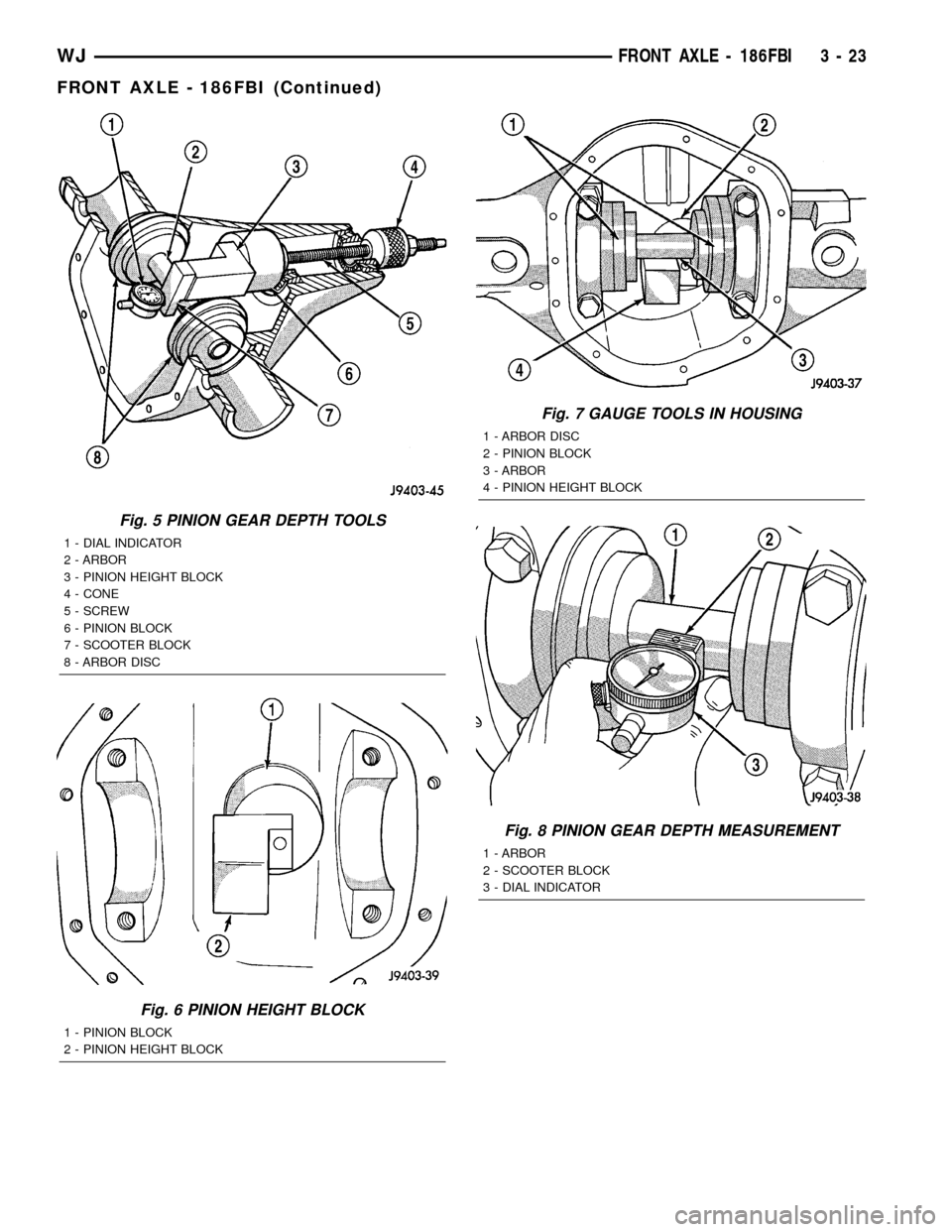
Fig. 5 PINION GEAR DEPTH TOOLS
1 - DIAL INDICATOR
2 - ARBOR
3 - PINION HEIGHT BLOCK
4 - CONE
5 - SCREW
6 - PINION BLOCK
7 - SCOOTER BLOCK
8 - ARBOR DISC
Fig. 6 PINION HEIGHT BLOCK
1 - PINION BLOCK
2 - PINION HEIGHT BLOCK
Fig. 7 GAUGE TOOLS IN HOUSING
1 - ARBOR DISC
2 - PINION BLOCK
3 - ARBOR
4 - PINION HEIGHT BLOCK
Fig. 8 PINION GEAR DEPTH MEASUREMENT
1 - ARBOR
2 - SCOOTER BLOCK
3 - DIAL INDICATOR
WJFRONT AXLE - 186FBI 3 - 23
FRONT AXLE - 186FBI (Continued)
Page 76 of 2199
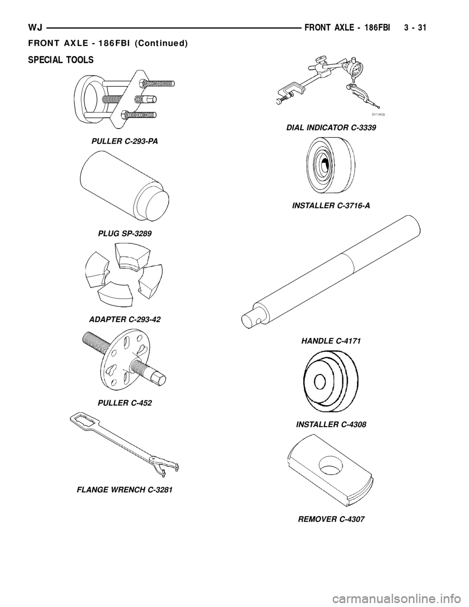
SPECIAL TOOLS
PULLER C-293-PA
PLUG SP-3289
ADAPTER C-293-42
PULLER C-452
FLANGE WRENCH C-3281
DIAL INDICATOR C-3339
INSTALLER C-3716-A
HANDLE C-4171
INSTALLER C-4308
REMOVER C-4307
WJFRONT AXLE - 186FBI 3 - 31
FRONT AXLE - 186FBI (Continued)
Page 80 of 2199
AXLE SHAFT SEALS
REMOVAL
(1) Raise and support vehicle.
(2) Remove axle shafts.
(3) Remove differential assembly.
(4) Remove inner axle shaft seals with a pry bay.
INSTALLATION
(1) Remove any sealer remaining from original
seals.
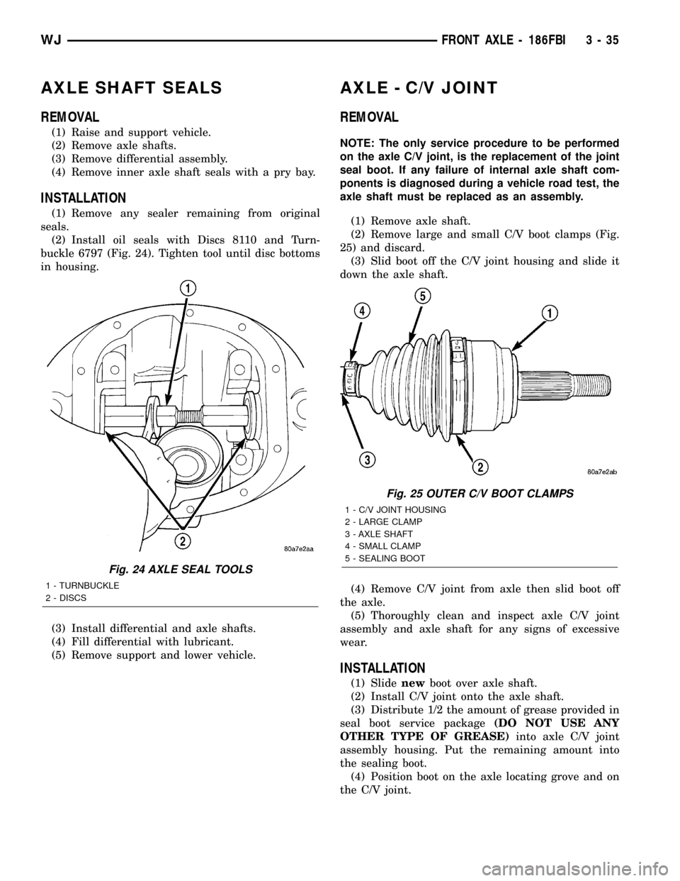
(2) Install oil seals with Discs 8110 and Turn-
buckle 6797 (Fig. 24). Tighten tool until disc bottoms
in housing.
(3) Install differential and axle shafts.
(4) Fill differential with lubricant.
(5) Remove support and lower vehicle.
AXLE - C/V JOINT
REMOVAL
NOTE: The only service procedure to be performed
on the axle C/V joint, is the replacement of the joint
seal boot. If any failure of internal axle shaft com-
ponents is diagnosed during a vehicle road test, the
axle shaft must be replaced as an assembly.
(1) Remove axle shaft.
(2) Remove large and small C/V boot clamps (Fig.
25) and discard.
(3) Slid boot off the C/V joint housing and slide it
down the axle shaft.
(4) Remove C/V joint from axle then slid boot off
the axle.
(5) Thoroughly clean and inspect axle C/V joint
assembly and axle shaft for any signs of excessive
wear.
INSTALLATION
(1) Slidenewboot over axle shaft.
(2) Install C/V joint onto the axle shaft.
(3) Distribute 1/2 the amount of grease provided in
seal boot service package(DO NOT USE ANY
OTHER TYPE OF GREASE)into axle C/V joint
assembly housing. Put the remaining amount into
the sealing boot.
(4) Position boot on the axle locating grove and on
the C/V joint.
Fig. 24 AXLE SEAL TOOLS
1 - TURNBUCKLE
2 - DISCS
Fig. 25 OUTER C/V BOOT CLAMPS
1 - C/V JOINT HOUSING
2 - LARGE CLAMP
3 - AXLE SHAFT
4 - SMALL CLAMP
5 - SEALING BOOT
WJFRONT AXLE - 186FBI 3 - 35
Page 84 of 2199
(6) Install propeller shaft with installation refer-
ence marks aligned.
(7) Fill differential with gear lubricant.
(8) Install brake rotors and calipers.
(9) Install wheel and tire assemblies.
(10) Lower the vehicle.
COLLAPSIBLE SPACER
REMOVAL
(1) Raise and support the vehicle.
(2) Remove wheel and tire assemblies.
(3) Remove brake rotors and calipers. Refer to 5
Brakes for procedures.
(4) Mark the propeller shaft and pinion companion
flange for installation reference.
(5) Remove propeller shaft from the pinion com-
panion flange.
(6) Rotate pinion gear a minimum of ten times and
verify pinion rotates smoothly.
(7) Record pinion gear rotating torque with a
torque wrench for installation reference.
(8) Remove pinion nut and washer. Using a short
piece of pipe and Spanner Wrench 6958 to hold the
pinion companion flange.
(9) Remove pinion companion flange with Remover
C-452 and Flange Wrench C-3281.
(10) Remove pinion shaft seal with Remover
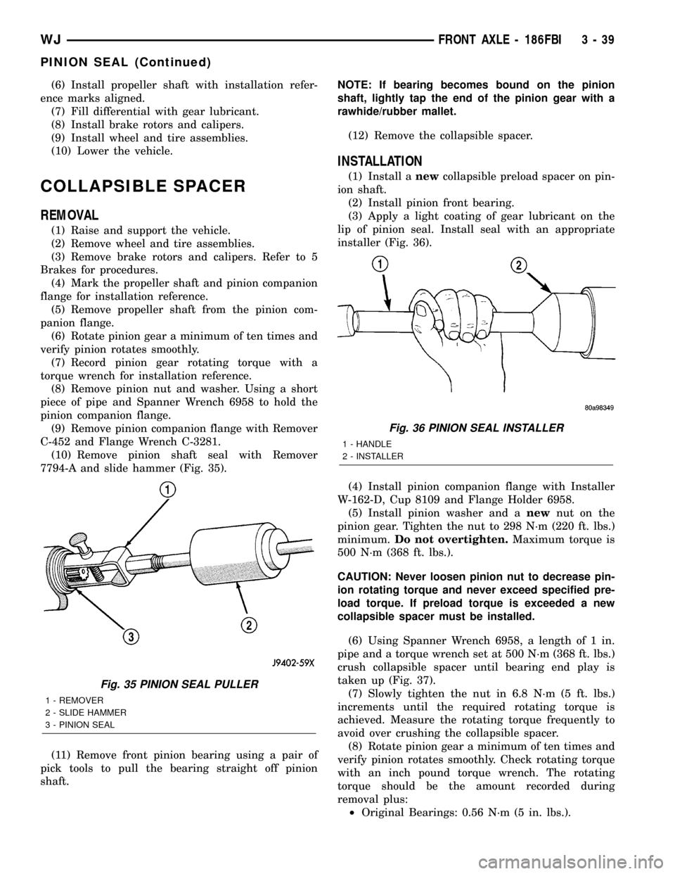
7794-A and slide hammer (Fig. 35).
(11) Remove front pinion bearing using a pair of
pick tools to pull the bearing straight off pinion
shaft.NOTE: If bearing becomes bound on the pinion
shaft, lightly tap the end of the pinion gear with a
rawhide/rubber mallet.
(12) Remove the collapsible spacer.
INSTALLATION
(1) Install anewcollapsible preload spacer on pin-
ion shaft.
(2) Install pinion front bearing.
(3) Apply a light coating of gear lubricant on the
lip of pinion seal. Install seal with an appropriate
installer (Fig. 36).
(4) Install pinion companion flange with Installer
W-162-D, Cup 8109 and Flange Holder 6958.
(5) Install pinion washer and anewnut on the
pinion gear. Tighten the nut to 298 N´m (220 ft. lbs.)
minimum.Do not overtighten.Maximum torque is
500 N´m (368 ft. lbs.).
CAUTION: Never loosen pinion nut to decrease pin-
ion rotating torque and never exceed specified pre-
load torque. If preload torque is exceeded a new
collapsible spacer must be installed.
(6) Using Spanner Wrench 6958, a length of 1 in.
pipe and a torque wrench set at 500 N´m (368 ft. lbs.)
crush collapsible spacer until bearing end play is
taken up (Fig. 37).
(7) Slowly tighten the nut in 6.8 N´m (5 ft. lbs.)
increments until the required rotating torque is
achieved. Measure the rotating torque frequently to
avoid over crushing the collapsible spacer.
(8) Rotate pinion gear a minimum of ten times and
verify pinion rotates smoothly. Check rotating torque
with an inch pound torque wrench. The rotating
torque should be the amount recorded during
removal plus:
²Original Bearings: 0.56 N´m (5 in. lbs.).
Fig. 35 PINION SEAL PULLER
1 - REMOVER
2 - SLIDE HAMMER
3 - PINION SEAL
Fig. 36 PINION SEAL INSTALLER
1 - HANDLE
2 - INSTALLER
WJFRONT AXLE - 186FBI 3 - 39
PINION SEAL (Continued)
Page 95 of 2199
REAR AXLE - 198RBI
TABLE OF CONTENTS
page page
REAR AXLE - 198RBI
DESCRIPTION.........................50
OPERATION...........................50
DIAGNOSIS AND TESTING................51
REMOVAL.............................55
INSTALLATION.........................56
ADJUSTMENTS........................56
SPECIFICATIONS.......................65
SPECIAL TOOLS.......................66
AXLE SHAFTS
REMOVAL.............................69
INSTALLATION.........................69
AXLE BEARINGS/SEALS
REMOVAL.............................69
INSTALLATION.........................70
PINION SEAL
REMOVAL.............................71
INSTALLATION.........................71
COLLAPSIBLE SPACER
REMOVAL.............................73INSTALLATION.........................73
DIFFERENTIAL
REMOVAL.............................75
DISASSEMBLY.........................77
ASSEMBLY............................77
INSTALLATION.........................77
DIFFERENTIAL-TRAC-LOC
DIAGNOSIS AND TESTING................79
DISASSEMBLY.........................79
CLEANING............................82
INSPECTION..........................82
ASSEMBLY............................82
DIFFERENTIAL CASE BEARINGS
REMOVAL.............................83
INSTALLATION.........................84
PINION GEAR/RING GEAR
REMOVAL.............................84
INSTALLATION.........................86
REAR AXLE - 198RBI
DESCRIPTION
The Rear Beam-design Iron (RBI) axle housing has
an iron center casting with axle shaft tubes extend-
ing from either side. The tubes are pressed into and
welded to the differential housing to form a one-piece
axle housing. The axles has semi-floating axle shafts,
meaning that loads are supported by the axle shaft
and bearings. The axle shafts are retained by bearing
retainer plates on the axles which are bolted to
flanges at the outboard end of the axle tubes.
The differential case is a one-piece design. Differ-
ential bearing preload and ring gear backlash is
adjusted by the use of selective spacer shims. Pinion
bearing preload is set and maintained by the use of a
collapsible spacer. A differential cover provides a
means for inspection and service.
Axles with optional Trac-Loktdifferential have a
one-piece differential case, and the same internal
components as a standard differential, plus two
clutch disc packs.
OPERATION
The axle receives power from the transmission/
transfer case through the rear propeller shaft. Therear propeller shaft is connected to the pinion gear
which rotates the differential through the gear mesh
with the ring gear bolted to the differential case. The
engine power is transmitted to the axle shafts
through the pinion mate and side gears. The side
gears are splined to the axle shafts.
STANDARD DIFFERENTIAL
During straight-ahead driving, the differential pin-
ion gears do not rotate on the pinion mate shaft. This
occurs because input torque applied to the gears is
divided and distributed equally between the two side
gears. As a result, the pinion gears revolve with the
pinion mate shaft but do not rotate around it (Fig. 1).
When turning corners, the outside wheel must
travel a greater distance than the inside wheel to
complete a turn. The difference must be compensated
for to prevent the tires from scuffing and skidding
through turns. To accomplish this, the differential
allows the axle shafts to turn at unequal speeds (Fig.
2). In this instance, the input torque applied to the
pinion gears is not divided equally. The pinion gears
now rotate around the pinion mate shaft in opposite
directions. This allows the side gear and axle shaft
attached to the outside wheel to rotate at a faster
speed.
3 - 50 REAR AXLE - 198RBIWJ
Page 103 of 2199
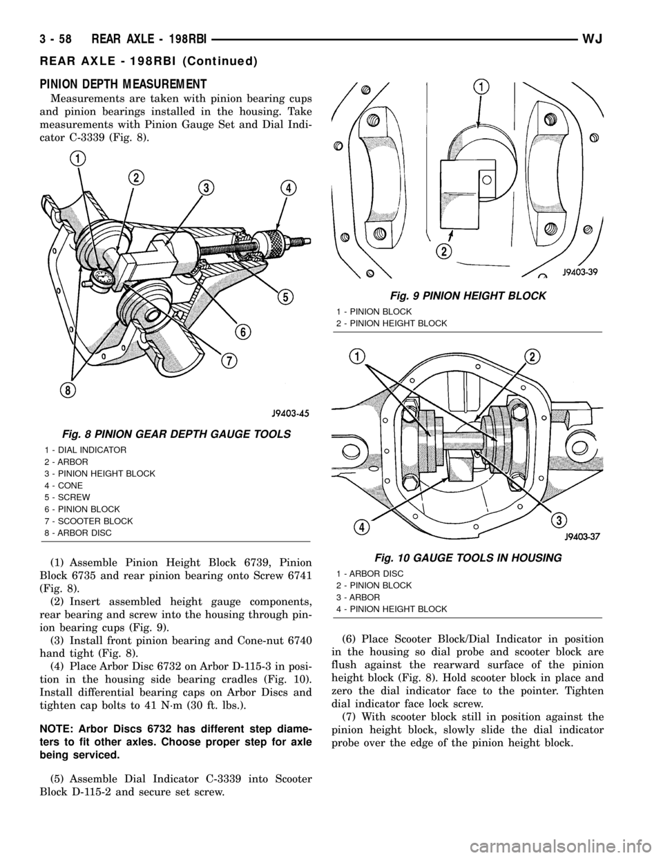
PINION DEPTH MEASUREMENT
Measurements are taken with pinion bearing cups
and pinion bearings installed in the housing. Take
measurements with Pinion Gauge Set and Dial Indi-
cator C-3339 (Fig. 8).
(1) Assemble Pinion Height Block 6739, Pinion
Block 6735 and rear pinion bearing onto Screw 6741
(Fig. 8).
(2) Insert assembled height gauge components,
rear bearing and screw into the housing through pin-
ion bearing cups (Fig. 9).
(3) Install front pinion bearing and Cone-nut 6740
hand tight (Fig. 8).
(4) Place Arbor Disc 6732 on Arbor D-115-3 in posi-
tion in the housing side bearing cradles (Fig. 10).
Install differential bearing caps on Arbor Discs and
tighten cap bolts to 41 N´m (30 ft. lbs.).
NOTE: Arbor Discs 6732 has different step diame-
ters to fit other axles. Choose proper step for axle
being serviced.
(5) Assemble Dial Indicator C-3339 into Scooter
Block D-115-2 and secure set screw.(6) Place Scooter Block/Dial Indicator in position
in the housing so dial probe and scooter block are
flush against the rearward surface of the pinion
height block (Fig. 8). Hold scooter block in place and
zero the dial indicator face to the pointer. Tighten
dial indicator face lock screw.
(7) With scooter block still in position against the
pinion height block, slowly slide the dial indicator
probe over the edge of the pinion height block.
Fig. 8 PINION GEAR DEPTH GAUGE TOOLS
1 - DIAL INDICATOR
2 - ARBOR
3 - PINION HEIGHT BLOCK
4 - CONE
5 - SCREW
6 - PINION BLOCK
7 - SCOOTER BLOCK
8 - ARBOR DISC
Fig. 9 PINION HEIGHT BLOCK
1 - PINION BLOCK
2 - PINION HEIGHT BLOCK
Fig. 10 GAUGE TOOLS IN HOUSING
1 - ARBOR DISC
2 - PINION BLOCK
3 - ARBOR
4 - PINION HEIGHT BLOCK
3 - 58 REAR AXLE - 198RBIWJ
REAR AXLE - 198RBI (Continued)
Page 111 of 2199
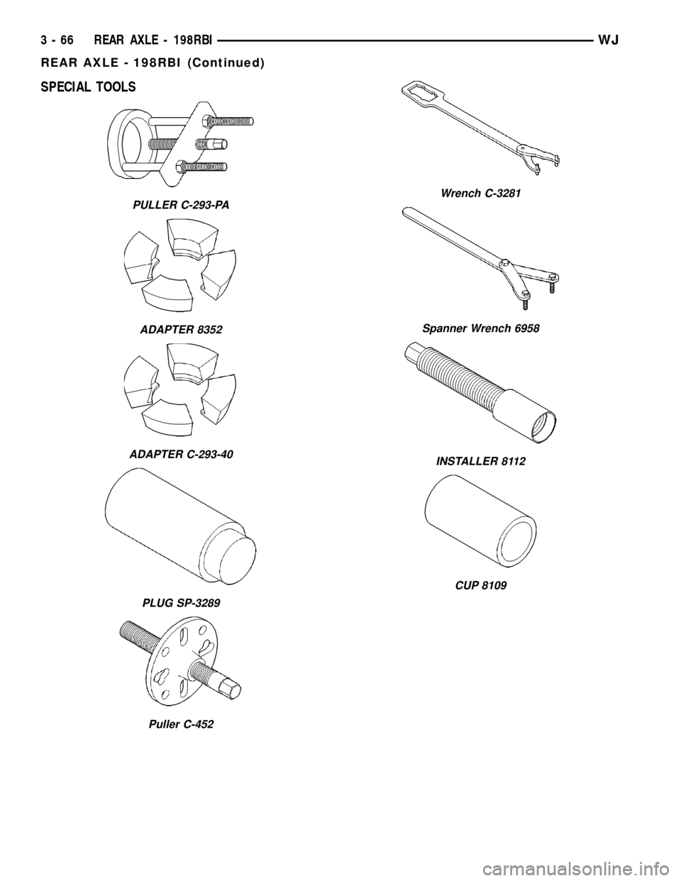
SPECIAL TOOLS
PULLER C-293-PA
ADAPTER 8352
ADAPTER C-293-40
PLUG SP-3289
Puller C-452
Wrench C-3281
Spanner Wrench 6958
INSTALLER 8112
CUP 8109
3 - 66 REAR AXLE - 198RBIWJ
REAR AXLE - 198RBI (Continued)
Page 112 of 2199
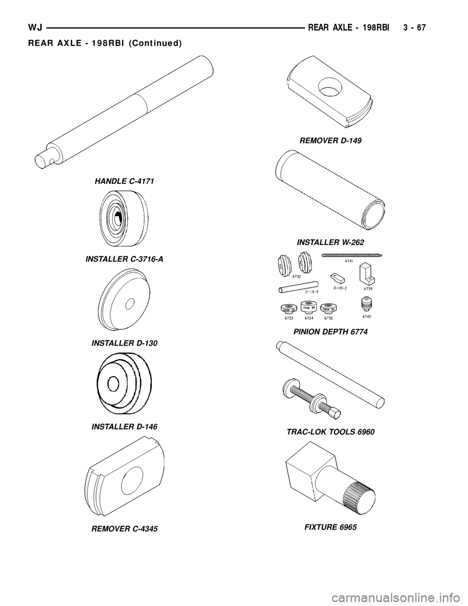
HANDLE C-4171
INSTALLER C-3716-A
INSTALLER D-130
INSTALLER D-146
REMOVER C-4345
REMOVER D-149
INSTALLER W-262
PINION DEPTH 6774
TRAC-LOK TOOLS 6960
FIXTURE 6965
WJREAR AXLE - 198RBI 3 - 67
REAR AXLE - 198RBI (Continued)
Page 118 of 2199
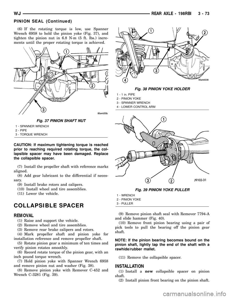
(6) If the rotating torque is low, use Spanner
Wrench 6958 to hold the pinion yoke (Fig. 37), and
tighten the pinion nut in 6.8 N´m (5 ft. lbs.) incre-
ments until the proper rotating torque is achieved.
CAUTION: If maximum tightening torque is reached
prior to reaching required rotating torque, the col-
lapsible spacer may have been damaged. Replace
the collapsible spacer.
(7) Install the propeller shaft with reference marks
aligned.
(8) Add gear lubricant to the differential if neces-
sary.
(9) Install brake rotors and calipers.
(10) Install wheel and tire assemblies.
(11) Lower the vehicle.
COLLAPSIBLE SPACER
REMOVAL
(1) Raise and support the vehicle.
(2) Remove wheel and tire assemblies.
(3) Remove rear brake calipers and rotors.
(4) Mark propeller shaft and pinion yoke for
installation reference and remove propeller shaft.
(5) Rotate pinion gear a minimum of ten times and
verify pinion rotates smoothly.
(6) Record rotate torque of the pinion gear, with an
inch pound torque wrench.
(7) Hold pinion yoke with Spanner Wrench 6958
and remove pinion nut and washer (Fig. 38).
(8) Remove pinion yoke with Remover C-452 and
Wrench C-3281 (Fig. 39).(9) Remove pinion shaft seal with Remover 7794-A
and slide hammer (Fig. 40).
(10) Remove front pinion bearing using a pair of
pick tools to pull the bearing off the pinion gear
shaft.
NOTE: If the pinion bearing becomes bound on the
pinion shaft, lightly tap the end of the shaft with a
rawhide/rubber mallet.
(11) Remove the collapsible spacer.
INSTALLATION
(1) Install anewcollapsible spacer on pinion
shaft.
(2) Install pinion front bearing on the pinion shaft.
Fig. 37 PINION SHAFT NUT
1 - SPANNER WRENCH
2 - PIPE
3 - TORQUE WRENCH
Fig. 38 PINION YOKE HOLDER
1 - 1 in. PIPE
2 - PINION YOKE
3 - SPANNER WRENCH
4 - LOWER CONTROL ARM
Fig. 39 PINION YOKE PULLER
1 - WRENCH
2 - PINION YOKE
3 - PULLER
WJREAR AXLE - 198RBI 3 - 73
PINION SEAL (Continued)
Page 135 of 2199
REAR AXLE - 226RBA
TABLE OF CONTENTS
page page
REAR AXLE - 226RBA
DESCRIPTION.........................90
OPERATION...........................90
DIAGNOSIS AND TESTING................92
REMOVAL.............................95
INSTALLATION.........................96
ADJUSTMENTS........................97
SPECIFICATIONS......................105
SPECIAL TOOLS.......................106
AXLE SHAFTS
REMOVAL............................109
INSTALLATION........................109
AXLE BEARINGS/SEALS
REMOVAL............................109
INSTALLATION........................110
PINION SEAL
REMOVAL............................111
INSTALLATION........................112
COLLAPSIBLE SPACER
REMOVAL............................113INSTALLATION........................114
DIFFERENTIAL
REMOVAL............................115
DISASSEMBLY........................117
ASSEMBLY...........................117
INSTALLATION........................117
DIFFERENTIAL - TRAC-LOK
DIAGNOSIS AND TESTING...............119
DISASSEMBLY........................119
CLEANING...........................121
INSPECTION.........................121
ASSEMBLY...........................121
DIFFERENTIAL CASE BEARINGS
REMOVAL............................123
INSTALLATION........................123
PINION GEAR/RING GEAR
REMOVAL............................124
INSTALLATION........................126
REAR AXLE - 226RBA
DESCRIPTION
The Rear Beam-design Aluminum (RBA) axle hous-
ing has an aluminum center casting (differential
housing) with axle shaft tubes extending from either
side. The tubes are pressed into the differential hous-
ing to form a one-piece axle housing. The axle has
semi-floating axle shafts, meaning that vehicle load
is supported by the axle shaft and bearings.
The differential case is a one-piece design. Differen-
tial bearing preload and ring gear backlash is adjusted
with selective shims. Pinion bearing preload is set and
maintained by the use of a collapsible spacer. The cover
provides a means for inspection and service.
Optional Trac-Loktdifferential differential has a
one-piece differential case, and the same internal
components as a standard differential, plus two
clutch disc packs.
Optional Vari-Loktdifferential has a one-piece dif-
ferential case which contains the gerotor pump
assembly and the clutch mechinism. The unit is ser-
viced only as an assembly.
OPERATION
The axle receives power from the transfer case
through the front propeller shaft. The front propellershaft is connected to the pinion gear which rotates
the differential through the gear mesh with the ring
gear bolted to the differential case. The engine power
is transmitted to the axle shafts through the pinion
mate and side gears. The side gears are splined to
the axle shafts.
STANDARD DIFFERENTIAL
During straight-ahead driving the differential pin-
ion gears do not rotate on the pinion mate shaft. This
occurs because input torque applied to the gears is
divided and distributed equally between the two side
gears. As a result, the pinion gears revolve with the
pinion mate shaft but do not rotate around it (Fig. 1).
When turning corners, the outside wheel must travel
a greater distance than the inside wheel to complete a
turn. The difference must be compensated for to prevent
the tires from scuffing and skidding through turns. To
accomplish this, the differential allows the axle shafts
to turn at unequal speeds (Fig. 2). In this instance, the
input torque applied to the pinion gears is not divided
equally. The pinion gears now rotate around the pinion
mate shaft in opposite directions. This allows the side
gear and axle shaft attached to the outside wheel to
rotate at a faster speed.
3 - 90 REAR AXLE - 226RBAWJ