fuse chart JEEP GRAND CHEROKEE 2003 WJ / 2.G Workshop Manual
[x] Cancel search | Manufacturer: JEEP, Model Year: 2003, Model line: GRAND CHEROKEE, Model: JEEP GRAND CHEROKEE 2003 WJ / 2.GPages: 2199, PDF Size: 76.01 MB
Page 383 of 2199

OK, repair the shorted circuit or component as
required and replace the faulty fuse.
(2) Turn the ignition switch to the On position.
Check for battery voltage at the fused ignition switch
output (run) fuse in the junction block. If OK, go to
Step 3. If not OK, repair the open fused ignition
switch output (run) circuit to the ignition switch as
required.
(3) Disconnect and isolate the battery negative
cable. Remove the lower center bezel from the instru-
ment panel and disconnect the instrument panel wire
harness connectors from both heated seat switch con-
nector receptacles. Check for continuity between the
ground circuit cavity of the instrument panel wire
harness connector for the inoperative heated seat
switch(es) and a good ground. There should be conti-
nuity. If OK, go to Step 4. If not OK, repair the open
ground circuit to ground as required.
(4) Reconnect the battery negative cable. Turn the
ignition switch to the On position. Check for battery
voltage at the fused ignition switch output (run) cir-
cuit cavity of the instrument panel wire harness con-
nector for the inoperative heated seat switch(es). If
OK, turn the ignition switch to the Off position, dis-
connect and isolate the battery negative cable, and go
to Step 5. If not OK, repair the open fused ignition
switch output (run) circuit to the junction block fuse
as required.
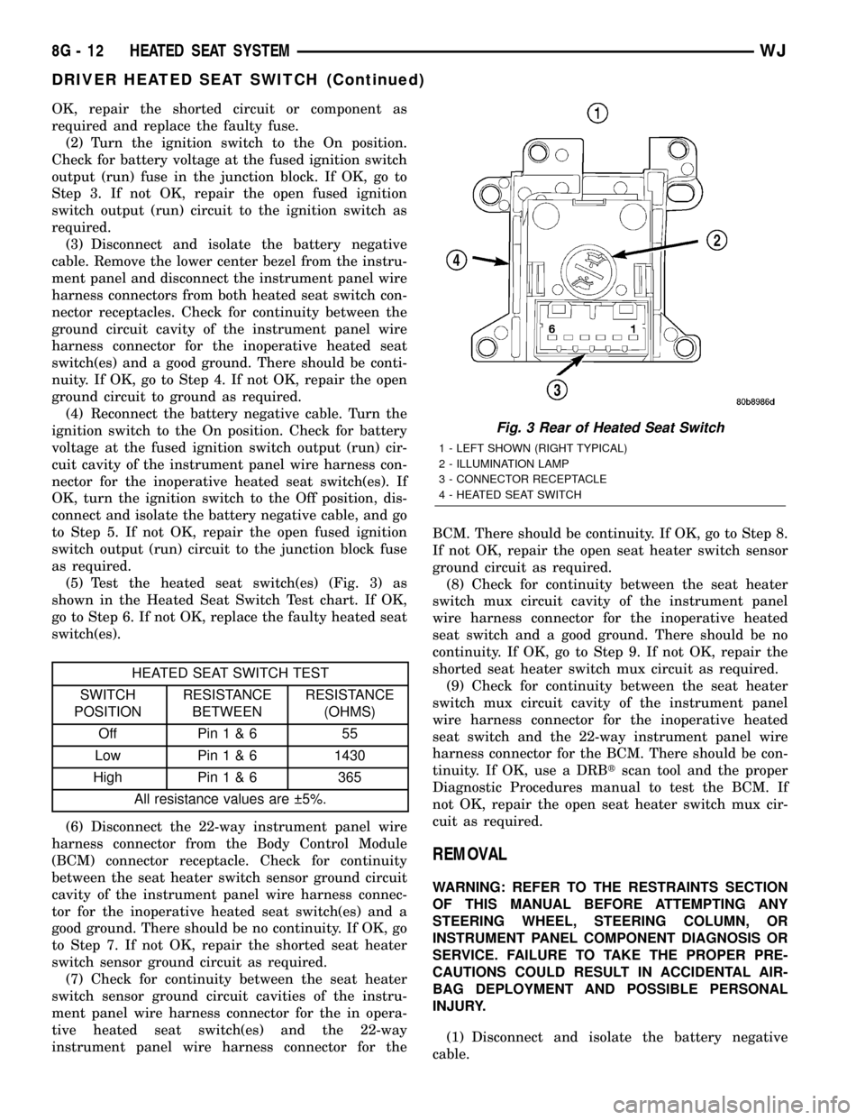
(5) Test the heated seat switch(es) (Fig. 3) as
shown in the Heated Seat Switch Test chart. If OK,
go to Step 6. If not OK, replace the faulty heated seat
switch(es).
HEATED SEAT SWITCH TEST
SWITCH
POSITIONRESISTANCE
BETWEENRESISTANCE
(OHMS)
Off Pin1&6 55
Low Pin1&61430
High Pin1&6 365
All resistance values are 5%.
(6) Disconnect the 22-way instrument panel wire
harness connector from the Body Control Module
(BCM) connector receptacle. Check for continuity
between the seat heater switch sensor ground circuit
cavity of the instrument panel wire harness connec-
tor for the inoperative heated seat switch(es) and a
good ground. There should be no continuity. If OK, go
to Step 7. If not OK, repair the shorted seat heater
switch sensor ground circuit as required.
(7) Check for continuity between the seat heater
switch sensor ground circuit cavities of the instru-
ment panel wire harness connector for the in opera-
tive heated seat switch(es) and the 22-way
instrument panel wire harness connector for theBCM. There should be continuity. If OK, go to Step 8.
If not OK, repair the open seat heater switch sensor
ground circuit as required.
(8) Check for continuity between the seat heater
switch mux circuit cavity of the instrument panel
wire harness connector for the inoperative heated
seat switch and a good ground. There should be no
continuity. If OK, go to Step 9. If not OK, repair the
shorted seat heater switch mux circuit as required.
(9) Check for continuity between the seat heater
switch mux circuit cavity of the instrument panel
wire harness connector for the inoperative heated
seat switch and the 22-way instrument panel wire
harness connector for the BCM. There should be con-
tinuity. If OK, use a DRBtscan tool and the proper
Diagnostic Procedures manual to test the BCM. If
not OK, repair the open seat heater switch mux cir-
cuit as required.
REMOVAL
WARNING: REFER TO THE RESTRAINTS SECTION
OF THIS MANUAL BEFORE ATTEMPTING ANY
STEERING WHEEL, STEERING COLUMN, OR
INSTRUMENT PANEL COMPONENT DIAGNOSIS OR
SERVICE. FAILURE TO TAKE THE PROPER PRE-
CAUTIONS COULD RESULT IN ACCIDENTAL AIR-
BAG DEPLOYMENT AND POSSIBLE PERSONAL
INJURY.
(1) Disconnect and isolate the battery negative
cable.
Fig. 3 Rear of Heated Seat Switch
1 - LEFT SHOWN (RIGHT TYPICAL)
2 - ILLUMINATION LAMP
3 - CONNECTOR RECEPTACLE
4 - HEATED SEAT SWITCH
8G - 12 HEATED SEAT SYSTEMWJ
DRIVER HEATED SEAT SWITCH (Continued)
Page 387 of 2199

OPERATION
There are three positions that can be selected with
each of the heated seat switches: Off, Low, or High.
When the top of the switch rocker is fully depressed,
the High position is selected and the high position
LED indicator illuminates. When the bottom of the
switch rocker is fully depressed, the Low position is
selected and the low position LED indicator illumi-
nates. When the switch rocker is moved to its neutral
position, Off is selected and both LED indicators are
extinguished.
Both switches provide separate resistor multi-
plexed hard wire inputs to the BCM to indicate the
selected switch position. The BCM monitors the
switch inputs and sends heated seat switch status
messages to the Heated Seat Module (HSM) or the
Memory Heated Seat Module (MHSM) over the Pro-
grammable Communications Interface (PCI) data
bus. The HSM or MHSM responds to the heated seat
switch status messages by controlling the output to
the seat heater elements of the selected seat. The
Low heat position set point is about 36É C (97É F),
and the High heat position set point is about 41É C
(105É F).
DIAGNOSIS AND TESTING - PASSENGER
HEATED SEAT SWITCH
For complete circuit diagrams, refer toWiring
Diagrams.
WARNING: REFER TO THE RESTRAINTS SECTION
OF THIS MANUAL BEFORE ATTEMPTING ANY
STEERING WHEEL, STEERING COLUMN, OR
INSTRUMENT PANEL COMPONENT DIAGNOSIS OR
SERVICE. FAILURE TO TAKE THE PROPER PRE-
CAUTIONS COULD RESULT IN ACCIDENTAL AIR-
BAG DEPLOYMENT AND POSSIBLE PERSONAL
INJURY.
(1) Check the fused ignition switch output (run)
fuse in the junction block. If OK, go to Step 2. If not
OK, repair the shorted circuit or component as
required and replace the faulty fuse.
(2) Turn the ignition switch to the On position.
Check for battery voltage at the fused ignition switch
output (run) fuse in the junction block. If OK, go to
Step 3. If not OK, repair the open fused ignition
switch output (run) circuit to the ignition switch as
required.
(3) Disconnect and isolate the battery negative
cable. Remove the lower center bezel from the instru-
ment panel and disconnect the instrument panel wire
harness connectors from both heated seat switch con-
nector receptacles. Check for continuity between the
ground circuit cavity of the instrument panel wire
harness connector for the inoperative heated seatswitch(es) and a good ground. There should be conti-
nuity. If OK, go to Step 4. If not OK, repair the open
ground circuit to ground as required.
(4) Reconnect the battery negative cable. Turn the
ignition switch to the On position. Check for battery
voltage at the fused ignition switch output (run) cir-
cuit cavity of the instrument panel wire harness con-
nector for the inoperative heated seat switch(es). If
OK, turn the ignition switch to the Off position, dis-
connect and isolate the battery negative cable, and go
to Step 5. If not OK, repair the open fused ignition
switch output (run) circuit to the junction block fuse
as required.
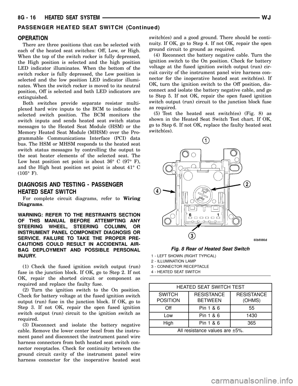
(5) Test the heated seat switch(es) (Fig. 8) as
shown in the Heated Seat Switch Test chart. If OK,
go to Step 6. If not OK, replace the faulty heated seat
switch(es).
HEATED SEAT SWITCH TEST
SWITCH
POSITIONRESISTANCE
BETWEENRESISTANCE
(OHMS)
Off Pin1&6 55
Low Pin1&61430
High Pin1&6 365
All resistance values are 5%.
Fig. 8 Rear of Heated Seat Switch
1 - LEFT SHOWN (RIGHT TYPICAL)
2 - ILLUMINATION LAMP
3 - CONNECTOR RECEPTACLE
4 - HEATED SEAT SWITCH
8G - 16 HEATED SEAT SYSTEMWJ
PASSENGER HEATED SEAT SWITCH (Continued)
Page 513 of 2199

DIAGNOSIS AND TESTING - SIDEVIEW
MIRROR
For complete circuit diagrams, refer to the appro-
priate wiring information. The wiring information
includes wiring diagrams, proper wire and connector
repair procedures, details of wire harness routing
and retention, connector pin-out information and
location views for the various wire harness connec-
tors, splices and grounds.
BOTH MIRRORS INOPERATIVE
(1) Check the operation of the power lock switch
on the driver side front door. If all of the doors lock
and unlock, replace the faulty Driver Door Module
(DDM). If not OK, go to Step 2.
(2) Check the operation of the power lock switch
on the passenger side front door. If all of the doors
lock and unlock, replace the faulty DDM. If not OK,
go to Step 3.
(3) Check the fused B(+) fuse in the Power Distri-
bution Center (PDC). If OK, go to Step 4. If not OK,
repair the shorted circuit or component as required
and replace the faulty fuse.
(4) Check for battery voltage at the fused B(+) fuse
in the PDC. If OK, go to Step 5. If not OK, repair the
open fused B(+) circuit to the battery as required.
(5) Disconnect and isolate the battery negative
cable. Remove the trim panel from the driver side
front door. Disconnect the 15-way door wire harness
connector from the DDM connector receptacle. Check
for continuity between the ground circuit cavity of
the 15-way door wire harness connector for the DDM
and a good ground. There should be continuity. If
OK, go to Step 6. If not OK, repair the open ground
circuit to ground as required.
(6)
Reconnect the battery negative cable. Check for
battery voltage at the fused B(+) circuit cavity of the
15-way door wire harness connector for the DDM. If
OK, replace the faulty DDM. If not OK, repair the open
fused B(+) circuit to the fuse in the PDC as required.
ONE MIRROR INOPERATIVE
(1) If the one inoperative mirror is on the passen-
ger side, go to Step 2. If the one inoperative mirror is
on the driver side, go to Step 3.
(2)
Check if the passenger front door will lock and
unlock using the power lock switch on the driver side
front door. If OK, go to Step 3. If not OK, go to Step 6.
(3) Disconnect and isolate the battery negative
cable. Remove the trim panel from the front door.
Disconnect the 12-way mirror wire harness connector
from the door wire harness connector.
(4) Using two jumper wires, test the mirror as
shown in the Mirror Test chart (Fig. 2). If the mirror
tests OK, go to Step 5. If the mirror does not test
OK, replace the faulty mirror.(5) Disconnect the 12-way door wire harness con-
nector from the door module connector receptacle.
Check all of the circuits of the door wire harness
between the connector for the mirror and the connec-
tor for the door module for opens or shorts. If all of
the circuits are OK, replace the faulty door module.
If any of the circuits are not OK, repair the open or
shorted circuit(s) as required.
(6) Use a DRB scan tool and the proper Diagnostic
Procedures manual to test and repair the faulty Pro-
grammable Communications Interface (PCI) data bus
communication between the two door modules.
NO MIRROR HEAT
If one or both mirror heaters are inoperative,
(Refer to 8 - ELECTRICAL/HEATED MIRRORS -
DESCRIPTION).
(1) Disconnect and isolate the battery negative
cable. Remove the front door trim panel on the side
of the inoperative mirror heater.
(2) Disconnect the 12-way door wire harness con-
nector from the door module connector receptacle.
Check for continuity between the heater switched
ground circuit cavity and the heater 12V supply cir-
cuit cavity of the 12-way door wire harness connector
Fig. 2 Mirror Test
POWER MIRROR TEST TABLE
APPLY 12
VOLTS TO:APPLY
GROUND TO:MIRROR
REACTION
DRIVER SIDE
1 7 LEFT
7 1 RIGHT
87UP
7 8 DOWN
PASSENGER SIDE
1 7 LEFT
7 1 RIGHT
87UP
7 8 DOWN
8N - 16 POWER MIRRORSWJ
SIDEVIEW MIRROR (Continued)
Page 661 of 2199

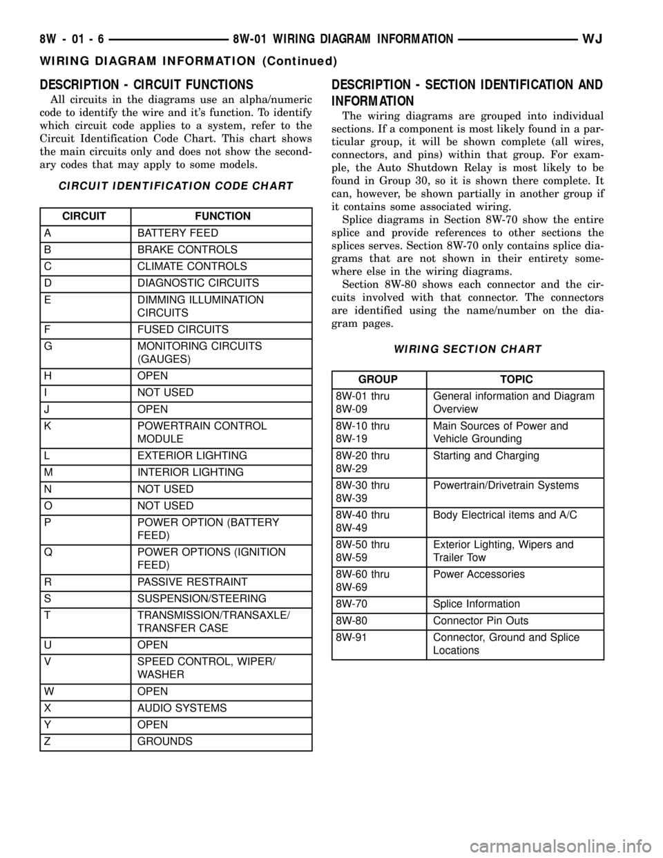
DESCRIPTION - CIRCUIT FUNCTIONS
All circuits in the diagrams use an alpha/numeric
code to identify the wire and it's function. To identify
which circuit code applies to a system, refer to the
Circuit Identification Code Chart. This chart shows
the main circuits only and does not show the second-
ary codes that may apply to some models.
CIRCUIT IDENTIFICATION CODE CHART
CIRCUIT FUNCTION
A BATTERY FEED
B BRAKE CONTROLS
C CLIMATE CONTROLS
D DIAGNOSTIC CIRCUITS
E DIMMING ILLUMINATION
CIRCUITS
F FUSED CIRCUITS
G MONITORING CIRCUITS
(GAUGES)
H OPEN
I NOT USED
J OPEN
K POWERTRAIN CONTROL
MODULE
L EXTERIOR LIGHTING
M INTERIOR LIGHTING
N NOT USED
O NOT USED
P POWER OPTION (BATTERY
FEED)
Q POWER OPTIONS (IGNITION
FEED)
R PASSIVE RESTRAINT
S SUSPENSION/STEERING
T TRANSMISSION/TRANSAXLE/
TRANSFER CASE
U OPEN
V SPEED CONTROL, WIPER/
WASHER
W OPEN
X AUDIO SYSTEMS
Y OPEN
Z GROUNDS
DESCRIPTION - SECTION IDENTIFICATION AND
INFORMATION
The wiring diagrams are grouped into individual
sections. If a component is most likely found in a par-
ticular group, it will be shown complete (all wires,
connectors, and pins) within that group. For exam-
ple, the Auto Shutdown Relay is most likely to be
found in Group 30, so it is shown there complete. It
can, however, be shown partially in another group if
it contains some associated wiring.
Splice diagrams in Section 8W-70 show the entire
splice and provide references to other sections the
splices serves. Section 8W-70 only contains splice dia-
grams that are not shown in their entirety some-
where else in the wiring diagrams.
Section 8W-80 shows each connector and the cir-
cuits involved with that connector. The connectors
are identified using the name/number on the dia-
gram pages.
WIRING SECTION CHART
GROUP TOPIC
8W-01 thru
8W-09General information and Diagram
Overview
8W-10 thru
8W-19Main Sources of Power and
Vehicle Grounding
8W-20 thru
8W-29Starting and Charging
8W-30 thru
8W-39Powertrain/Drivetrain Systems
8W-40 thru
8W-49Body Electrical items and A/C
8W-50 thru
8W-59Exterior Lighting, Wipers and
Trailer Tow
8W-60 thru
8W-69Power Accessories
8W-70 Splice Information
8W-80 Connector Pin Outs
8W-91 Connector, Ground and Splice
Locations
8W - 01 - 6 8W-01 WIRING DIAGRAM INFORMATIONWJ
WIRING DIAGRAM INFORMATION (Continued)
Page 1969 of 2199

SUNROOF
TABLE OF CONTENTS
page page
SUNROOF
DESCRIPTION.........................96
DIAGNOSIS AND TESTING - SUNROOF......96
DRAIN TUBE
REMOVAL............................100
INSTALLATION........................100
CONTROL MODULE
REMOVAL............................101
INSTALLATION........................101
DRIVE MOTOR
REMOVAL............................101
INSTALLATION........................101
WIND DEFLECTOR
REMOVAL............................102INSTALLATION........................102
GLASS PANEL
REMOVAL............................102
INSTALLATION........................103
ADJUSTMENTS
ADJUSTMENTS - FIT.................103
ADJUSTMENT - TIMING...............103
SUNSHADE
REMOVAL............................103
INSTALLATION........................103
HOUSING ASSEMBLY
REMOVAL............................104
INSTALLATION........................104
SUNROOF
DESCRIPTION
WARNING: Keep fingers and other body parts out
of sunroof opening at all times.
The sunroof features a power sliding glass panel
and a sunshade which can be manually positioned
anywhere along its travel, rearward of glass panel
front edge.
The sunroof is electrically operated from a switch
located on the mini overhead console. To operate the
sunroof the ignition switch must be in the On/Run
position. The sunroof has both manual and Express
Open modes of operation when opening. To open the
sunroof in the Express Open mode, the switch is
pressed rearward for less than1 second.This causes
the sunroof glass to automatically retract and stop at
a position slightly forward of full open that reduces
low speed wind buffeting. The sunroof can also be
opened manually by pressing and holding the switch
rearward. Once the switch is held reward for more
than1 second,the glass will retract in the manual
mode. Releasing the switch at any time during travel
will cause the sunroof to stop at the current position.
To close the sunroof from an open position, the
switch must be pushed forward and held until the
sunroof glass comes to a complete stop. Releasing the
switch at any time in this mode will cause the sun-
roof to stop at the current position.
To vent the sunroof from the closed position, the
switch is pushed forward and held. Releasing theswitch at any time during travel will cause the sun-
roof to stop at the current vent position. To reach the
fully vented position, continue to hold the switch for-
ward until vent motion stops. To close the sunroof
from the vent position, push and hold the switch
rearward until the glass comes to a complete stop.
DIAGNOSIS AND TESTING - SUNROOF
CAUTION: The sunroof motor is only to be powered
through the vehicle battery and vehicle wire har-
ness. Applying power to the sunroof motor leads
will cause failure of the sunroof control unit.
Before beginning sunroof diagnostics verify that all
other power accessories are in proper operating con-
dition. Refer to Sunroof Diagnostic Chart for possible
causes. If not, a common electrical problem may
exist. Refer to Group 8W, Wiring Diagrams, of this
publication for circuit, splice and component descrip-
tions. Check the condition of the circuit protection
(20 amp high current fuse (battery feed) located in
the Power Distribution Center (PDC). Check the
cover of the PDC for location of the fuse. Check for
correct operation of the sunroof delay relay. Inspect
all wiring connector pins for proper engagement and
continuity. Check for battery voltage at battery and
ignition pins of the power sunroof express module
wiring connector. Refer to Group 8W, Wiring Dia-
grams, for circuit information. The controller will not
operate at less than 10 volts. Check the ground at
the sunroof express module.
Before beginning diagnosis for wind noise or water
leaks, verify that the problem was not caused by
23 - 96 SUNROOFWJ
Page 2081 of 2199

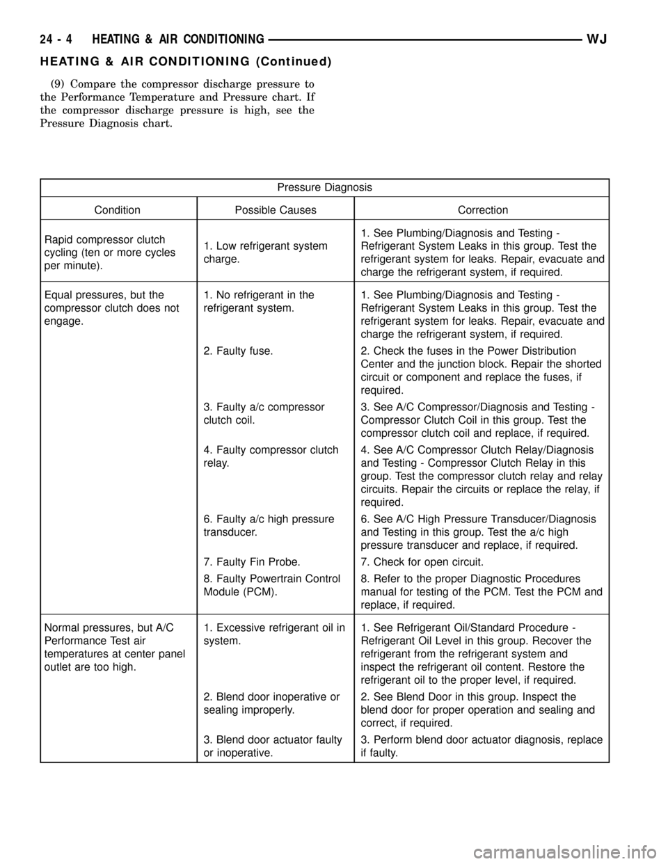
(9) Compare the compressor discharge pressure to
the Performance Temperature and Pressure chart. If
the compressor discharge pressure is high, see the
Pressure Diagnosis chart.
Pressure Diagnosis
Condition Possible Causes Correction
Rapid compressor clutch
cycling (ten or more cycles
per minute).1. Low refrigerant system
charge.1. See Plumbing/Diagnosis and Testing -
Refrigerant System Leaks in this group. Test the
refrigerant system for leaks. Repair, evacuate and
charge the refrigerant system, if required.
Equal pressures, but the
compressor clutch does not
engage.1. No refrigerant in the
refrigerant system.1. See Plumbing/Diagnosis and Testing -
Refrigerant System Leaks in this group. Test the
refrigerant system for leaks. Repair, evacuate and
charge the refrigerant system, if required.
2. Faulty fuse. 2. Check the fuses in the Power Distribution
Center and the junction block. Repair the shorted
circuit or component and replace the fuses, if
required.
3. Faulty a/c compressor
clutch coil.3. See A/C Compressor/Diagnosis and Testing -
Compressor Clutch Coil in this group. Test the
compressor clutch coil and replace, if required.
4. Faulty compressor clutch
relay.4. See A/C Compressor Clutch Relay/Diagnosis
and Testing - Compressor Clutch Relay in this
group. Test the compressor clutch relay and relay
circuits. Repair the circuits or replace the relay, if
required.
6. Faulty a/c high pressure
transducer.6. See A/C High Pressure Transducer/Diagnosis
and Testing in this group. Test the a/c high
pressure transducer and replace, if required.
7. Faulty Fin Probe. 7. Check for open circuit.
8. Faulty Powertrain Control
Module (PCM).8. Refer to the proper Diagnostic Procedures
manual for testing of the PCM. Test the PCM and
replace, if required.
Normal pressures, but A/C
Performance Test air
temperatures at center panel
outlet are too high.1. Excessive refrigerant oil in
system.1. See Refrigerant Oil/Standard Procedure -
Refrigerant Oil Level in this group. Recover the
refrigerant from the refrigerant system and
inspect the refrigerant oil content. Restore the
refrigerant oil to the proper level, if required.
2. Blend door inoperative or
sealing improperly.2. See Blend Door in this group. Inspect the
blend door for proper operation and sealing and
correct, if required.
3. Blend door actuator faulty
or inoperative.3. Perform blend door actuator diagnosis, replace
if faulty.
24 - 4 HEATING & AIR CONDITIONINGWJ
HEATING & AIR CONDITIONING (Continued)