power seat JEEP GRAND CHEROKEE 2003 WJ / 2.G User Guide
[x] Cancel search | Manufacturer: JEEP, Model Year: 2003, Model line: GRAND CHEROKEE, Model: JEEP GRAND CHEROKEE 2003 WJ / 2.GPages: 2199, PDF Size: 76.01 MB
Page 306 of 2199
CHIME/BUZZER
TABLE OF CONTENTS
page page
CHIME WARNING SYSTEM
DESCRIPTION..........................1
OPERATION............................1DIAGNOSIS AND TESTING - CHIME
WARNING SYSTEM.....................3
CHIME WARNING SYSTEM
DESCRIPTION
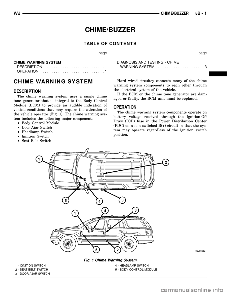
The chime warning system uses a single chime
tone generator that is integral to the Body Control
Module (BCM) to provide an audible indication of
vehicle conditions that may require the attention of
the vehicle operator (Fig. 1). The chime warning sys-
tem includes the following major components:
²Body Control Module
²Door Ajar Switch
²Headlamp Switch
²Ignition Switch
²Seat Belt SwitchHard wired circuitry connects many of the chime
warning system components to each other through
the electrical system of the vehicle.
If the BCM or the chime tone generator are dam-
aged or faulty, the BCM unit must be replaced.
OPERATION
The chime warning system components operate on
battery voltage received through the Ignition-Off
Draw (IOD) fuse in the Power Distribution Center
(PDC) on a non-switched B(+) circuit so that the sys-
tem may operate regardless of the ignition switch
position.
Fig. 1 Chime Warning System
1 - IGNITION SWITCH
2 - SEAT BELT SWITCH
3 - DOOR AJAR SWITCH4 - HEADLAMP SWITCH
5 - BODY CONTROL MODULE
WJCHIME/BUZZER 8B - 1
Page 307 of 2199
The chime warning system provides an audible
indication to the vehicle operator under the following
conditions:
²Fasten Seat Belt Warning- The Body Control
Module (BCM) chime tone generator will generate
repetitive chimes to announce that an input from the
seat belt switch indicates the driver side front seat
belt is not fastened. Unless the driver side front seat
belt is fastened, the chimes will continue to sound for
a duration of about six seconds each time the ignition
switch is turned to the On position or until the driver
side front seat belt is fastened.
²Head/Park Lights-On Warning- The BCM
chime tone generator will generate repetitive chimes
at a fast rate to announce that a Programmable
Communications Interface (PCI) data bus driver door
ajar message, along with hard wired inputs from the
headlamp switch indicate that the exterior lamps are
turned On with the driver side front door opened.
The chime will continue to sound until the exterior
lamps are turned Off, the driver side front door is
closed, or the ignition switch is turned to the On
position.
²Key-In-Ignition Warning- The BCM chime
tone generator will generate repetitive chimes at a
fast rate to announce that a PCI data bus driver door
ajar message received from the Driver Door Module
(DDM), along with hard wired inputs from the key-
in-ignition warning switch indicate that the key is in
the ignition cylinder with the driver side front door
opened and the ignition switch in the Off position.
The chime will continue to sound until the key is
removed from the ignition lock cylinder, the driver
side front door is closed, or the ignition switch is
turned to the On position.
²Overspeed Warning- The BCM chime tone
generator will generate repetitive chimes at a slowrate to announce that a PCI data bus vehicle speed
message received from the Powertrain Control Mod-
ule (PCM) indicates that the vehicle speed is above
120 kilometers-per-hour (75 miles-per-hour). The
chimes will continue to sound until the vehicle speed
is below 120 kilometers-per-hour (75 miles-per-hour).
This feature is only enabled on a BCM that has been
programmed with a Middle East Gulf Coast Country
(GCC) country code.
²Tactile Beep Support- The BCM chime tone
generator will generate a single beep each time a
PCI data bus tactile beep request message is received
from the Electronic Vehicle Information Center
(EVIC) or the Sentry Key Immobilizer Module
(SKIM). This beep provides an audible confirmation
that an EVIC button was completely depressed, or
that the optional Sentry Key Immobilizer System
(SKIS) is in the ªCustomer Learnº mode.
²Warning Beep Support- The BCM chime tone
generator will generate a short series of beeps each
time a PCI data bus warning beep request message
is received from the EVIC or the Electro-Mechanical
Instrument Cluster (EMIC). These beeps provide an
audible alert to the vehicle operator, of certain visual
warning indications displayed by the EVIC and/or
the EMIC.
The BCM provides chime service for all available
features in the chime warning system. The BCM
relies upon message inputs received from other mod-
ules over the PCI data bus network to provide chime
service for all of the remaining chime warning sys-
tem features.
The internal programming of the BCM determines
the priority of each chime tone request input that is
received, as well as the rate and duration of each
chime tone that is to be generated.
8B - 2 CHIME/BUZZERWJ
CHIME WARNING SYSTEM (Continued)
Page 310 of 2199
ELECTRONIC CONTROL MODULES
TABLE OF CONTENTS
page page
ELECTRONIC CONTROL MODULES
STANDARD PROCEDURE - PCM/SKIM
PROGRAMMING.......................1
ADJUSTABLE PEDALS MODULE
REMOVAL.............................2
INSTALLATION..........................3
BODY CONTROL MODULE
DESCRIPTION..........................3
OPERATION............................3
DIAGNOSIS AND TESTING - BODY CONTROL
MODULE.............................4
REMOVAL.............................5
INSTALLATION..........................5
COMMUNICATION
DESCRIPTION..........................6
OPERATION............................6
CONTROLLER ANTILOCK BRAKE
DESCRIPTION..........................6
OPERATION............................6
REMOVAL.............................7
INSTALLATION..........................7
DATA LINK CONNECTOR
DESCRIPTION - DATA LINK CONNECTOR.....7
OPERATION - DATA LINK CONNECTOR......7
DOOR MODULE
DESCRIPTION..........................7
OPERATION............................9
DIAGNOSIS AND TESTING - DOOR MODULE . 10
REMOVAL.............................10
INSTALLATION.........................10
MEMORY HEATED SEAT/MIRROR MODULE
DESCRIPTION.........................10OPERATION...........................11
DIAGNOSIS AND TESTING
DIAGNOSIS AND TESTING - HEATED SEAT
MODULE............................11
REMOVAL.............................11
INSTALLATION.........................12
POWERTRAIN CONTROL MODULE
DESCRIPTION
DESCRIPTION - PCM..................12
MODES OF OPERATION................12
DESCRIPTION - 5 VOLT SUPPLIES.......14
DESCRIPTION - IGNITION CIRCUIT SENSE . 14
DESCRIPTION - POWER GROUNDS......15
DESCRIPTION - SENSOR RETURN.......15
OPERATION
OPERATION - PCM....................15
OPERATION - 5 VOLT SUPPLIES.........16
OPERATION - IGNITION CIRCUIT SENSE . . . 16
REMOVAL.............................16
INSTALLATION.........................17
SENTRY KEY IMMOBILIZER MODULE
DESCRIPTION.........................17
OPERATION...........................17
REMOVAL.............................18
INSTALLATION.........................19
TRANSMISSION CONTROL MODULE
DESCRIPTION.........................19
OPERATION...........................19
STANDARD PROCEDURE
STANDARD PROCEDURE - TCM QUICK
LEARN..............................22
ELECTRONIC CONTROL
MODULES
STANDARD PROCEDURE - PCM/SKIM
PROGRAMMING
NOTE: Before replacing the PCM, be sure to check
the related component/circuit integrity for failures
not detected due to a double fault in the circuit.
Most PCM failures are caused by internal compo-
nent failures (i.e. relays and solenoids) and shorted
circuits (i.e. pull-ups, drivers, and switched cir-
cuits). These failures are difficult to detect when a
double fault has occurred and only one DTC has
been set.When a PCM (JTEC) and the SKIM are replaced
at the same time, perform the following steps in
order:
(1) Program the new PCM (JTEC).
(2) Program the new SKIM.
(3) Replace all ignition keys and program them to
the new SKIM.
PROGRAMMING THE PCM (JTEC)
The SKIS Secret Key is an ID code that is unique
to each SKIM. This code is programmed and stored
in the SKIM, the PCM, and the ignition key tran-
sponder chip(s). When replacing the PCM, it is nec-
essary to program the secret key into the new PCM
using the DRBIIItscan tool. Perform the following
steps to program the secret key into the PCM.
WJELECTRONIC CONTROL MODULES 8E - 1
Page 318 of 2199
lamp flash features), Unlock with the optional RKE
unlock, and Panic Mode functions. The optional RKE
features are programmable.
²Switch Illumination- Each door module pro-
vides control of the power window and power lock
switch illumination for the front and rear doors on
the same side of the vehicle. The DDM provides con-
trol of the power mirror switch illumination.
²Window Lockout- The DDM monitors and
transmits the status of its integral window lockout
switch to provide the power window lockout feature
and coordinate power window switch knob illumina-
tion.
The door modules are serviced only as complete
units. Many of the features in the vehicle controlled
or supported by the door modules are programmable
using either the Electronic Vehicle Information Cen-
ter (EVIC) user interface, or the DRBIIItscan tool. If
a door module is damaged or faulty, the entire door
module unit must be replaced.
OPERATION
The microprocessor-based DDM and PDM hard-
ware and software monitors integral and hard wired
external switch inputs as well as those resources it
shares with other electronic modules in the vehicle
through its communication over the PCI data bus
network. The internal programming and all of these
inputs allow the DDM or PDM microprocessor to
determine the tasks it needs to perform and their
priorities, as well as both the standard and optional
features that it should provide.
The DDM and PDM are powered by a fused bat-
tery circuit so that they can operate regardless of the
ignition switch position. The DDM and PDM cir-
cuitry is grounded to the chassis beneath the front
seat.
The DDM and PDM can be diagnosed using a
DRBIIItscan tool. Refer to the appropriate diagnos-
tic information.
HARD WIRED INPUTS
The hard wired inputs to the door modules include
the following:
²Door ajar switch sense
²Driver door key cylinder switch sense (DDM)
²Fused B(+)
²Ground
²Memory switch mux (DDM)
²Mirror horizontal position signal
²Mirror vertical position signal
²PCI bus
HARD WIRED OUTPUTS
The hard wired outputs of the door modules
include the following:
²Courtesy lamp driver
²Courtesy lamp ground
²Diagnostic out (DDM)
²Door/liftgate lock driver
²Door/liftgate unlock driver
²Door switch illumination (rear power window)
²Front window driver (down)
²Front window driver (up)
²Memory set indicator driver (DDM)
²Memory switch return (DDM)
²Mirror common driver
²Mirror heater ground
²Mirror heater 12V supply
²Rear window driver (down)
²Rear window driver (up)
²Mirror horizontal driver
²Mirror sensor ground
²Mirror vertical driver
²PCI bus
²Switch illumination driver (memory - DDM)
MESSAGING
The door modules use the following messages
received from other electronic modules over the PCI
data bus:
²Accessory Delay Control (PDM)
²Courtesy Lamp Status (BCM)
²Door Ajar Status/Rear Doors (BCM)
²Door Lock Status (DDM/PDM)
²Ignition Switch Position (BCM)
²Key-In Ignition Status (BCM)
²Programmable Features Preferences/Auto Lock/
Auto Unlock/RKE Unlock Sequence/RKE Link to
Memory (EVIC)
²Memory Recall (DDM)
²Rear Window Defogger Relay Status (BCM)
²Vehicle Speed (PCM)
The door modules provide the following messages
to other electronic modules over the PCI data bus:
²Cylinder Lock Switch Status (BCM)
²Door Ajar Status/Front Doors (BCM/DDM/PDM)
²Door Lock Status (DDM/PDM)
²Memory Recall (PDM/MHSM/MSM/Radio)
²Memory Set Switch Status (PDM/MHSM/MSM/
Radio)
²Panic Control (BCM)
²Power Window Switch Status (PDM)
²RKE Status (BCM/DDM)
²Window Lockout Switch Status (PDM)
WJELECTRONIC CONTROL MODULES 8E - 9
DOOR MODULE (Continued)
Page 319 of 2199
DIAGNOSIS AND TESTING - DOOR MODULE
WARNING: ON VEHICLES EQUIPPED WITH AIR-
BAGS, DISABLE THE AIRBAG SYSTEM BEFORE
ATTEMPTING ANY STEERING WHEEL, STEERING
COLUMN, OR INSTRUMENT PANEL COMPONENT
DIAGNOSIS OR SERVICE. DISCONNECT AND ISO-
LATE THE BATTERY NEGATIVE (GROUND) CABLE,
THEN WAIT TWO MINUTES FOR THE AIRBAG SYS-
TEM CAPACITOR TO DISCHARGE BEFORE PER-
FORMING FURTHER DIAGNOSIS OR SERVICE. THIS
IS THE ONLY SURE WAY TO DISABLE THE AIRBAG
SYSTEM. FAILURE TO TAKE THE PROPER PRE-
CAUTIONS COULD RESULT IN ACCIDENTAL AIR-
BAG DEPLOYMENT AND POSSIBLE PERSONAL
INJURY.
The hard wired inputs to and outputs from the
Driver Door Module (DDM) or the Passenger Door
Module (PDM) may be diagnosed and tested using
conventional diagnostic tools and procedures. It is
suggested that the proper operation of the inopera-
tive power window motor, power door lock motor,
power liftgate lock motor, power mirror motors, or
heated mirror grid be confirmed using jumper wires
to bypass the door module. If the inoperative compo-
nent operates when the door module is bypassed,
check the circuits between the component and the
door module, as well as the fused B(+) and ground
circuits of the door module for shorts or opens.
These conventional diagnostic methods may not
prove conclusive in the diagnosis of the DDM or the
PDM. In order to obtain conclusive testing of these
modules, the Programmable Communications Inter-
face (PCI) data bus network and all of the modules
that provide inputs to or receive outputs from the
door modules must also be checked. The most reli-
able, efficient, and accurate means to diagnose the
DDM, the PDM, the PCI data bus network, and the
modules that provide inputs to or receive outputs
from the door modules requires the use of a DRBIIIt
scan tool and the appropriate diagnostic information.
REMOVAL
(1) Disconnect and isolate the battery negative
cable.
(2) Remove the trim panel from the front door.
(Refer to 23 - BODY/DOOR - FRONT/TRIM PANEL -
REMOVAL).
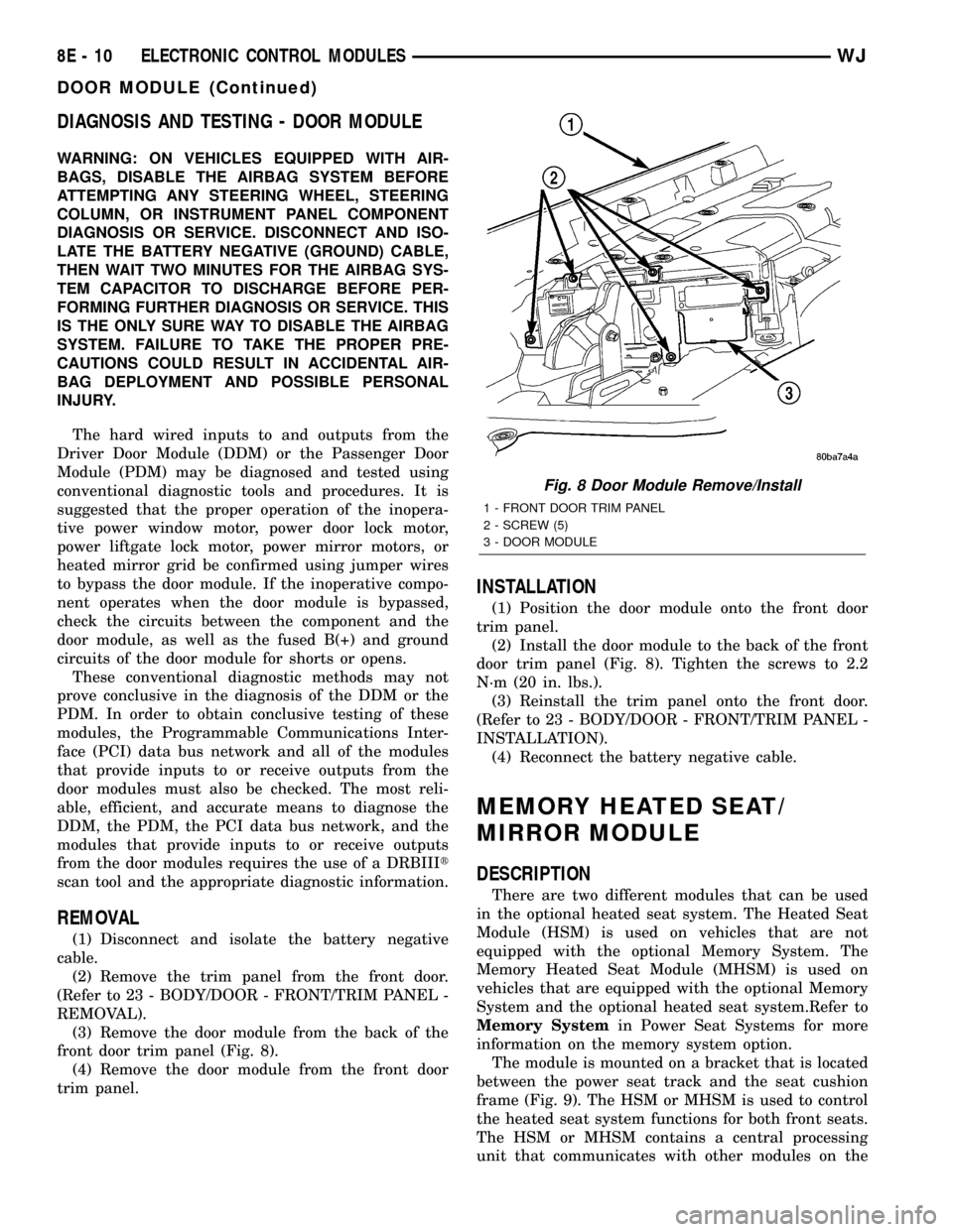
(3) Remove the door module from the back of the
front door trim panel (Fig. 8).
(4) Remove the door module from the front door
trim panel.
INSTALLATION
(1) Position the door module onto the front door
trim panel.
(2) Install the door module to the back of the front
door trim panel (Fig. 8). Tighten the screws to 2.2
N´m (20 in. lbs.).
(3) Reinstall the trim panel onto the front door.
(Refer to 23 - BODY/DOOR - FRONT/TRIM PANEL -
INSTALLATION).
(4) Reconnect the battery negative cable.
MEMORY HEATED SEAT/
MIRROR MODULE
DESCRIPTION
There are two different modules that can be used
in the optional heated seat system. The Heated Seat
Module (HSM) is used on vehicles that are not
equipped with the optional Memory System. The
Memory Heated Seat Module (MHSM) is used on
vehicles that are equipped with the optional Memory
System and the optional heated seat system.Refer to
Memory Systemin Power Seat Systems for more
information on the memory system option.
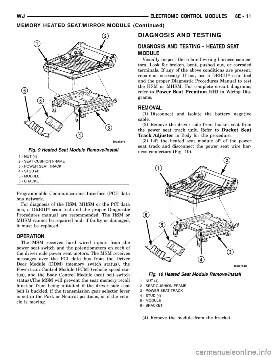
The module is mounted on a bracket that is located
between the power seat track and the seat cushion
frame (Fig. 9). The HSM or MHSM is used to control
the heated seat system functions for both front seats.
The HSM or MHSM contains a central processing
unit that communicates with other modules on the
Fig. 8 Door Module Remove/Install
1 - FRONT DOOR TRIM PANEL
2 - SCREW (5)
3 - DOOR MODULE
8E - 10 ELECTRONIC CONTROL MODULESWJ
DOOR MODULE (Continued)
Page 320 of 2199
Programmable Communications Interface (PCI) data
bus network.
For diagnosis of the HSM, MHSM or the PCI data
bus, a DRBIIItscan tool and the proper Diagnostic
Procedures manual are recommended. The HSM or
MHSM cannot be repaired and, if faulty or damaged,
it must be replaced.
OPERATION
The MSM receives hard wired inputs from the
power seat switch and the potentiometers on each of
the driver side power seat motors. The MSM receives
messages over the PCI data bus from the Driver
Door Module (DDM) (memory switch status), the
Powertrain Control Module (PCM) (vehicle speed sta-
tus), and the Body Control Module (seat belt switch
status).The MSM will prevent the seat memory recall
function from being initiated if the driver side seat
belt is buckled, if the transmission gear selector lever
is not in the Park or Neutral positions, or if the vehi-
cle is moving.
DIAGNOSIS AND TESTING
DIAGNOSIS AND TESTING - HEATED SEAT
MODULE
Visually inspect the related wiring harness connec-
tors. Look for broken, bent, pushed out, or corroded
terminals. If any of the above conditions are present,
repair as necessary. If not, use a DRBIIItscan tool
and the proper Diagnostic Procedures Manual to test
the HSM or MHSM. For complete circuit diagrams,
refer toPower Seat Premium I/IIIin Wiring Dia-
grams.
REMOVAL
(1) Disconnect and isolate the battery negative
cable.
(2) Remove the driver side front bucket seat from
the power seat track unit. Refer toBucket Seat
Track Adjusterin Body for the procedure.
(3) Lift the heated seat module off of the power
seat track and disconnect the power seat wire har-
ness connectors (Fig. 10).
(4) Remove the module from the bracket.
Fig. 9 Heated Seat Module Remove/Install
1 - NUT (4)
2 - SEAT CUSHION FRAME
3 - POWER SEAT TRACK
4 - STUD (4)
5 - MODULE
6 - BRACKET
Fig. 10 Heated Seat Module Remove/Install
1 - NUT (4)
2 - SEAT CUSHION FRAME
3 - POWER SEAT TRACK
4 - STUD (4)
5 - MODULE
6 - BRACKET
WJELECTRONIC CONTROL MODULES 8E - 11
MEMORY HEATED SEAT/MIRROR MODULE (Continued)
Page 321 of 2199
INSTALLATION
(1) Install the MHSM,HSM into the bracket.
(2) Position the heated seat module and mounting
bracket onto the power seat track.
(3) Reconnect the power seat wiring harness con-
nectors to the heated seat module.
(4) Install the driver side front bucket seat onto
the power seat track unit (Refer to 23 - BODY/
SEATS/SEAT TRACK ADJUSTER - INSTALLA-
TION).
(5) Reconnect the battery negative cable.
NOTE: If the vehicle is equipped with the optional
Memory System, following installation, it will be
necessary to initialize the Memory Heated Seat
Module (MHSM). In order to function properly, the
MHSM must ªlearnº the sensor values of each of
the power seat motor position transducers in each
of the adjuster hard stop positions. This is done by
performing the ªReset Guard Bandº procedure
using a DRBIIITscan tool and the proper Diagnostic
Procedures manual.
WARNING: THE ªRESET GUARD BANDº PROCE-
DURE WILL CAUSE THE DRIVER SIDE FRONT
SEAT TO AUTOMATICALLY ADJUST TO EACH OF
ITS TRAVEL LIMITS. BE CERTAIN THAT NO ONE IS
SEATED IN THE VEHICLE AND THAT THERE IS
NOTHING IN THE VEHICLE THAT WILL OBSTRUCT
SEAT MOVEMENT. FAILURE TO OBSERVE THIS
WARNING COULD RESULT IN PERSONAL INJURIES
AND/OR VEHICLE DAMAGE.
POWERTRAIN CONTROL
MODULE
DESCRIPTION
DESCRIPTION - PCM
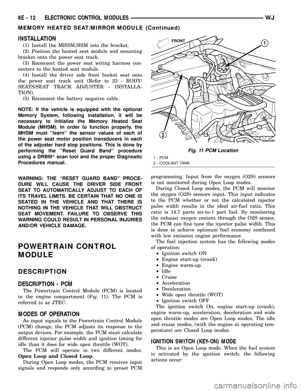
The Powertrain Control Module (PCM) is located
in the engine compartment (Fig. 11). The PCM is
referred to as JTEC.
MODES OF OPERATION
As input signals to the Powertrain Control Module
(PCM) change, the PCM adjusts its response to the
output devices. For example, the PCM must calculate
different injector pulse width and ignition timing for
idle than it does for wide open throttle (WOT).
The PCM will operate in two different modes:
Open Loop and Closed Loop.
During Open Loop modes, the PCM receives input
signals and responds only according to preset PCMprogramming. Input from the oxygen (O2S) sensors
is not monitored during Open Loop modes.
During Closed Loop modes, the PCM will monitor
the oxygen (O2S) sensors input. This input indicates
to the PCM whether or not the calculated injector
pulse width results in the ideal air-fuel ratio. This
ratio is 14.7 parts air-to-1 part fuel. By monitoring
the exhaust oxygen content through the O2S sensor,
the PCM can fine tune the injector pulse width. This
is done to achieve optimum fuel economy combined
with low emission engine performance.
The fuel injection system has the following modes
of operation:
²Ignition switch ON
²Engine start-up (crank)
²Engine warm-up
²Idle
²Cruise
²Acceleration
²Deceleration
²Wide open throttle (WOT)
²Ignition switch OFF
The ignition switch On, engine start-up (crank),
engine warm-up, acceleration, deceleration and wide
open throttle modes are Open Loop modes. The idle
and cruise modes, (with the engine at operating tem-
perature) are Closed Loop modes.
IGNITION SWITCH (KEY-ON) MODE
This is an Open Loop mode. When the fuel system
is activated by the ignition switch, the following
actions occur:
Fig. 11 PCM Location
1 - PCM
2 - COOLANT TANK
8E - 12 ELECTRONIC CONTROL MODULESWJ
MEMORY HEATED SEAT/MIRROR MODULE (Continued)
Page 380 of 2199
HEATED SEAT SYSTEM
TABLE OF CONTENTS
page page
HEATED SEAT SYSTEM
DESCRIPTION..........................9
OPERATION...........................10
DIAGNOSIS AND TESTING - HEATED SEAT
SYSTEM............................10
DRIVER HEATED SEAT SWITCH
DESCRIPTION.........................11
OPERATION...........................11
DIAGNOSIS AND TESTING - DRIVER HEATED
SEAT SWITCH........................11
REMOVAL.............................12
INSTALLATION.........................13
HEATED SEAT ELEMENT
DESCRIPTION.........................13
OPERATION...........................13
DIAGNOSIS AND TESTING - HEATED SEAT
ELEMENT...........................14REMOVAL.............................14
INSTALLATION.........................14
HEATED SEAT SENSOR
DESCRIPTION.........................15
DIAGNOSIS AND TESTING - HEATED SEAT
SENSOR............................15
REMOVAL.............................15
PASSENGER HEATED SEAT SWITCH
DESCRIPTION.........................15
OPERATION...........................16
DIAGNOSIS AND TESTING - PASSENGER
HEATED SEAT SWITCH.................16
REMOVAL.............................17
INSTALLATION.........................17
HEATED SEAT SYSTEM
DESCRIPTION
Individually controlled driver and passenger side
electrically heated front seats are available factory-
installed optional equipment on this model, when it
is also equipped with the power seat option. The
heated seat system allows both the driver and the
front seat passenger the option to select one of two
seat heating ranges, Low or High, or to turn the indi-
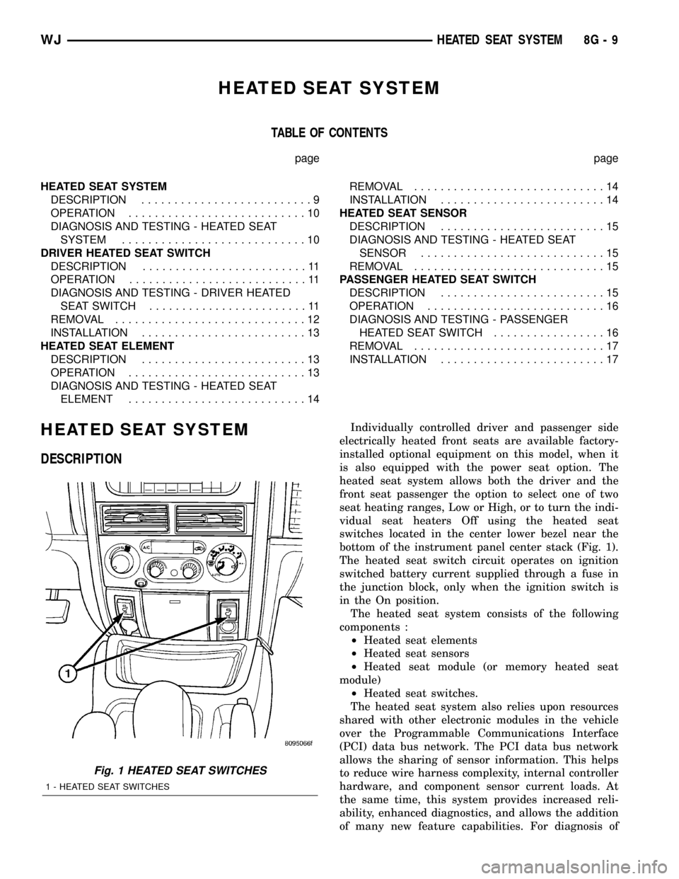
vidual seat heaters Off using the heated seat
switches located in the center lower bezel near the
bottom of the instrument panel center stack (Fig. 1).
The heated seat switch circuit operates on ignition
switched battery current supplied through a fuse in
the junction block, only when the ignition switch is
in the On position.
The heated seat system consists of the following
components :
²Heated seat elements
²Heated seat sensors
²Heated seat module (or memory heated seat
module)
²Heated seat switches.
The heated seat system also relies upon resources
shared with other electronic modules in the vehicle
over the Programmable Communications Interface
(PCI) data bus network. The PCI data bus network
allows the sharing of sensor information. This helps
to reduce wire harness complexity, internal controller
hardware, and component sensor current loads. At
the same time, this system provides increased reli-
ability, enhanced diagnostics, and allows the addition
of many new feature capabilities. For diagnosis of
Fig. 1 HEATED SEAT SWITCHES
1 - HEATED SEAT SWITCHES
WJHEATED SEAT SYSTEM 8G - 9
Page 381 of 2199
these electronic modules or of the PCI data bus net-
work, the use of a DRBtscan tool and the proper
Diagnostic Procedures manual are recommended.
The electronic modules that may affect heated seat
system operation are as follows:
²Body Control Module (BCM)- Refer toBody
Control Modulein Electronic Control Modules for
more information.
²Heated Seat Module (HSM)- Refer toHeated
Seat Modulein Electronic Control Modules for more
information.
²Memory Heated Seat Module (MHSM)-If
the vehicle is equipped with the Memory System,
refer toMemory Seat Modulein Electronic Control
Modules for more information.
Refer toPower Seats Premium I/IIIin the Con-
tents of Wiring Diagrams for complete circuit dia-
grams. Following are general descriptions of the
major components in the heated seat system.
OPERATION
The heated seat system will only operate when the
ignition switch is in the On position, and the surface
temperature at the front seat heating element sen-
sors is below the designed temperature set points of
the system. The heated seat system will not operate
in ambient temperatures greater than about 41É C
(105É F). The front seat heating elements and sensors
are hard wired to the Heated Seat Module (HSM) or
the Memory Heated Seat Module (MHSM).
The heated seat switches are hard wired to the
Body Control Module (BCM). The BCM monitors the
heated seat switch inputs, then sends heated seat
switch status messages to the HSM or MHSM over
the Programmable Communications Interface (PCI)
data bus. The HSM or MHSM contains the control
logic for the heated seat system. The HSM or MHSM
responds to the heated seat switch status messages,
ignition switch status messages, and the front seat
heating element sensor inputs by controlling the out-
put to the front seat heating elements through inte-
gral solid-state relays.
When a seat heater is turned on, the sensor
located on the seat cushion electric heater element
provides the HSM or MHSM with an input indicating
the surface temperature of the seat cushion. If the
surface temperature input is below the temperature
set point for the selected Low or High heated seat
switch position, the HSM or MHSM energizes the
integral solid-state relay, which supplies battery cur-
rent to the heating elements in the seat cushion and
back. When the sensor input indicates the correct
temperature set point has been achieved, the HSM or
MHSM de-energizes the solid-state relay. The HSM
or MHSM will continue to cycle the solid-state relay
as needed to maintain the temperature set point.The HSM or MHSM and the seat heater elements
operate on non-switched battery current supplied
through the power seat circuit breaker in the junc-
tion block. However, the HSM or MHSM will auto-
matically turn off the heating elements if it detects
an open or short in the sensor circuit, a short or open
in the heating element circuit causing an excessive
current draw, or when the ignition switch is turned
to the Off position.
See the owner's manual in the vehicle glove box for
more information on the features, use and operation
of the heated seat system.
DIAGNOSIS AND TESTING - HEATED SEAT
SYSTEM
Following are tests that will help to diagnose the
components and circuits that are hard wired inputs
or outputs of the heated seat system. However, these
tests may not prove conclusive in the diagnosis of
this system. In order to obtain conclusive testing of
the heated seat system, the Programmable Commu-
nications Interface (PCI) data bus network and all of
the electronic modules that provide inputs to, or
receive outputs from the heated seat system compo-
nents must be checked.
The most reliable, efficient, and accurate means to
diagnose the heated seat system requires the use of a
DRB scan tool and the proper Diagnostic Procedures
manual. The DRBtscan tool can provide confirma-
tion that the PCI data bus is functional, that all of
the electronic modules are sending and receiving the
proper messages on the PCI data bus, and that the
Heated Seat Module (HSM) or Memory Heated Seat
Module (MHSM) is receiving the proper hard wired
inputs and relaying the proper hard wired outputs to
perform its heated seat system functions.
For complete circuit diagrams, refer toWiring
Diagrams.
NOTE: DO NOT ATTEMPT TO SWAP MEMORY OR
NON-MEMORY HEATED SEAT MODULES FROM
ONE VEHICLE TO ANOTHER. MOST OF THESE
MODULES ARE VEHICLE FEATURE SPECIFIC AND
THEREFORE NOT INTERCHANGEABLE. ALWAYS
USE THE CORRECT PART NUMBERED MODULE
WHEN DIAGNOSING OR REPLACING A MODULE.
WARNING: REFER TO THE RESTRAINTS SECTION
OF THIS MANUAL BEFORE ATTEMPTING ANY
STEERING WHEEL, STEERING COLUMN, OR
INSTRUMENT PANEL COMPONENT DIAGNOSIS OR
SERVICE. FAILURE TO TAKE THE PROPER PRE-
CAUTIONS COULD RESULT IN ACCIDENTAL AIR-
BAG DEPLOYMENT AND POSSIBLE PERSONAL
INJURY.
8G - 10 HEATED SEAT SYSTEMWJ
HEATED SEAT SYSTEM (Continued)
Page 382 of 2199
PRELIMINARY TEST
Before testing the individual components in the
heated seat system, check the following:
²If the heated seat switch LED indicators do not
light with the ignition switch in the On position and
the heated seat switch in the Low or High position,
check the fused ignition switch output (run) fuse in
the junction block. If OK, refer toHeated Seat
Switch Diagnosis and Testingin this section. If
not OK, repair the shorted circuit or component as
required and replace the faulty fuse.
²If the heated seat switch LED indicators light,
but the heating elements do not heat, check the
power seat circuit breaker in the junction block. If
OK, refer toHeated Seat Element Diagnosis and
Testingin this section of the manual. If not OK,
replace the faulty power seat circuit breaker.
DRIVER HEATED SEAT
SWITCH
DESCRIPTION
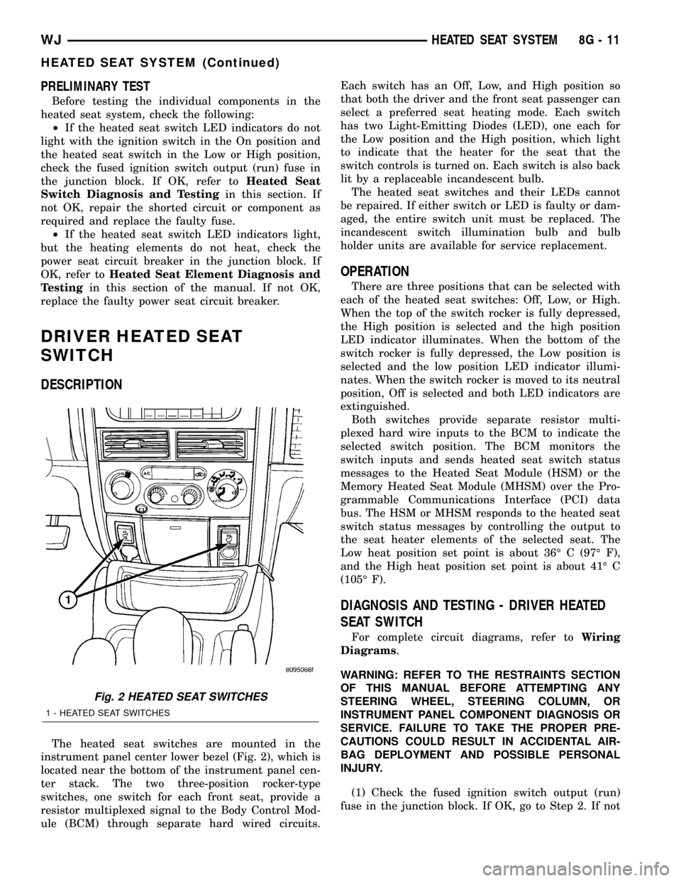
The heated seat switches are mounted in the
instrument panel center lower bezel (Fig. 2), which is
located near the bottom of the instrument panel cen-
ter stack. The two three-position rocker-type
switches, one switch for each front seat, provide a
resistor multiplexed signal to the Body Control Mod-
ule (BCM) through separate hard wired circuits.Each switch has an Off, Low, and High position so
that both the driver and the front seat passenger can
select a preferred seat heating mode. Each switch
has two Light-Emitting Diodes (LED), one each for
the Low position and the High position, which light
to indicate that the heater for the seat that the
switch controls is turned on. Each switch is also back
lit by a replaceable incandescent bulb.
The heated seat switches and their LEDs cannot
be repaired. If either switch or LED is faulty or dam-
aged, the entire switch unit must be replaced. The
incandescent switch illumination bulb and bulb
holder units are available for service replacement.
OPERATION
There are three positions that can be selected with
each of the heated seat switches: Off, Low, or High.
When the top of the switch rocker is fully depressed,
the High position is selected and the high position
LED indicator illuminates. When the bottom of the
switch rocker is fully depressed, the Low position is
selected and the low position LED indicator illumi-
nates. When the switch rocker is moved to its neutral
position, Off is selected and both LED indicators are
extinguished.
Both switches provide separate resistor multi-
plexed hard wire inputs to the BCM to indicate the
selected switch position. The BCM monitors the
switch inputs and sends heated seat switch status
messages to the Heated Seat Module (HSM) or the
Memory Heated Seat Module (MHSM) over the Pro-
grammable Communications Interface (PCI) data
bus. The HSM or MHSM responds to the heated seat
switch status messages by controlling the output to
the seat heater elements of the selected seat. The
Low heat position set point is about 36É C (97É F),
and the High heat position set point is about 41É C
(105É F).
DIAGNOSIS AND TESTING - DRIVER HEATED
SEAT SWITCH
For complete circuit diagrams, refer toWiring
Diagrams.
WARNING: REFER TO THE RESTRAINTS SECTION
OF THIS MANUAL BEFORE ATTEMPTING ANY
STEERING WHEEL, STEERING COLUMN, OR
INSTRUMENT PANEL COMPONENT DIAGNOSIS OR
SERVICE. FAILURE TO TAKE THE PROPER PRE-
CAUTIONS COULD RESULT IN ACCIDENTAL AIR-
BAG DEPLOYMENT AND POSSIBLE PERSONAL
INJURY.
(1) Check the fused ignition switch output (run)
fuse in the junction block. If OK, go to Step 2. If not
Fig. 2 HEATED SEAT SWITCHES
1 - HEATED SEAT SWITCHES
WJHEATED SEAT SYSTEM 8G - 11
HEATED SEAT SYSTEM (Continued)