power seat JEEP GRAND CHEROKEE 2003 WJ / 2.G Repair Manual
[x] Cancel search | Manufacturer: JEEP, Model Year: 2003, Model line: GRAND CHEROKEE, Model: JEEP GRAND CHEROKEE 2003 WJ / 2.GPages: 2199, PDF Size: 76.01 MB
Page 532 of 2199
PASSENGER SIDE FRONT AND REAR WINDOWS
INOPERATIVE
If the driver side front and rear power windows
operate, but the passenger side front and rear do not,
use a DRB scan tool and the proper Diagnostic Pro-
cedures manual to check the PCI data bus for proper
operation.
ONE WINDOW INOPERATIVE
The window glass and regulator mechanism must
be free to slide up and down for the power window
motor to function properly. If the window glass and
regulator is not free to move up and down, the motor
will overload and trip the integral circuit breaker. To
determine if the window glass and regulator are free,
disconnect the regulator plate from the glass. Then
slide the window up and down by hand.
There is an alternate method to check if the win-
dow glass and regulator mechanism is free. Position
the glass between the up and down stops. Then,
shake the glass in the door. Check that the glass can
be moved slightly from side to side, front to rear, and
up and down. Then check that the glass is not bound
tight in the tracks.
If the window glass and regulator mechanism is
free, refer toDoor Modulein Electrical, Power Win-
dows. If the glass is not free, inspect the window
glass mounting and operating hardware for damage
or improperly installed components. Refer toBodyto
check for proper installation or damage of the win-
dow glass mounting and operating hardware.
DOOR MODULE
NOTE: The following tests may not prove conclu-
sive in the diagnosis of this component. The most
reliable, efficient, and accurate means to diagnose
this component requires the use of a DRB scan tool
and the proper Diagnostic Procedures manual.
If the problem being diagnosed is a rear door win-
dow that does not operate from the rear door switch,
but does operate from the master switch on the
driver side front door, (Refer to 8 - ELECTRICAL/
POWER WINDOWS/POWER WINDOW SWITCH -
DIAGNOSIS AND TESTING). If the problem is a
passenger side front or rear window that operates
from the switch on that door, but does not operate
from the master switch on the driver side front door,
use a DRB scan tool and the proper Diagnostic Pro-
cedures manual to diagnose the circuitry of both door
modules and the PCI data bus. For complete circuit
diagrams, refer to the appropriate wiring informa-
tion. The wiring information includes wiring dia-
grams, proper wire and connector repair procedures,
details of wire harness routing and retention, connec-tor pin-out information and location views for the
various wire harness connectors, splices and grounds.
(1) Disconnect and isolate the battery negative
cable. Remove the trim panel from the front door, but
do not disconnect the door wire harness connectors
from the door module. Go to Step 2.
(2) Check the 15-way door wire harness connector
for the door module to see that it is fully seated in
the door module connector receptacle. If OK, go to
Step 3. If not OK, properly connect the 15-way door
wire harness connector for the door module to the
door module connector receptacle.
(3) Disconnect the 15-way door wire harness con-
nector from the door module connector receptacle.
Check for continuity between the ground circuit cav-
ity of the 15-way door wire harness connector for the
door module and a good ground. There should be con-
tinuity. If OK, go to Step 4. If not OK, repair the
open ground circuit to ground as required.
(4) Connect the battery negative cable. Check for
battery voltage at the fused B(+) circuit cavity of the
15-way door wire harness connector for the door
module. If OK, go to Step 5. If not OK, repair the
open fused B(+) circuit to the fuse in the Power Dis-
tribution Center (PDC) as required.
(5) If the inoperative window is on a front door, go
to Step 6. If the inoperative window is on a rear door
go to Step 9.
(6) Disconnect and isolate the battery negative
cable. Disconnect the door wire harness connector
from the inoperative power window motor wire har-
ness connector. Check for continuity between the
front window driver up circuit cavity of the 15-way
door wire harness connector for the door module and
a good ground. Repeat the check for the front window
driver down circuit. In each case there should be no
continuity. If OK, go to Step 7. If not OK, repair the
shorted front window driver up or down circuit as
required.
(7) Check for continuity between the front window
driver up circuit cavities of the 15-way door wire har-
ness connector for the door module and the door wire
harness connector for the power window motor.
Repeat the check for the front window driver down
circuit. In each case there should be continuity. If
OK, go to Step 8. If not OK, repair the open front
window driver up or down circuit as required.
(8) Reconnect the 15-way door wire harness con-
nector back into the door module connector recepta-
cle. Connect the battery negative cable. Connect the
probes of a reversible DC digital voltmeter to the
door wire harness connector for the power window
motor. Observe the voltmeter while actuating the
switch for that window in the up and down direc-
tions. There should be battery voltage for as long as
the switch is held in both the up and down positions,
WJPOWER WINDOWS 8N - 35
POWER WINDOWS (Continued)
Page 566 of 2199
WARNING: DURING AND FOLLOWING ANY SEAT
BELT SERVICE, CAREFULLY INSPECT ALL SEAT
BELTS, BUCKLES, MOUNTING HARDWARE, AND
RETRACTORS FOR PROPER INSTALLATION,
OPERATION, OR DAMAGE. REPLACE ANY BELT
THAT IS CUT, FRAYED, OR TORN. STRAIGHTEN
ANY BELT THAT IS TWISTED. TIGHTEN ANY
LOOSE FASTENERS. REPLACE ANY BELT THAT
HAS A DAMAGED OR INOPERATIVE BUCKLE OR
RETRACTOR. REPLACE ANY BELT THAT HAS A
BENT OR DAMAGED LATCH PLATE OR ANCHOR
PLATE. NEVER ATTEMPT TO REPAIR A SEAT BELT
COMPONENT. ALWAYS REPLACE DAMAGED OR
FAULTY SEAT BELT COMPONENTS WITH THE COR-
RECT, NEW AND UNUSED REPLACEMENT PARTS
LISTED IN THE MOPAR PARTS CATALOG.
(1) Move the front seat to its most forward position
for easiest access to the front seat belt buckle lower
anchor screw.
(2) Disconnect and isolate the battery negative
cable. Wait two minutes for the system capacitor to
discharge before further service.
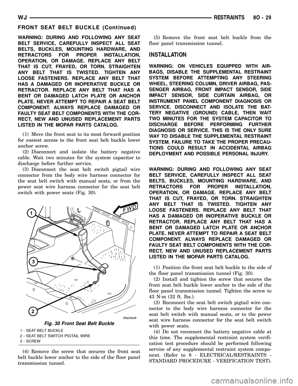
(3) Disconnect the seat belt switch pigtail wire
connector from the body wire harness connector for
the seat belt switch with manual seats, or from the
power seat wire harness connector for the seat belt
switch with power seats (Fig. 30).
(4) Remove the screw that secures the front seat
belt buckle lower anchor to the side of the floor panel
transmission tunnel.(5) Remove the front seat belt buckle from the
floor panel transmission tunnel.
INSTALLATION
WARNING: ON VEHICLES EQUIPPED WITH AIR-
BAGS, DISABLE THE SUPPLEMENTAL RESTRAINT
SYSTEM BEFORE ATTEMPTING ANY STEERING
WHEEL, STEERING COLUMN, DRIVER AIRBAG, PAS-
SENGER AIRBAG, FRONT IMPACT SENSOR, SIDE
IMPACT SENSOR, SIDE CURTAIN AIRBAG, OR
INSTRUMENT PANEL COMPONENT DIAGNOSIS OR
SERVICE. DISCONNECT AND ISOLATE THE BAT-
TERY NEGATIVE (GROUND) CABLE, THEN WAIT
TWO MINUTES FOR THE SYSTEM CAPACITOR TO
DISCHARGE BEFORE PERFORMING FURTHER
DIAGNOSIS OR SERVICE. THIS IS THE ONLY SURE
WAY TO DISABLE THE SUPPLEMENTAL RESTRAINT
SYSTEM. FAILURE TO TAKE THE PROPER PRECAU-
TIONS COULD RESULT IN ACCIDENTAL AIRBAG
DEPLOYMENT AND POSSIBLE PERSONAL INJURY.
WARNING: DURING AND FOLLOWING ANY SEAT
BELT SERVICE, CAREFULLY INSPECT ALL SEAT
BELTS, BUCKLES, MOUNTING HARDWARE, AND
RETRACTORS FOR PROPER INSTALLATION,
OPERATION, OR DAMAGE. REPLACE ANY BELT
THAT IS CUT, FRAYED, OR TORN. STRAIGHTEN
ANY BELT THAT IS TWISTED. TIGHTEN ANY
LOOSE FASTENERS. REPLACE ANY BELT THAT
HAS A DAMAGED OR INOPERATIVE BUCKLE OR
RETRACTOR. REPLACE ANY BELT THAT HAS A
BENT OR DAMAGED LATCH PLATE OR ANCHOR
PLATE. NEVER ATTEMPT TO REPAIR A SEAT BELT
COMPONENT. ALWAYS REPLACE DAMAGED OR
FAULTY SEAT BELT COMPONENTS WITH THE COR-
RECT, NEW AND UNUSED REPLACEMENT PARTS
LISTED IN THE MOPAR PARTS CATALOG.
(1) Position the front seat belt buckle to the side of
the floor panel transmission tunnel (Fig. 30).
(2) Install and tighten the screw that secures the
front seat belt buckle lower anchor to the side of the
floor panel transmission tunnel. Tighten the screw to
43 N´m (32 ft. lbs.).
(3) Reconnect the seat belt switch pigtail wire con-
nector to the body wire harness connector for the
seat belt switch with manual seats, or to the power
seat wire harness connector for the seat belt switch
with power seats.
(4) Do not reconnect the battery negative cable at
this time. The supplemental restraint system verifi-
cation test procedure should be performed following
service of any supplemental restraint system compo-
nent. (Refer to 8 - ELECTRICAL/RESTRAINTS -
STANDARD PROCEDURE - VERIFICATION TEST).
Fig. 30 Front Seat Belt Buckle
1 - SEAT BELT BUCKLE
2 - SEAT BELT SWITCH PIGTAIL WIRE
3 - SCREW
WJRESTRAINTS 8O - 29
FRONT SEAT BELT BUCKLE (Continued)
Page 574 of 2199
NOTE: Vehicles equipped with a three-point center
seat belt have the center seat belt lower anchor
secured to the right buckle anchor plate with a
screw instead of the center lap belt. (Refer to 8 -
ELECTRICAL/RESTRAINTS/REAR CENTER SEAT
BELT & RETRACTOR - INSTALLATION).
(3) Fold the rear seat cushion back into the seat-
ing position.
SEAT BELT SWITCH
DESCRIPTION
The seat belt switch for this model is actually a
Hall Effect-type sensor. This sensor consists of a
fixed-position, Hall Effect Integrated Circuit (IC) chip
and a small permanent magnet that are integral to
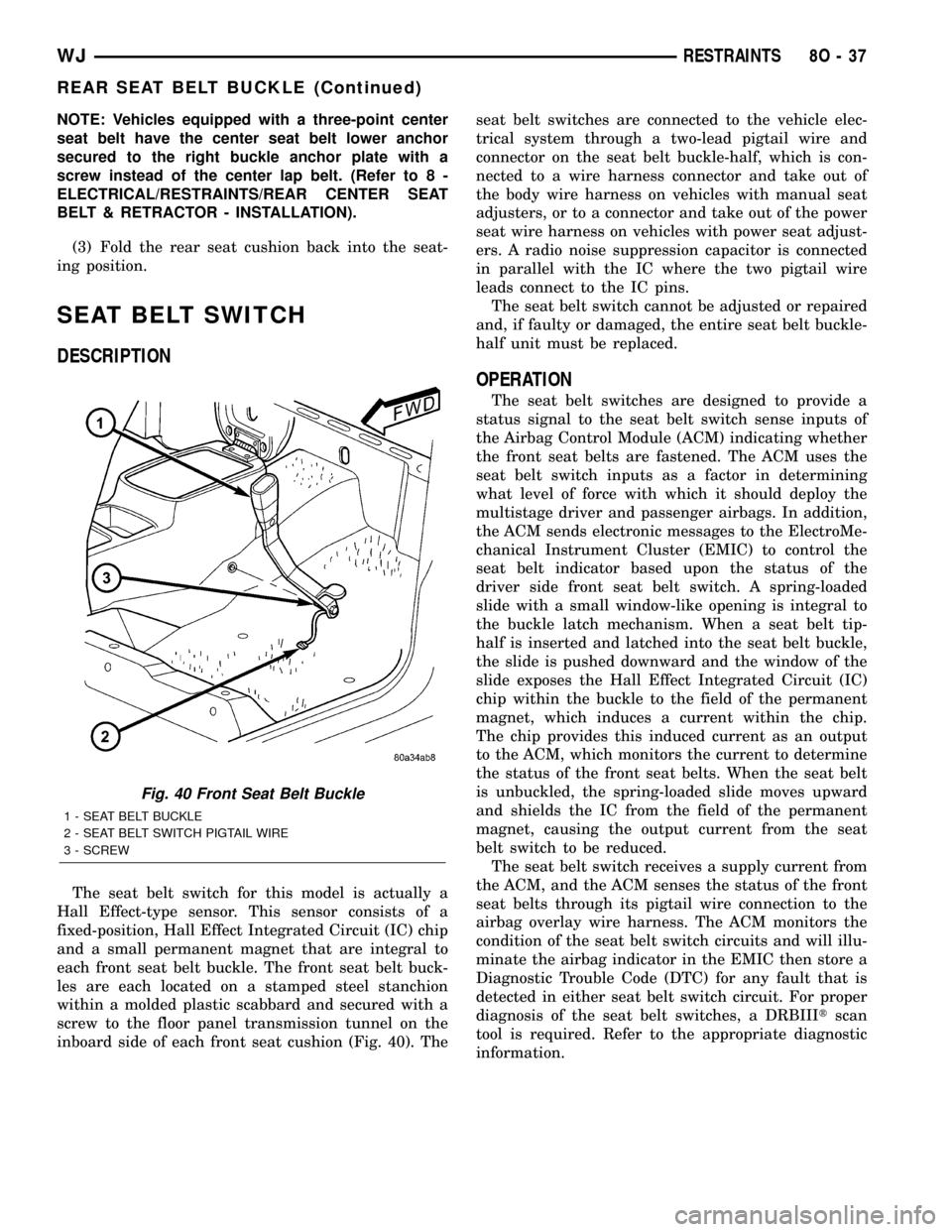
each front seat belt buckle. The front seat belt buck-
les are each located on a stamped steel stanchion
within a molded plastic scabbard and secured with a
screw to the floor panel transmission tunnel on the
inboard side of each front seat cushion (Fig. 40). Theseat belt switches are connected to the vehicle elec-
trical system through a two-lead pigtail wire and
connector on the seat belt buckle-half, which is con-
nected to a wire harness connector and take out of
the body wire harness on vehicles with manual seat
adjusters, or to a connector and take out of the power
seat wire harness on vehicles with power seat adjust-
ers. A radio noise suppression capacitor is connected
in parallel with the IC where the two pigtail wire
leads connect to the IC pins.
The seat belt switch cannot be adjusted or repaired
and, if faulty or damaged, the entire seat belt buckle-
half unit must be replaced.
OPERATION
The seat belt switches are designed to provide a
status signal to the seat belt switch sense inputs of
the Airbag Control Module (ACM) indicating whether
the front seat belts are fastened. The ACM uses the
seat belt switch inputs as a factor in determining
what level of force with which it should deploy the
multistage driver and passenger airbags. In addition,
the ACM sends electronic messages to the ElectroMe-
chanical Instrument Cluster (EMIC) to control the
seat belt indicator based upon the status of the
driver side front seat belt switch. A spring-loaded
slide with a small window-like opening is integral to
the buckle latch mechanism. When a seat belt tip-
half is inserted and latched into the seat belt buckle,
the slide is pushed downward and the window of the
slide exposes the Hall Effect Integrated Circuit (IC)
chip within the buckle to the field of the permanent
magnet, which induces a current within the chip.
The chip provides this induced current as an output
to the ACM, which monitors the current to determine
the status of the front seat belts. When the seat belt
is unbuckled, the spring-loaded slide moves upward
and shields the IC from the field of the permanent
magnet, causing the output current from the seat
belt switch to be reduced.
The seat belt switch receives a supply current from
the ACM, and the ACM senses the status of the front
seat belts through its pigtail wire connection to the
airbag overlay wire harness. The ACM monitors the
condition of the seat belt switch circuits and will illu-
minate the airbag indicator in the EMIC then store a
Diagnostic Trouble Code (DTC) for any fault that is
detected in either seat belt switch circuit. For proper
diagnosis of the seat belt switches, a DRBIIItscan
tool is required. Refer to the appropriate diagnostic
information.
Fig. 40 Front Seat Belt Buckle
1 - SEAT BELT BUCKLE
2 - SEAT BELT SWITCH PIGTAIL WIRE
3 - SCREW
WJRESTRAINTS 8O - 37
REAR SEAT BELT BUCKLE (Continued)
Page 626 of 2199
the more frequently the RSM will send wipe com-
mands to the BCM to operate the front wiper system.
The RSM operates on battery current received
through a fuse in the Junction Block (JB) on a fused
B(+) circuit. This circuit is switched by the power
accessory (sunroof) delay relay in the JB so that the
RSM will operate whenever the relay is energized by
the BCM. The RSM receives ground at all times
through a take out of the left body wire harness with
an eyelet terminal that is secured by a ground screw
to the front seat crossmember on the floor panel
under the left front seat. It is important to note that
the default condition for the wiper system is auto-
matic wipers Off; therefore, if no message is received
from the RSM by the BCM for more than about five
seconds, the automatic wipers will be disabled and
the BCM will default the front wiper system opera-
tion to the low speed continuous wipe mode.
The RSM ground and battery current inputs can be
diagnosed using conventional diagnostic tools and
methods. However, conventional diagnostic methods
may not prove conclusive in the diagnosis of the RSM
internal circuitry, the BCM, the PCI data bus net-
work, or the electronic messages received and trans-
mitted by the RSM over the PCI data bus. The most
reliable, efficient, and accurate means to diagnose
the RSM requires the use of a DRBIIItscan tool.
Refer to the appropriate diagnostic information.
REMOVAL
WARNING: ON VEHICLES EQUIPPED WITH AIR-
BAGS, DISABLE THE SUPPLEMENTAL RESTRAINT
SYSTEM BEFORE ATTEMPTING ANY STEERING
WHEEL, STEERING COLUMN, DRIVER AIRBAG,
PASSENGER AIRBAG, SIDE CURTAIN AIRBAG,
FRONT IMPACT SENSOR, SIDE IMPACT SENSOR,
OR INSTRUMENT PANEL COMPONENT DIAGNOSIS
OR SERVICE. DISCONNECT AND ISOLATE THE
BATTERY NEGATIVE (GROUND) CABLE, THEN
WAIT TWO MINUTES FOR THE SYSTEM CAPACI-
TOR TO DISCHARGE BEFORE PERFORMING FUR-
THER DIAGNOSIS OR SERVICE. THIS IS THE ONLY
SURE WAY TO DISABLE THE SUPPLEMENTAL
RESTRAINT SYSTEM. FAILURE TO TAKE THE
PROPER PRECAUTIONS COULD RESULT IN ACCI-
DENTAL AIRBAG DEPLOYMENT AND POSSIBLE
PERSONAL INJURY.
(1) Disconnect and isolate the battery negative
cable.
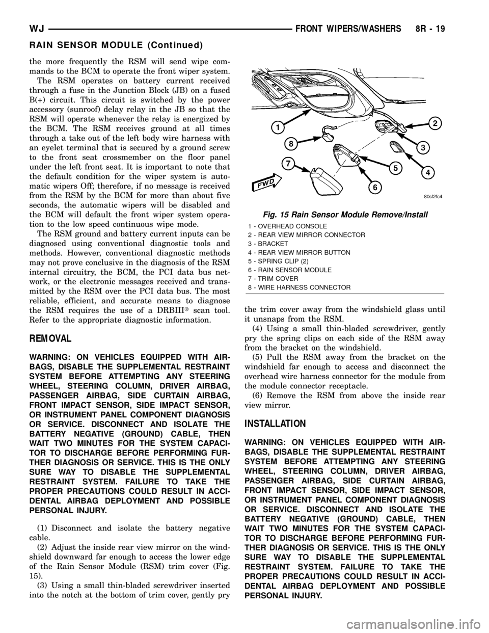
(2) Adjust the inside rear view mirror on the wind-
shield downward far enough to access the lower edge
of the Rain Sensor Module (RSM) trim cover (Fig.
15).
(3) Using a small thin-bladed screwdriver inserted
into the notch at the bottom of trim cover, gently prythe trim cover away from the windshield glass until
it unsnaps from the RSM.
(4) Using a small thin-bladed screwdriver, gently
pry the spring clips on each side of the RSM away
from the bracket on the windshield.
(5) Pull the RSM away from the bracket on the
windshield far enough to access and disconnect the
overhead wire harness connector for the module from
the module connector receptacle.
(6) Remove the RSM from above the inside rear
view mirror.
INSTALLATION
WARNING: ON VEHICLES EQUIPPED WITH AIR-
BAGS, DISABLE THE SUPPLEMENTAL RESTRAINT
SYSTEM BEFORE ATTEMPTING ANY STEERING
WHEEL, STEERING COLUMN, DRIVER AIRBAG,
PASSENGER AIRBAG, SIDE CURTAIN AIRBAG,
FRONT IMPACT SENSOR, SIDE IMPACT SENSOR,
OR INSTRUMENT PANEL COMPONENT DIAGNOSIS
OR SERVICE. DISCONNECT AND ISOLATE THE
BATTERY NEGATIVE (GROUND) CABLE, THEN
WAIT TWO MINUTES FOR THE SYSTEM CAPACI-
TOR TO DISCHARGE BEFORE PERFORMING FUR-
THER DIAGNOSIS OR SERVICE. THIS IS THE ONLY
SURE WAY TO DISABLE THE SUPPLEMENTAL
RESTRAINT SYSTEM. FAILURE TO TAKE THE
PROPER PRECAUTIONS COULD RESULT IN ACCI-
DENTAL AIRBAG DEPLOYMENT AND POSSIBLE
PERSONAL INJURY.
Fig. 15 Rain Sensor Module Remove/Install
1 - OVERHEAD CONSOLE
2 - REAR VIEW MIRROR CONNECTOR
3 - BRACKET
4 - REAR VIEW MIRROR BUTTON
5 - SPRING CLIP (2)
6 - RAIN SENSOR MODULE
7 - TRIM COVER
8 - WIRE HARNESS CONNECTOR
WJFRONT WIPERS/WASHERS 8R - 19
RAIN SENSOR MODULE (Continued)
Page 638 of 2199
(2) Position the wiper high/low relay in the proper
receptacle in the PDC.
(3) Align the wiper high/low relay terminals with
the terminal cavities in the PDC receptacle.
(4) Push firmly and evenly on the top of the wiper
high/low relay until the terminals are fully seated in
the terminal cavities in the PDC receptacle.
(5) Reinstall the cover onto the PDC.
(6) Reconnect the battery negative cable.
WIPER ON/OFF RELAY
DESCRIPTION
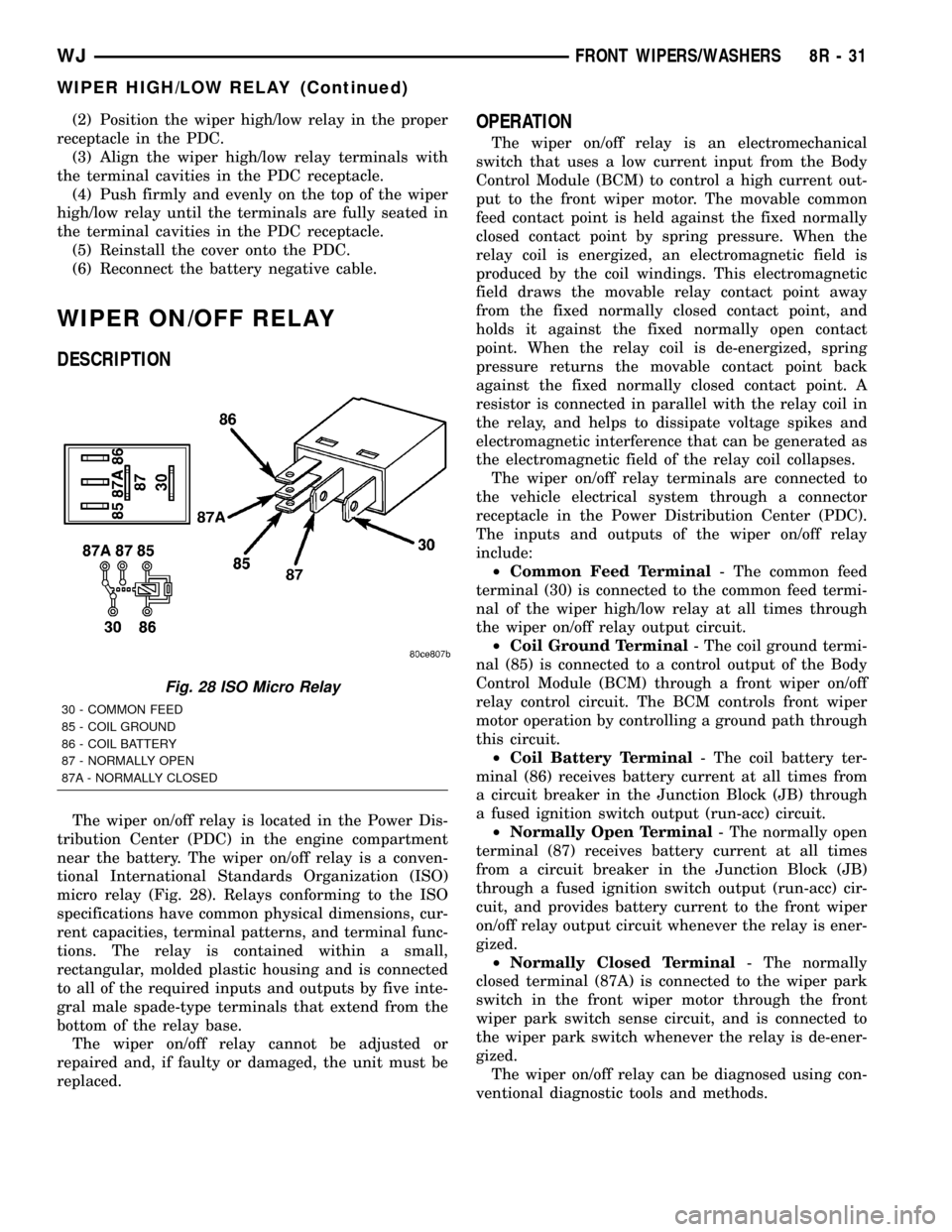
The wiper on/off relay is located in the Power Dis-
tribution Center (PDC) in the engine compartment
near the battery. The wiper on/off relay is a conven-
tional International Standards Organization (ISO)
micro relay (Fig. 28). Relays conforming to the ISO
specifications have common physical dimensions, cur-
rent capacities, terminal patterns, and terminal func-
tions. The relay is contained within a small,
rectangular, molded plastic housing and is connected
to all of the required inputs and outputs by five inte-
gral male spade-type terminals that extend from the
bottom of the relay base.
The wiper on/off relay cannot be adjusted or
repaired and, if faulty or damaged, the unit must be
replaced.
OPERATION
The wiper on/off relay is an electromechanical
switch that uses a low current input from the Body
Control Module (BCM) to control a high current out-
put to the front wiper motor. The movable common
feed contact point is held against the fixed normally
closed contact point by spring pressure. When the
relay coil is energized, an electromagnetic field is
produced by the coil windings. This electromagnetic
field draws the movable relay contact point away
from the fixed normally closed contact point, and
holds it against the fixed normally open contact
point. When the relay coil is de-energized, spring
pressure returns the movable contact point back
against the fixed normally closed contact point. A
resistor is connected in parallel with the relay coil in
the relay, and helps to dissipate voltage spikes and
electromagnetic interference that can be generated as
the electromagnetic field of the relay coil collapses.
The wiper on/off relay terminals are connected to
the vehicle electrical system through a connector
receptacle in the Power Distribution Center (PDC).
The inputs and outputs of the wiper on/off relay
include:
²Common Feed Terminal- The common feed
terminal (30) is connected to the common feed termi-
nal of the wiper high/low relay at all times through
the wiper on/off relay output circuit.
²Coil Ground Terminal- The coil ground termi-
nal (85) is connected to a control output of the Body
Control Module (BCM) through a front wiper on/off
relay control circuit. The BCM controls front wiper
motor operation by controlling a ground path through
this circuit.
²Coil Battery Terminal- The coil battery ter-
minal (86) receives battery current at all times from
a circuit breaker in the Junction Block (JB) through
a fused ignition switch output (run-acc) circuit.
²Normally Open Terminal- The normally open
terminal (87) receives battery current at all times
from a circuit breaker in the Junction Block (JB)
through a fused ignition switch output (run-acc) cir-
cuit, and provides battery current to the front wiper
on/off relay output circuit whenever the relay is ener-
gized.
²Normally Closed Terminal- The normally
closed terminal (87A) is connected to the wiper park
switch in the front wiper motor through the front
wiper park switch sense circuit, and is connected to
the wiper park switch whenever the relay is de-ener-
gized.
The wiper on/off relay can be diagnosed using con-
ventional diagnostic tools and methods.
Fig. 28 ISO Micro Relay
30 - COMMON FEED
85 - COIL GROUND
86 - COIL BATTERY
87 - NORMALLY OPEN
87A - NORMALLY CLOSED
WJFRONT WIPERS/WASHERS 8R - 31
WIPER HIGH/LOW RELAY (Continued)
Page 639 of 2199
DIAGNOSIS AND TESTING - WIPER ON/OFF
RELAY
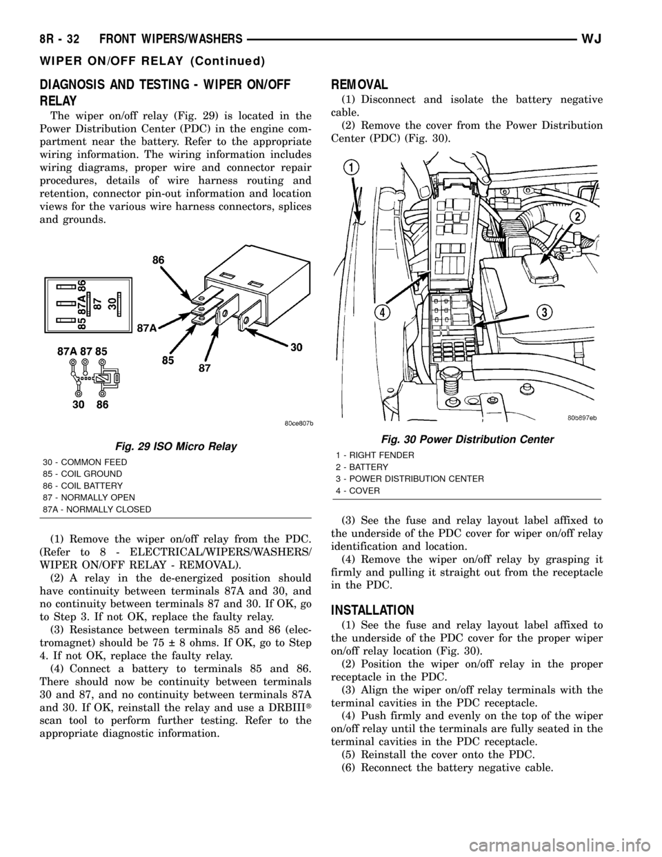
The wiper on/off relay (Fig. 29) is located in the
Power Distribution Center (PDC) in the engine com-
partment near the battery. Refer to the appropriate
wiring information. The wiring information includes
wiring diagrams, proper wire and connector repair
procedures, details of wire harness routing and
retention, connector pin-out information and location
views for the various wire harness connectors, splices
and grounds.
(1) Remove the wiper on/off relay from the PDC.
(Refer to 8 - ELECTRICAL/WIPERS/WASHERS/
WIPER ON/OFF RELAY - REMOVAL).
(2) A relay in the de-energized position should
have continuity between terminals 87A and 30, and
no continuity between terminals 87 and 30. If OK, go
to Step 3. If not OK, replace the faulty relay.
(3) Resistance between terminals 85 and 86 (elec-
tromagnet) should be 75 8 ohms. If OK, go to Step
4. If not OK, replace the faulty relay.
(4) Connect a battery to terminals 85 and 86.
There should now be continuity between terminals
30 and 87, and no continuity between terminals 87A
and 30. If OK, reinstall the relay and use a DRBIIIt
scan tool to perform further testing. Refer to the
appropriate diagnostic information.
REMOVAL
(1) Disconnect and isolate the battery negative
cable.
(2) Remove the cover from the Power Distribution
Center (PDC) (Fig. 30).
(3) See the fuse and relay layout label affixed to
the underside of the PDC cover for wiper on/off relay
identification and location.
(4) Remove the wiper on/off relay by grasping it
firmly and pulling it straight out from the receptacle
in the PDC.
INSTALLATION
(1) See the fuse and relay layout label affixed to
the underside of the PDC cover for the proper wiper
on/off relay location (Fig. 30).
(2) Position the wiper on/off relay in the proper
receptacle in the PDC.
(3) Align the wiper on/off relay terminals with the
terminal cavities in the PDC receptacle.
(4) Push firmly and evenly on the top of the wiper
on/off relay until the terminals are fully seated in the
terminal cavities in the PDC receptacle.
(5) Reinstall the cover onto the PDC.
(6) Reconnect the battery negative cable.
Fig. 29 ISO Micro Relay
30 - COMMON FEED
85 - COIL GROUND
86 - COIL BATTERY
87 - NORMALLY OPEN
87A - NORMALLY CLOSED
Fig. 30 Power Distribution Center
1 - RIGHT FENDER
2 - BATTERY
3 - POWER DISTRIBUTION CENTER
4 - COVER
8R - 32 FRONT WIPERS/WASHERSWJ
WIPER ON/OFF RELAY (Continued)
Page 654 of 2199
WIRING
TABLE OF CONTENTS
page page
WIRING DIAGRAM INFORMATION....... 8W-01-1
COMPONENT INDEX.................. 8W-02-1
POWER DISTRIBUTION............... 8W-10-1
JUNCTION BLOCK.................... 8W-12-1
GROUND DISTRIBUTION.............. 8W-15-1
BUS COMMUNICATIONS.............. 8W-18-1
CHARGING SYSTEM.................. 8W-20-1
STARTING SYSTEM.................. 8W-21-1
FUEL/IGNITION SYSTEM.............. 8W-30-1
TRANSMISSION CONTROL SYSTEM..... 8W-31-1
VEHICLE SPEED CONTROL............ 8W-33-1
ANTILOCK BRAKES................... 8W-35-1
VEHICLE THEFT SECURITY SYSTEM..... 8W-39-1
INSTRUMENT CLUSTER............... 8W-40-1
HORN/CIGAR LIGHTER/POWER OUTLET . . 8W-41-1
AIR CONDITIONING-HEATER........... 8W-42-1
AIRBAG SYSTEM.................... 8W-43-1
INTERIOR LIGHTING.................. 8W-44-1
BODY CONTROL MODULE............. 8W-45-1AUDIO SYSTEM..................... 8W-47-1
REAR WINDOW DEFOGGER............ 8W-48-1
OVERHEAD CONSOLE................. 8W-49-1
FRONT LIGHTING.................... 8W-50-1
REAR LIGHTING..................... 8W-51-1
TURN SIGNALS...................... 8W-52-1
WIPERS............................ 8W-53-1
TRAILER TOW....................... 8W-54-1
POWER WINDOWS................... 8W-60-1
POWER DOOR LOCKS................ 8W-61-1
POWER MIRRORS................... 8W-62-1
POWER SEATS...................... 8W-63-1
POWER SUNROOF................... 8W-64-1
SPLICE INFORMATION................ 8W-70-1
CONNECTOR PIN-OUT................ 8W-80-1
CONNECTOR/GROUND/SPLICE
LOCATION........................ 8W-91-1
POWER DISTRIBUTION............... 8W-97-1 WJWIRING 8W - 1
Page 663 of 2199
²Ohmmeter - Used to check the resistance
between two points of a circuit. Low or no resistance
in a circuit means good continuity.
CAUTION: Most of the electrical components used
in today's vehicles are Solid State. When checking
resistance in these circuits use a meter with a 10 -
megohm or greater impedance rating. In addition,
make sure the power is disconnected from the cir-
cuit. Circuits that are powered up by the vehicle's
electrical system can cause damage to the equip-
ment and provide false readings.
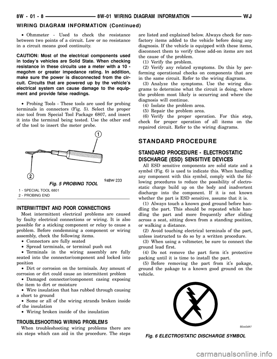
²Probing Tools - These tools are used for probing
terminals in connectors (Fig. 5). Select the proper
size tool from Special Tool Package 6807, and insert
it into the terminal being tested. Use the other end
of the tool to insert the meter probe.
INTERMITTENT AND POOR CONNECTIONS
Most intermittent electrical problems are caused
by faulty electrical connections or wiring. It is also
possible for a sticking component or relay to cause a
problem. Before condemning a component or wiring
assembly, check the following items.
²Connectors are fully seated
²Spread terminals, or terminal push out
²Terminals in the wiring assembly are fully
seated into the connector/component and locked into
position
²
Dirt or corrosion on the terminals. Any amount of
corrosion or dirt could cause an intermittent problem
²Damaged connector/component casing exposing
the item to dirt or moisture
²Wire insulation that has rubbed through causing
a short to ground
²Some or all of the wiring strands broken inside
of the insulation
²Wiring broken inside of the insulation
TROUBLESHOOTING WIRING PROBLEMS
When troubleshooting wiring problems there are
six steps which can aid in the procedure. The stepsare listed and explained below. Always check for non-
factory items added to the vehicle before doing any
diagnosis. If the vehicle is equipped with these items,
disconnect them to verify these add-on items are not
the cause of the problem.
(1) Verify the problem.
(2) Verify any related symptoms. Do this by per-
forming operational checks on components that are
in the same circuit. Refer to the wiring diagrams.
(3) Analyze the symptoms. Use the wiring dia-
grams to determine what the circuit is doing, where
the problem most likely is occurring and where the
diagnosis will continue.
(4) Isolate the problem area.
(5) Repair the problem area.
(6) Verify the proper operation. For this step,
check for proper operation of all items on the
repaired circuit. Refer to the wiring diagrams.
STANDARD PROCEDURE
STANDARD PROCEDURE - ELECTROSTATIC
DISCHARGE (ESD) SENSITIVE DEVICES
All ESD sensitive components are solid state and a
symbol (Fig. 6) is used to indicate this. When handling
any component with this symbol, comply with the fol-
lowing procedures to reduce the possibility of electro-
static charge build up on the body and inadvertent
discharge into the component. If it is not known
whether the part is ESD sensitive, assume that it is.
(1) Always touch a known good ground before han-
dling the part. This should be repeated while han-
dling the part and more frequently after sliding
across a seat, sitting down from a standing position,
or walking a distance.
(2) Avoid touching electrical terminals of the part,
unless instructed to do so by a written procedure.
(3) When using a voltmeter, be sure to connect the
ground lead first.
(4) Do not remove the part form it's protective
packing until it is time to install the part.
(5) Before removing the part from it's pakage,
ground the pakage to a known good ground on the
vehicle.
Fig. 5 PROBING TOOL
1 - SPECIAL TOOL 6801
2 - PROBING END
Fig. 6 ELECTROSTATIC DISCHARGE SYMBOL
8W - 01 - 8 8W-01 WIRING DIAGRAM INFORMATIONWJ
WIRING DIAGRAM INFORMATION (Continued)
Page 672 of 2199
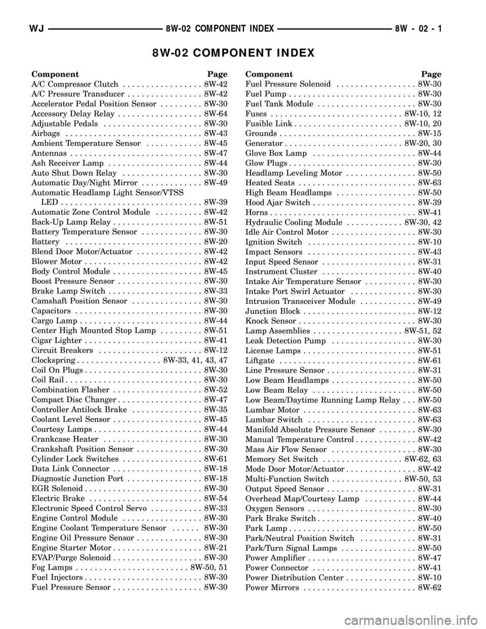
8W-02 COMPONENT INDEX
Component Page
A/C Compressor Clutch................. 8W-42
A/C Pressure Transducer................ 8W-42
Accelerator Pedal Position Sensor......... 8W-30
Accessory Delay Relay.................. 8W-64
Adjustable Pedals..................... 8W-30
Airbags............................. 8W-43
Ambient Temperature Sensor............ 8W-45
Antennas............................ 8W-47
Ash Receiver Lamp.................... 8W-44
Auto Shut Down Relay................. 8W-30
Automatic Day/Night Mirror............. 8W-49
Automatic Headlamp Light Sensor/VTSS
LED.............................. 8W-39
Automatic Zone Control Module.......... 8W-42
Back-Up Lamp Relay................... 8W-51
Battery Temperature Sensor............. 8W-30
Battery............................. 8W-20
Blend Door Motor/Actuator.............. 8W-42
Blower Motor......................... 8W-42
Body Control Module................... 8W-45
Boost Pressure Sensor.................. 8W-30
Brake Lamp Switch.................... 8W-33
Camshaft Position Sensor............... 8W-30
Capacitors........................... 8W-30
Cargo Lamp.......................... 8W-44
Center High Mounted Stop Lamp......... 8W-51
Cigar Lighter......................... 8W-41
Circuit Breakers...................... 8W-12
Clockspring.................. 8W-33, 41, 43, 47
Coil On Plugs......................... 8W-30
Coil Rail............................. 8W-30
Combination Flasher................... 8W-52
Compact Disc Changer.................. 8W-47
Controller Antilock Brake............... 8W-35
Coolant Level Sensor................... 8W-45
Courtesy Lamps....................... 8W-44
Crankcase Heater..................... 8W-30
Crankshaft Position Sensor.............. 8W-30
Cylinder Lock Switches................. 8W-61
Data Link Connector................... 8W-18
Diagnostic Junction Port................ 8W-18
EGR Solenoid......................... 8W-30
Electric Brake........................ 8W-54
Electronic Speed Control Servo........... 8W-33
Engine Control Module................. 8W-30
Engine Coolant Temperature Sensor...... 8W-30
Engine Oil Pressure Sensor.............. 8W-30
Engine Starter Motor................... 8W-21
EVAP/Purge Solenoid................... 8W-30
Fog Lamps........................ 8W-50, 51
Fuel Injectors......................... 8W-30
Fuel Pressure Sensor................... 8W-30Component Page
Fuel Pressure Solenoid................. 8W-30
Fuel Pump........................... 8W-30
Fuel Tank Module..................... 8W-30
Fuses............................ 8W-10, 12
Fusible Link....................... 8W-10, 20
Grounds............................. 8W-15
Generator......................... 8W-20, 30
Glove Box Lamp...................... 8W-44
Glow Plugs........................... 8W-30
Headlamp Leveling Motor............... 8W-50
Heated Seats......................... 8W-63
High Beam Headlamps................. 8W-50
Hood Ajar Switch...................... 8W-39
Horns............................... 8W-41
Hydraulic Cooling Module............ 8W-30, 42
Idle Air Control Motor.................. 8W-30
Ignition Switch....................... 8W-10
Impact Sensors....................... 8W-43
Input Speed Sensor.................... 8W-31
Instrument Cluster.................... 8W-40
Intake Air Temperature Sensor........... 8W-30
Intake Port Swirl Actuator.............. 8W-30
Intrusion Transceiver Module............ 8W-49
Junction Block........................ 8W-12
Knock Sensor......................... 8W-30
Lamp Assemblies................... 8W-51, 52
Leak Detection Pump.................. 8W-30
License Lamps........................ 8W-51
Liftgate............................. 8W-61
Line Pressure Sensor................... 8W-31
Low Beam Headlamps.................. 8W-50
Low Beam Relay...................... 8W-50
Low Beam/Daytime Running Lamp Relay . . . 8W-50
Lumbar Motor........................ 8W-63
Lumbar Switch....................... 8W-63
Manifold Absolute Pressure Sensor........ 8W-30
Manual Temperature Control............. 8W-42
Mass Air Flow Sensor.................. 8W-30
Memory Set Switch................. 8W-62, 63
Mode Door Motor/Actuator............... 8W-42
Multi-Function Switch............... 8W-50, 53
Output Speed Sensor................... 8W-31
Overhead Map/Courtesy Lamp........... 8W-44
Oxygen Sensors....................... 8W-30
Park Brake Switch..................... 8W-40
Park Lamp........................... 8W-50
Park/Neutral Position Switch............ 8W-31
Park/Turn Signal Lamps................ 8W-50
Power Amplifier....................... 8W-47
Power Connector...................... 8W-41
Power Distribution Center............... 8W-10
Power Mirrors........................ 8W-62
WJ8W-02 COMPONENT INDEX 8W - 02 - 1
Page 673 of 2199
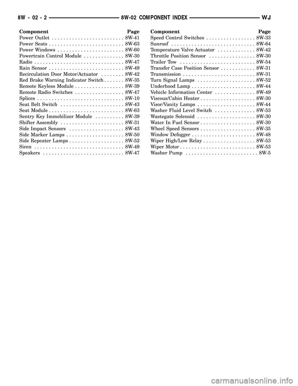
Component Page
Power Outlet......................... 8W-41
Power Seats.......................... 8W-63
Power Windows....................... 8W-60
Powertrain Control Module.............. 8W-30
Radio............................... 8W-47
Rain Sensor.......................... 8W-49
Recirculation Door Motor/Actuator........ 8W-42
Red Brake Warning Indicator Switch....... 8W-35
Remote Keyless Module................. 8W-39
Remote Radio Switches................. 8W-47
Splices.............................. 8W-10
Seat Belt Switch...................... 8W-43
Seat Module.......................... 8W-63
Sentry Key Immobilizer Module.......... 8W-39
Shifter Assembly...................... 8W-31
Side Impact Sensors................... 8W-43
Side Marker Lamps.................... 8W-50
Side Repeater Lamps................... 8W-52
Siren............................... 8W-49
Speakers............................ 8W-47Component Page
Speed Control Switches................. 8W-33
Sunroof............................. 8W-64
Temperature Valve Actuator............. 8W-42
Throttle Position Sensor................ 8W-30
Trailer Tow.......................... 8W-54
Transfer Case Position Sensor............ 8W-31
Transmission......................... 8W-31
Turn Signal Lamps.................... 8W-52
Underhood Lamp...................... 8W-44
Vehicle Information Center.............. 8W-49
Viscous/Cabin Heater................... 8W-30
Visor/Vanity Lamps.................... 8W-44
Washer Fluid Level Switch.............. 8W-53
Wastegate Solenoid.................... 8W-30
Water In Fuel Sensor................... 8W-30
Wheel Speed Sensors................... 8W-35
Window Defogger...................... 8W-48
Wiper High/Low Relay.................. 8W-53
Wiper Motor.......................... 8W-53
Washer Pump......................... 8W-5
8W - 02 - 2 8W-02 COMPONENT INDEXWJ