wheel JEEP GRAND CHEROKEE 2003 WJ / 2.G User Guide
[x] Cancel search | Manufacturer: JEEP, Model Year: 2003, Model line: GRAND CHEROKEE, Model: JEEP GRAND CHEROKEE 2003 WJ / 2.GPages: 2199, PDF Size: 76.01 MB
Page 26 of 2199
NOTE: Make sure the toe setting does not change
during clamp tightening.
(6) Verify alignment specifications, then turn the
engine off.
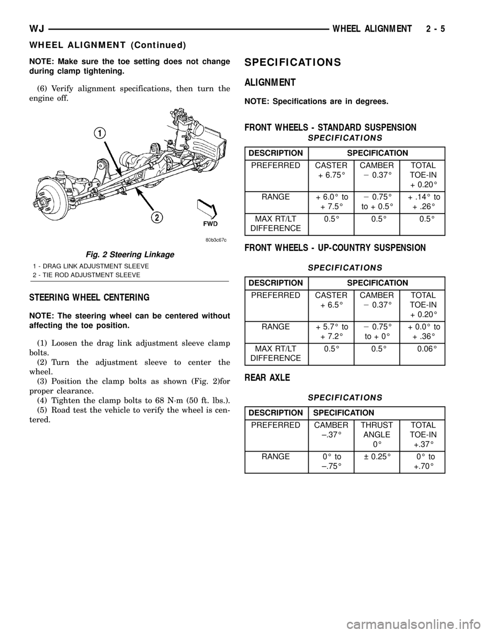
STEERING WHEEL CENTERING
NOTE: The steering wheel can be centered without
affecting the toe position.
(1) Loosen the drag link adjustment sleeve clamp
bolts.
(2) Turn the adjustment sleeve to center the
wheel.
(3) Position the clamp bolts as shown (Fig. 2)for
proper clearance.
(4) Tighten the clamp bolts to 68 N´m (50 ft. lbs.).
(5) Road test the vehicle to verify the wheel is cen-
tered.
SPECIFICATIONS
ALIGNMENT
NOTE: Specifications are in degrees.
FRONT WHEELS - STANDARD SUSPENSION
SPECIFICATIONS
DESCRIPTION SPECIFICATION
PREFERRED CASTER
+ 6.75ÉCAMBER
20.37ÉTOTAL
TOE-IN
+ 0.20É
RANGE + 6.0É to
+ 7.5É20.75É
to + 0.5É+ .14É to
+ .26É
MAX RT/LT
DIFFERENCE0.5É 0.5É 0.5É
FRONT WHEELS - UP-COUNTRY SUSPENSION
SPECIFICATIONS
DESCRIPTION SPECIFICATION
PREFERRED CASTER
+ 6.5ÉCAMBER
20.37ÉTOTAL
TOE-IN
+ 0.20É
RANGE + 5.7É to
+ 7.2É20.75É
to+0É+ 0.0É to
+ .36É
MAX RT/LT
DIFFERENCE0.5É 0.5É 0.06É
REAR AXLE
SPECIFICATIONS
DESCRIPTION SPECIFICATION
PREFERRED CAMBER
±.37ÉTHRUST
ANGLE
0ÉTOTAL
TOE-IN
+.37É
RANGE 0É to
±.75É 0.25É 0É to
+.70É
Fig. 2 Steering Linkage
1 - DRAG LINK ADJUSTMENT SLEEVE
2 - TIE ROD ADJUSTMENT SLEEVE
WJWHEEL ALIGNMENT 2 - 5
WHEEL ALIGNMENT (Continued)
Page 30 of 2199
BUSHINGS
REMOVAL
(1) Remove the upper suspension arm from axle.
(2) Position Spacer 8279 over the axle bushing on
a 4x2 vehicle and right side on a 4x4 vehicle.
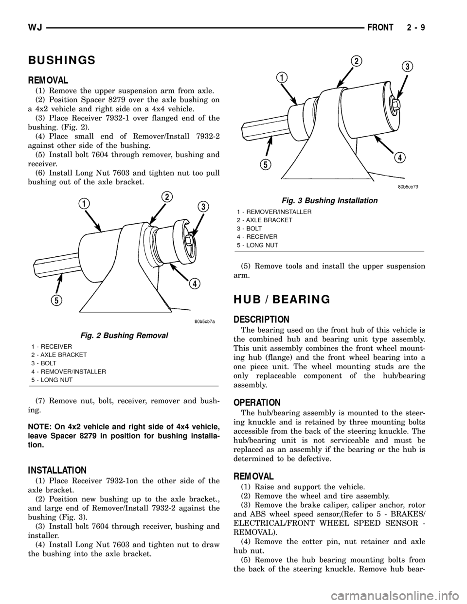
(3) Place Receiver 7932-1 over flanged end of the
bushing. (Fig. 2).
(4) Place small end of Remover/Install 7932-2
against other side of the bushing.
(5) Install bolt 7604 through remover, bushing and
receiver.
(6) Install Long Nut 7603 and tighten nut too pull
bushing out of the axle bracket.
(7) Remove nut, bolt, receiver, remover and bush-
ing.
NOTE: On 4x2 vehicle and right side of 4x4 vehicle,
leave Spacer 8279 in position for bushing installa-
tion.
INSTALLATION
(1) Place Receiver 7932-1on the other side of the
axle bracket.
(2) Position new bushing up to the axle bracket.,
and large end of Remover/Install 7932-2 against the
bushing (Fig. 3).
(3) Install bolt 7604 through receiver, bushing and
installer.
(4) Install Long Nut 7603 and tighten nut to draw
the bushing into the axle bracket.(5) Remove tools and install the upper suspension
arm.
HUB / BEARING
DESCRIPTION
The bearing used on the front hub of this vehicle is
the combined hub and bearing unit type assembly.
This unit assembly combines the front wheel mount-
ing hub (flange) and the front wheel bearing into a
one piece unit. The wheel mounting studs are the
only replaceable component of the hub/bearing
assembly.
OPERATION
The hub/bearing assembly is mounted to the steer-
ing knuckle and is retained by three mounting bolts
accessible from the back of the steering knuckle. The
hub/bearing unit is not serviceable and must be
replaced as an assembly if the bearing or the hub is
determined to be defective.
REMOVAL
(1) Raise and support the vehicle.
(2) Remove the wheel and tire assembly.
(3) Remove the brake caliper, caliper anchor, rotor
and ABS wheel speed sensor,(Refer to 5 - BRAKES/
ELECTRICAL/FRONT WHEEL SPEED SENSOR -
REMOVAL).
(4) Remove the cotter pin, nut retainer and axle
hub nut.
(5) Remove the hub bearing mounting bolts from
the back of the steering knuckle. Remove hub bear-
Fig. 2 Bushing Removal
1 - RECEIVER
2 - AXLE BRACKET
3 - BOLT
4 - REMOVER/INSTALLER
5 - LONG NUT
Fig. 3 Bushing Installation
1 - REMOVER/INSTALLER
2 - AXLE BRACKET
3 - BOLT
4 - RECEIVER
5 - LONG NUT
WJFRONT 2 - 9
Page 31 of 2199
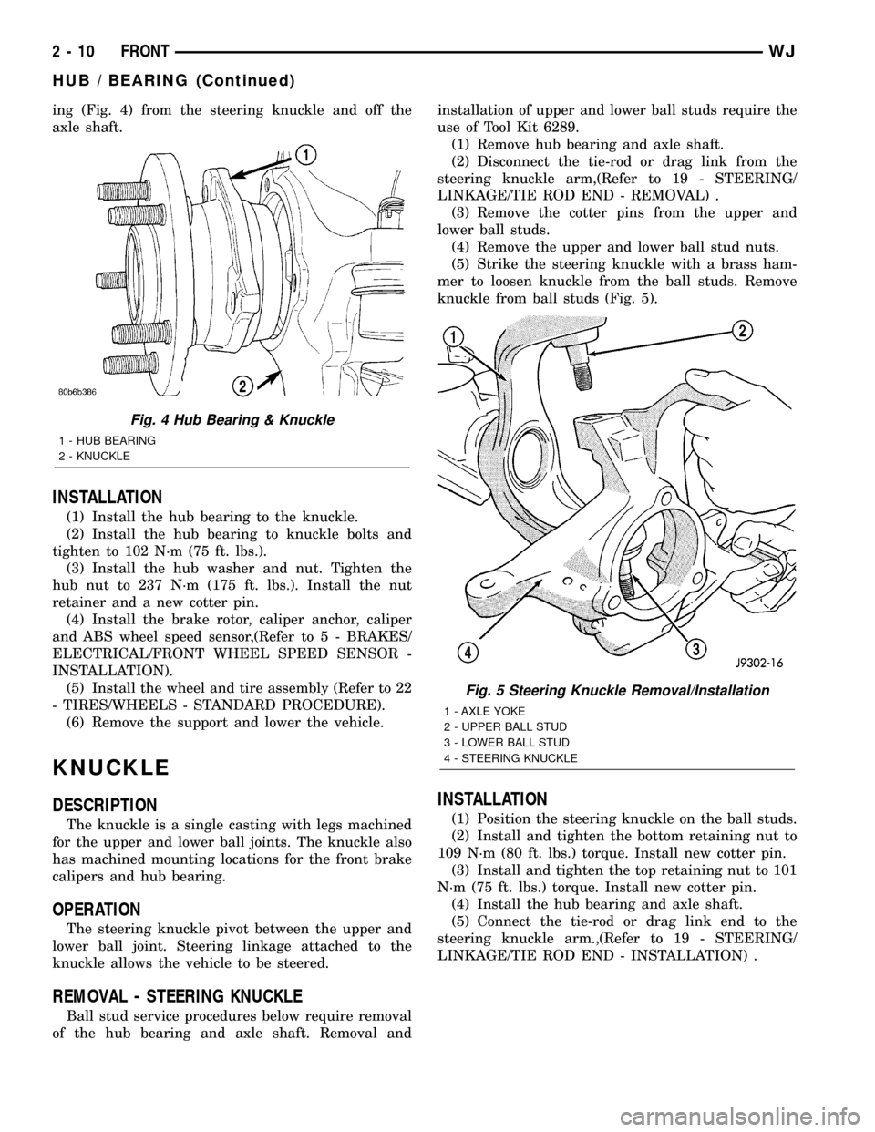
ing (Fig. 4) from the steering knuckle and off the
axle shaft.
INSTALLATION
(1) Install the hub bearing to the knuckle.
(2) Install the hub bearing to knuckle bolts and
tighten to 102 N´m (75 ft. lbs.).
(3) Install the hub washer and nut. Tighten the
hub nut to 237 N´m (175 ft. lbs.). Install the nut
retainer and a new cotter pin.
(4) Install the brake rotor, caliper anchor, caliper
and ABS wheel speed sensor,(Refer to 5 - BRAKES/
ELECTRICAL/FRONT WHEEL SPEED SENSOR -
INSTALLATION).
(5) Install the wheel and tire assembly (Refer to 22
- TIRES/WHEELS - STANDARD PROCEDURE).
(6) Remove the support and lower the vehicle.
KNUCKLE
DESCRIPTION
The knuckle is a single casting with legs machined
for the upper and lower ball joints. The knuckle also
has machined mounting locations for the front brake
calipers and hub bearing.
OPERATION
The steering knuckle pivot between the upper and
lower ball joint. Steering linkage attached to the
knuckle allows the vehicle to be steered.
REMOVAL - STEERING KNUCKLE
Ball stud service procedures below require removal
of the hub bearing and axle shaft. Removal andinstallation of upper and lower ball studs require the
use of Tool Kit 6289.
(1) Remove hub bearing and axle shaft.
(2) Disconnect the tie-rod or drag link from the
steering knuckle arm,(Refer to 19 - STEERING/
LINKAGE/TIE ROD END - REMOVAL) .
(3) Remove the cotter pins from the upper and
lower ball studs.
(4) Remove the upper and lower ball stud nuts.
(5) Strike the steering knuckle with a brass ham-
mer to loosen knuckle from the ball studs. Remove
knuckle from ball studs (Fig. 5).
INSTALLATION
(1) Position the steering knuckle on the ball studs.
(2) Install and tighten the bottom retaining nut to
109 N´m (80 ft. lbs.) torque. Install new cotter pin.
(3) Install and tighten the top retaining nut to 101
N´m (75 ft. lbs.) torque. Install new cotter pin.
(4) Install the hub bearing and axle shaft.
(5) Connect the tie-rod or drag link end to the
steering knuckle arm.,(Refer to 19 - STEERING/
LINKAGE/TIE ROD END - INSTALLATION) .
Fig. 4 Hub Bearing & Knuckle
1 - HUB BEARING
2 - KNUCKLE
Fig. 5 Steering Knuckle Removal/Installation
1 - AXLE YOKE
2 - UPPER BALL STUD
3 - LOWER BALL STUD
4 - STEERING KNUCKLE
2 - 10 FRONTWJ
HUB / BEARING (Continued)
Page 33 of 2199
SHOCK
DESCRIPTION
The top of the shock absorbers are bolted to the
body. The bottom of the shocks are bolted to the axle
brackets. The standard shocks have conventional
twin tube construction and are low pressure gas
charged. Gas charging prevents cavitation during
rough road operation. Up-Country shocks are mono
tube design and are high pressure gas charged.
OPERATION
The shock absorbers dampen jounce and rebound
motion of the vehicle over various road conditions
and limit suspension rebound travel.
REMOVAL
(1) Remove the nut, retainer and grommet from
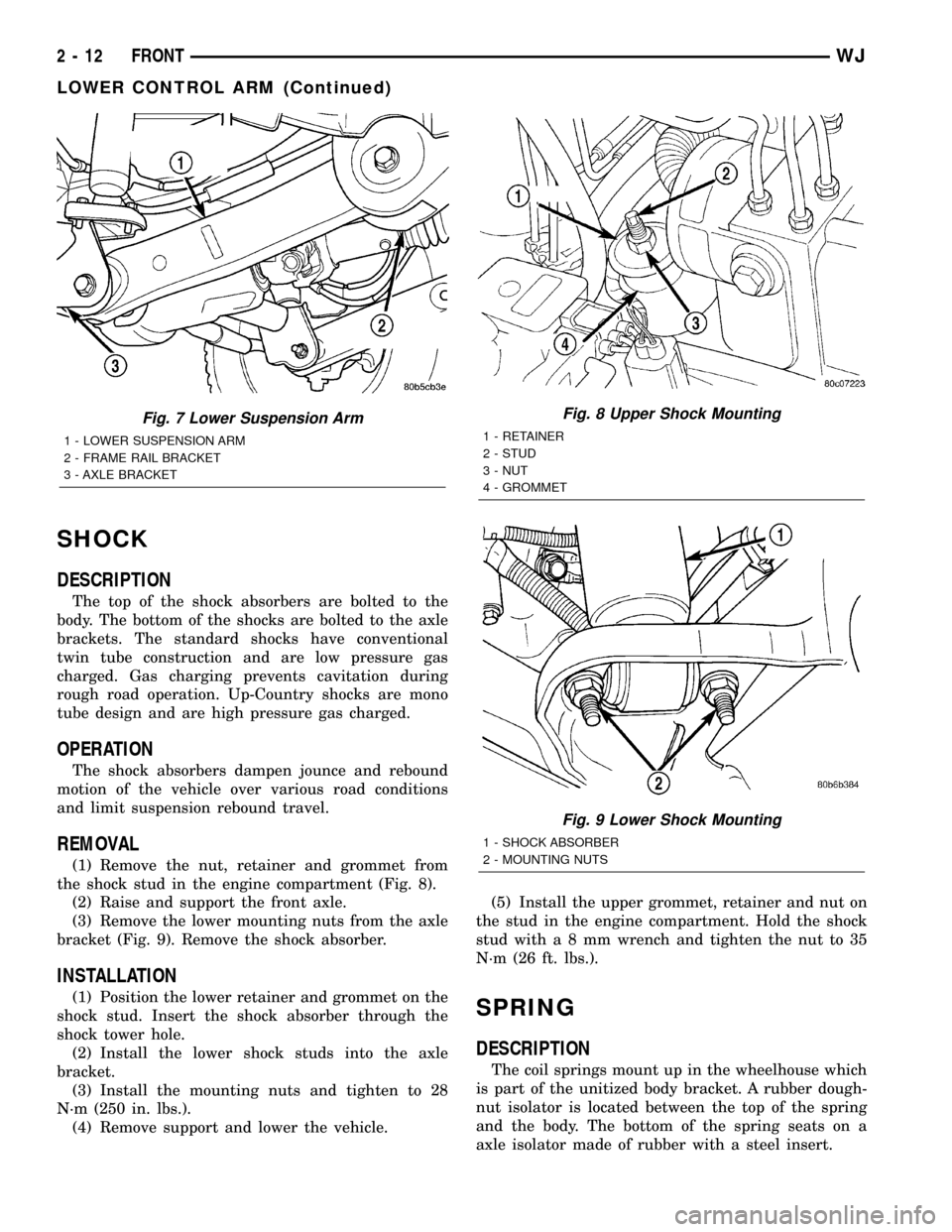
the shock stud in the engine compartment (Fig. 8).
(2) Raise and support the front axle.
(3) Remove the lower mounting nuts from the axle
bracket (Fig. 9). Remove the shock absorber.
INSTALLATION
(1) Position the lower retainer and grommet on the
shock stud. Insert the shock absorber through the
shock tower hole.
(2) Install the lower shock studs into the axle
bracket.
(3) Install the mounting nuts and tighten to 28
N´m (250 in. lbs.).
(4) Remove support and lower the vehicle.(5) Install the upper grommet, retainer and nut on
the stud in the engine compartment. Hold the shock
stud witha8mmwrench and tighten the nut to 35
N´m (26 ft. lbs.).SPRING
DESCRIPTION
The coil springs mount up in the wheelhouse which
is part of the unitized body bracket. A rubber dough-
nut isolator is located between the top of the spring
and the body. The bottom of the spring seats on a
axle isolator made of rubber with a steel insert.
Fig. 7 Lower Suspension Arm
1 - LOWER SUSPENSION ARM
2 - FRAME RAIL BRACKET
3 - AXLE BRACKET
Fig. 8 Upper Shock Mounting
1 - RETAINER
2 - STUD
3 - NUT
4 - GROMMET
Fig. 9 Lower Shock Mounting
1 - SHOCK ABSORBER
2 - MOUNTING NUTS
2 - 12 FRONTWJ
LOWER CONTROL ARM (Continued)
Page 34 of 2199
OPERATION
The coil springs control ride quality and maintain
proper ride height. The isolators provide road noise
isolation.
REMOVAL
(1) Raise and support the vehicle.
(2) Remove the wheel and tire assemblies.
(3) Position a hydraulic jack under the axle to sup-
port it.
(4) Remove shock absorbers lower mounting nuts
from the axle brackets.
(5) Remove the track bar mounting bolt from the
axle bracket.
NOTE: Make sure the lower part of the shock does
not hold tension on the brake lines at the axle tube
housing located at the lower shock mounting area.
(6) Lower the axle until the spring is free from the
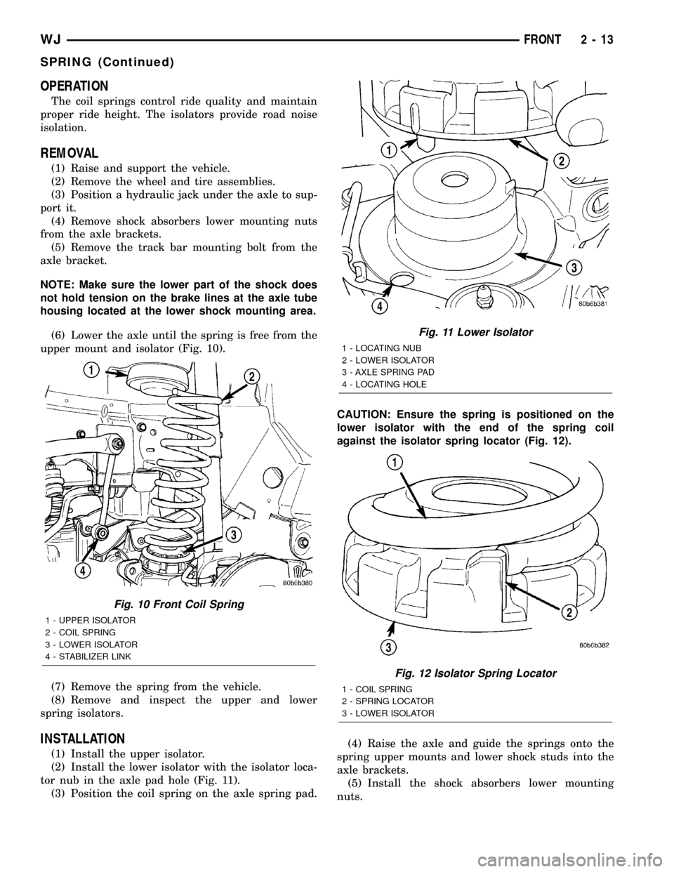
upper mount and isolator (Fig. 10).
(7) Remove the spring from the vehicle.
(8) Remove and inspect the upper and lower
spring isolators.
INSTALLATION
(1) Install the upper isolator.
(2) Install the lower isolator with the isolator loca-
tor nub in the axle pad hole (Fig. 11).
(3) Position the coil spring on the axle spring pad.CAUTION: Ensure the spring is positioned on the
lower isolator with the end of the spring coil
against the isolator spring locator (Fig. 12).
(4) Raise the axle and guide the springs onto the
spring upper mounts and lower shock studs into the
axle brackets.
(5) Install the shock absorbers lower mounting
nuts.
Fig. 10 Front Coil Spring
1 - UPPER ISOLATOR
2 - COIL SPRING
3 - LOWER ISOLATOR
4 - STABILIZER LINK
Fig. 11 Lower Isolator
1 - LOCATING NUB
2 - LOWER ISOLATOR
3 - AXLE SPRING PAD
4 - LOCATING HOLE
Fig. 12 Isolator Spring Locator
1 - COIL SPRING
2 - SPRING LOCATOR
3 - LOWER ISOLATOR
WJFRONT 2 - 13
SPRING (Continued)
Page 35 of 2199
(6) Install the track bar to the axle bracket and
install the mounting bolt.
NOTE: It may be necessary to pry the axle assem-
bly over to install the track bar bolt.
(7) Remove the hydraulic jack from under the
vehicle.
(8) Tighten all suspension components to proper
torque.
(9) Install the wheel and tire assemblies.
(10) Remove support and lower vehicle.
STABILIZER BAR
DESCRIPTION
The bar extends across the front underside of the
chassis and is mounted to the frame rails. Links are
connected from the bar to the axle brackets. The sta-
bilizer bar and links are isolated by rubber bushings.
OPERATION
The stabilizer bar is used to control vehicle body
roll during turns. The spring steel bar helps to con-
trol the vehicle body in relationship to the suspen-
sion.
REMOVAL
(1) Raise and support the vehicle.
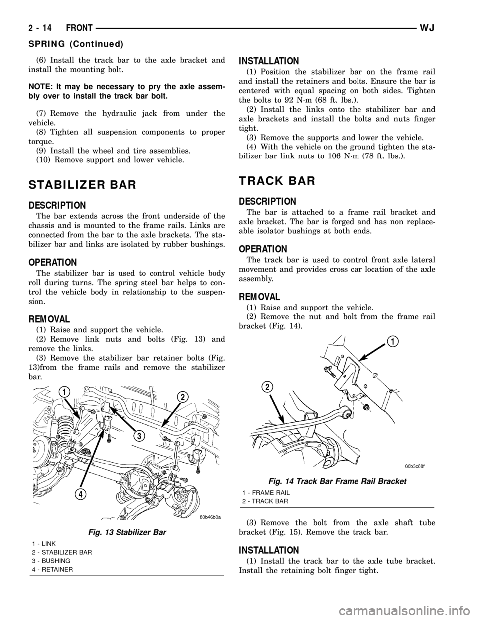
(2) Remove link nuts and bolts (Fig. 13) and
remove the links.
(3) Remove the stabilizer bar retainer bolts (Fig.
13)from the frame rails and remove the stabilizer
bar.
INSTALLATION
(1) Position the stabilizer bar on the frame rail
and install the retainers and bolts. Ensure the bar is
centered with equal spacing on both sides. Tighten
the bolts to 92 N´m (68 ft. lbs.).
(2) Install the links onto the stabilizer bar and
axle brackets and install the bolts and nuts finger
tight.
(3) Remove the supports and lower the vehicle.
(4) With the vehicle on the ground tighten the sta-
bilizer bar link nuts to 106 N´m (78 ft. lbs.).
TRACK BAR
DESCRIPTION
The bar is attached to a frame rail bracket and
axle bracket. The bar is forged and has non replace-
able isolator bushings at both ends.
OPERATION
The track bar is used to control front axle lateral
movement and provides cross car location of the axle
assembly.
REMOVAL
(1) Raise and support the vehicle.
(2) Remove the nut and bolt from the frame rail
bracket (Fig. 14).
(3) Remove the bolt from the axle shaft tube
bracket (Fig. 15). Remove the track bar.
INSTALLATION
(1) Install the track bar to the axle tube bracket.
Install the retaining bolt finger tight.
Fig. 13 Stabilizer Bar
1 - LINK
2 - STABILIZER BAR
3 - BUSHING
4 - RETAINER
Fig. 14 Track Bar Frame Rail Bracket
1 - FRAME RAIL
2 - TRACK BAR
2 - 14 FRONTWJ
SPRING (Continued)
Page 39 of 2199
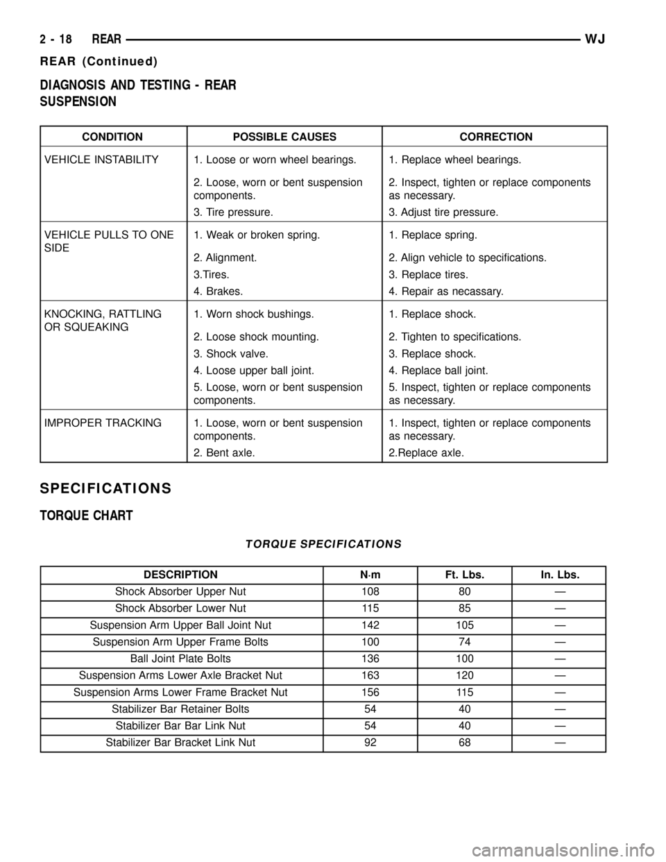
DIAGNOSIS AND TESTING - REAR
SUSPENSION
CONDITION POSSIBLE CAUSES CORRECTION
VEHICLE INSTABILITY 1. Loose or worn wheel bearings. 1. Replace wheel bearings.
2. Loose, worn or bent suspension
components.2. Inspect, tighten or replace components
as necessary.
3. Tire pressure. 3. Adjust tire pressure.
VEHICLE PULLS TO ONE
SIDE1. Weak or broken spring. 1. Replace spring.
2. Alignment. 2. Align vehicle to specifications.
3.Tires. 3. Replace tires.
4. Brakes. 4. Repair as necassary.
KNOCKING, RATTLING
OR SQUEAKING1. Worn shock bushings. 1. Replace shock.
2. Loose shock mounting. 2. Tighten to specifications.
3. Shock valve. 3. Replace shock.
4. Loose upper ball joint. 4. Replace ball joint.
5. Loose, worn or bent suspension
components.5. Inspect, tighten or replace components
as necessary.
IMPROPER TRACKING 1. Loose, worn or bent suspension
components.1. Inspect, tighten or replace components
as necessary.
2. Bent axle. 2.Replace axle.
SPECIFICATIONS
TORQUE CHART
TORQUE SPECIFICATIONS
DESCRIPTION N´m Ft. Lbs. In. Lbs.
Shock Absorber Upper Nut 108 80 Ð
Shock Absorber Lower Nut 115 85 Ð
Suspension Arm Upper Ball Joint Nut 142 105 Ð
Suspension Arm Upper Frame Bolts 100 74 Ð
Ball Joint Plate Bolts 136 100 Ð
Suspension Arms Lower Axle Bracket Nut 163 120 Ð
Suspension Arms Lower Frame Bracket Nut 156 115 Ð
Stabilizer Bar Retainer Bolts 54 40 Ð
Stabilizer Bar Bar Link Nut 54 40 Ð
Stabilizer Bar Bracket Link Nut 92 68 Ð
2 - 18 REARWJ
REAR (Continued)
Page 41 of 2199
SPRING
DESCRIPTION
The coil springs mount up in the wheelhouse which
is part of the unitized body bracket. A rubber dough-
nut isolator is located between the top of the spring
and the body. The bottom of the spring seats on a
axle isolator made of rubber with a steel insert. The
isolators provide road noise isolation
OPERATION
The coil springs control ride quality and maintain
proper ride height.
REMOVAL
(1) Raise and support the vehicle. Position a
hydraulic jack under the axle to support the axle.
(2) Remove the wheel and tire assemblies.
(3) Remove the stabilizer bar link from the stabi-
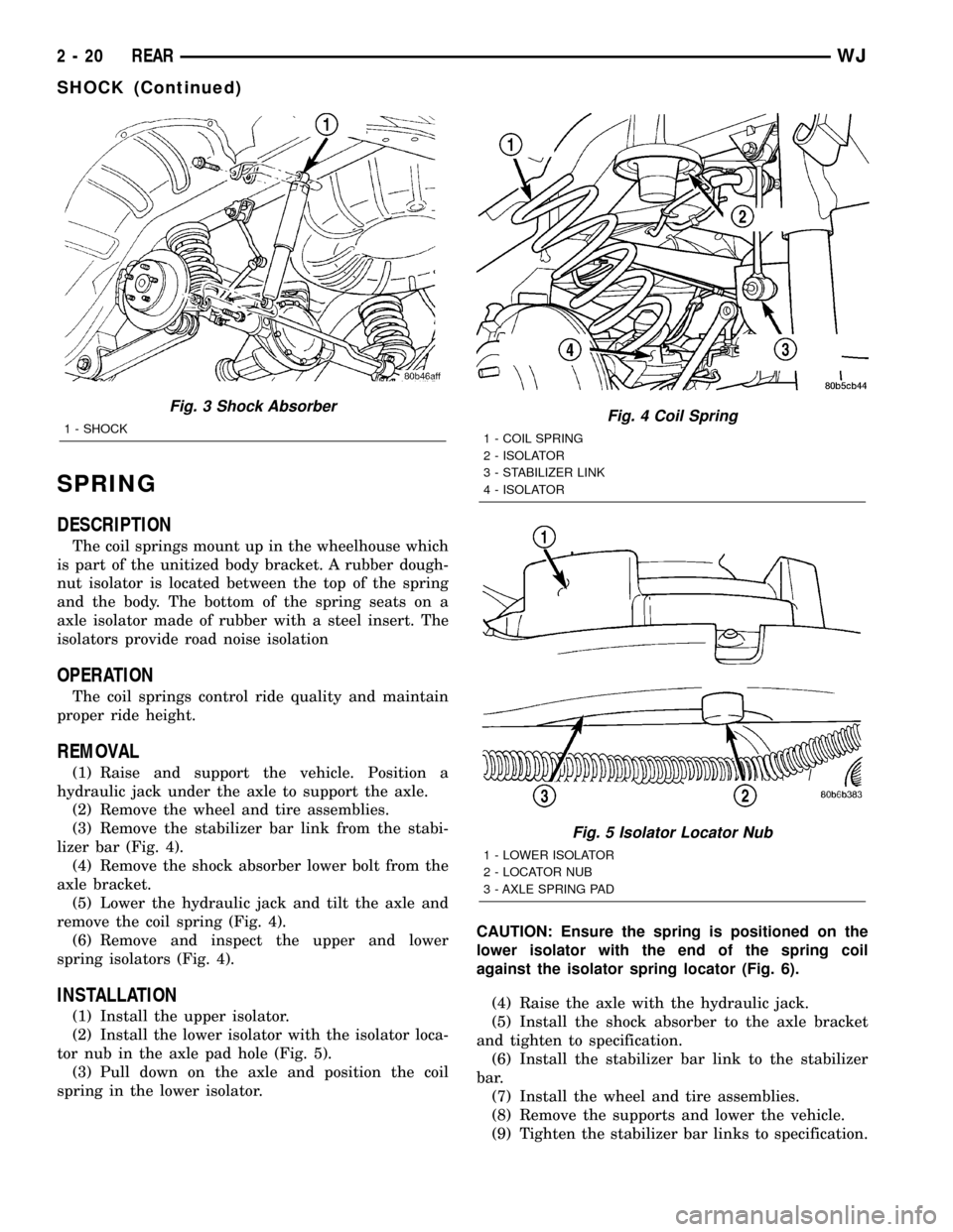
lizer bar (Fig. 4).
(4) Remove the shock absorber lower bolt from the
axle bracket.
(5) Lower the hydraulic jack and tilt the axle and
remove the coil spring (Fig. 4).
(6) Remove and inspect the upper and lower
spring isolators (Fig. 4).
INSTALLATION
(1) Install the upper isolator.
(2) Install the lower isolator with the isolator loca-
tor nub in the axle pad hole (Fig. 5).
(3) Pull down on the axle and position the coil
spring in the lower isolator.CAUTION: Ensure the spring is positioned on the
lower isolator with the end of the spring coil
against the isolator spring locator (Fig. 6).
(4) Raise the axle with the hydraulic jack.
(5) Install the shock absorber to the axle bracket
and tighten to specification.
(6) Install the stabilizer bar link to the stabilizer
bar.
(7) Install the wheel and tire assemblies.
(8) Remove the supports and lower the vehicle.
(9) Tighten the stabilizer bar links to specification.
Fig. 3 Shock Absorber
1 - SHOCKFig. 4 Coil Spring
1 - COIL SPRING
2 - ISOLATOR
3 - STABILIZER LINK
4 - ISOLATOR
Fig. 5 Isolator Locator Nub
1 - LOWER ISOLATOR
2 - LOCATOR NUB
3 - AXLE SPRING PAD
2 - 20 REARWJ
SHOCK (Continued)
Page 46 of 2199
DIFFERENTIAL & DRIVELINE
TABLE OF CONTENTS
page page
PROPELLER SHAFT......................1
FRONT TUBE AXLE......................14
FRONT AXLE - 186FBI....................15REAR AXLE - 198RBI.....................50
REAR AXLE - 226RBA....................90
PROPELLER SHAFT
TABLE OF CONTENTS
page page
PROPELLER SHAFT
DIAGNOSIS AND TESTING................1
STANDARD PROCEDURES................3
SPECIFICATIONS........................5
SPECIAL TOOLS........................5
PROPELLER SHAFT - FRONT
REMOVAL.............................6
INSTALLATION..........................6
PROPELLER SHAFT - FRONT 4.7L
REMOVAL.............................6INSTALLATION..........................7
PROPELLER SHAFT - REAR
REMOVAL.............................7
INSTALLATION..........................7
SINGLE CARDAN UNIVERSAL JOINTS
DISASSEMBLY..........................8
ASSEMBLY.............................9
DOUBLE CARDAN UNIVERSAL JOINTS
DISASSEMBLY..........................9
ASSEMBLY............................10
PROPELLER SHAFT
DIAGNOSIS AND TESTING
VIBRATION
Tires that are out-of-round, or wheels that are
unbalanced, will cause a low frequency vibration.
(Refer to 22 - TIRES/WHEELS - DIAGNOSIS AND
TESTING)
Brake rotors that are unbalanced will cause a
harsh, low frequency vibration. (Refer to 5 - BRAKES
- DIAGNOSIS AND TESTING)Driveline vibration can also result from loose or
damaged engine mounts.
Propeller shaft vibration increases as the vehicle
speed is increased. A vibration that occurs within a
specific speed range is not usually caused by a pro-
peller shaft being unbalanced. Defective universal
joints, or an incorrect propeller shaft angle, are usu-
ally the cause of such a vibration.
WJDIFFERENTIAL & DRIVELINE 3 - 1
Page 47 of 2199
DRIVELINE VIBRATION
Drive Condition Possible Cause Correction
Propeller Shaft Noise 1) Undercoating or other foreign material
on shaft.1) Clean exterior of shaft and wash with
solvent.
2) Loose U-joint clamp screws. 2) Install new clamps and screws and
tighten to proper torque.
3) Loose or bent U-joint yoke or
excessive runout.3) Install new yoke.
4) Incorrect driveline angularity. 4) Measure and correct driveline angles.
5) Rear spring center bolt not in seat. 5) Loosen spring u-bolts and seat center
bolt.
6) Worn U-joint bearings. 6) Install new U-joint.
7) Propeller shaft damaged or out of
balance.7) Installl new propeller shaft.
8) Broken rear spring. 8) Install new rear spring.
9) Excessive runout or unbalanced
condition.9) Re-index propeller shaft, test, and
evaluate.
10) Excessive drive pinion gear shaft
runout.10) Re-index propeller shaft and evaluate.
11) Excessive axle yoke deflection. 11) Inspect and replace yoke if necessary.
12) Excessive transfer case runout. 12) Inspect and repair as necessary.
Universal Joint Noise 1) Loose U-joint clamp screws. 1) Install new clamps and screws and
tighten to proper torque.
2) Lack of lubrication. 2) Replace U-joints as necessary.
BALANCE
NOTE: Removing and re-indexing the propeller
shaft 180É relative to the yoke may eliminate some
vibrations.
If propeller shaft is suspected of being unbalanced,
it can be verified with the following procedure:
(1) Raise the vehicle.
(2) Clean all the foreign material from the propel-
ler shaft and the universal joints.
(3) Inspect the propeller shaft for missing balance
weights, broken welds, and bent areas.If the pro-
peller shaft is bent, it must be replaced.
(4) Inspect the universal joints to ensure that they
are not worn, are properly installed, and are cor-
rectly aligned with the shaft.
(5) Check the universal joint clamp screws torque.
(6) Remove the wheels and tires. Install the wheel
lug nuts to retain the brake drums or rotors.
(7) Mark and number the shaft six inches from the
yoke end at four positions 90É apart.
(8) Run and accelerate the vehicle until vibration
occurs. Note the intensity and speed the vibration
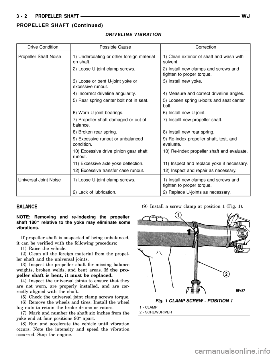
occurred. Stop the engine.(9) Install a screw clamp at position 1 (Fig. 1).
Fig. 1 CLAMP SCREW - POSITION 1
1 - CLAMP
2 - SCREWDRIVER
3 - 2 PROPELLER SHAFTWJ
PROPELLER SHAFT (Continued)