Brake JEEP GRAND CHEROKEE 2003 WJ / 2.G Workshop Manual
[x] Cancel search | Manufacturer: JEEP, Model Year: 2003, Model line: GRAND CHEROKEE, Model: JEEP GRAND CHEROKEE 2003 WJ / 2.GPages: 2199, PDF Size: 76.01 MB
Page 1876 of 2199

(2) Apply silicone lubricant to a cloth and wipe it
on door seals to avoid over-spray that can soil pas-
senger's clothing.
(3) Before applying lubricant, the component
should be wiped clean. After lubrication, any excess
lubricant should be removed.
(4) The hood latch, latch release mechanism, latch
striker, and safety latch should be lubricated period-
ically.
(5) The door lock cylinders should be lubricated
twice each year (preferably autumn and spring).
(a) Spray a small amount of lock cylinder lubri-
cant directly into the lock cylinder.
(b) Apply a small amount to the key and insert
it into the lock cylinder.
(c) Rotate it to the locked position and then back
to the unlocked position several times.(d) Remove the key. Wipe the lubricant from it
with a clean cloth to avoid soiling of clothing.
STANDARD PROCEDURE - DRILLING AND
WELDING
When holes must be drilled or punched in an inner
body panel, verify depth of space to the outer body
panel, electrical wiring, or other components. Dam-
age to vehicle can result.
Do not weld exterior panels unless combustible
material on the interior of vehicle is removed from
the repair area. Fire or hazardous conditions, can
result.
Always have a fire extinguisher ready for use when
welding.
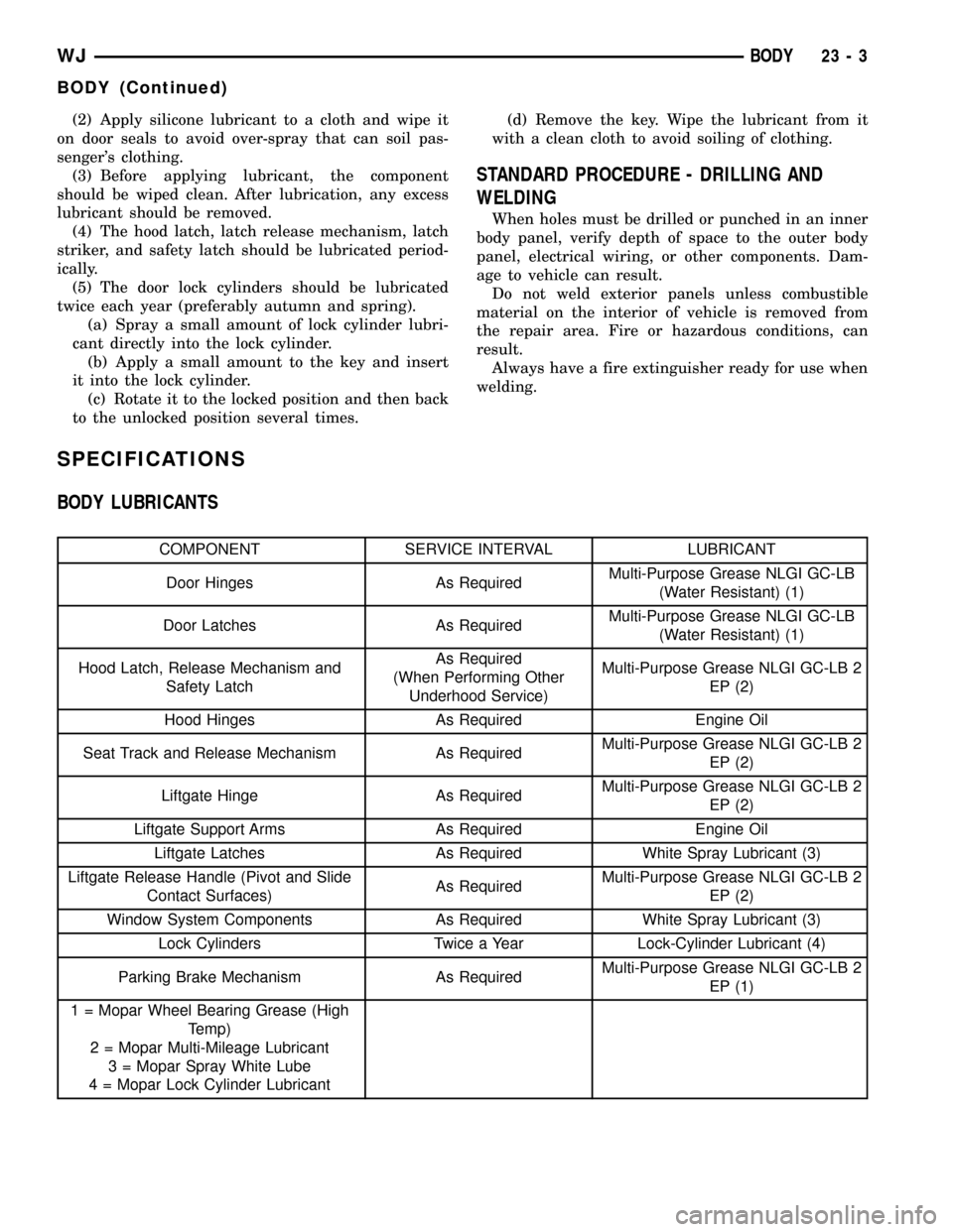
SPECIFICATIONS
BODY LUBRICANTS
COMPONENT SERVICE INTERVAL LUBRICANT
Door Hinges As RequiredMulti-Purpose Grease NLGI GC-LB
(Water Resistant) (1)
Door Latches As RequiredMulti-Purpose Grease NLGI GC-LB
(Water Resistant) (1)
Hood Latch, Release Mechanism and
Safety LatchAs Required
(When Performing Other
Underhood Service)Multi-Purpose Grease NLGI GC-LB 2
EP (2)
Hood Hinges As Required Engine Oil
Seat Track and Release Mechanism As RequiredMulti-Purpose Grease NLGI GC-LB 2
EP (2)
Liftgate Hinge As RequiredMulti-Purpose Grease NLGI GC-LB 2
EP (2)
Liftgate Support Arms As Required Engine Oil
Liftgate Latches As Required White Spray Lubricant (3)
Liftgate Release Handle (Pivot and Slide
Contact Surfaces)As RequiredMulti-Purpose Grease NLGI GC-LB 2
EP (2)
Window System Components As Required White Spray Lubricant (3)
Lock Cylinders Twice a Year Lock-Cylinder Lubricant (4)
Parking Brake Mechanism As RequiredMulti-Purpose Grease NLGI GC-LB 2
EP (1)
1 = Mopar Wheel Bearing Grease (High
Temp)
2 = Mopar Multi-Mileage Lubricant
3 = Mopar Spray White Lube
4 = Mopar Lock Cylinder Lubricant
WJBODY 23 - 3
BODY (Continued)
Page 1912 of 2199

(18) Remove the four nuts that secure the steering
column to the studs on the instrument panel steering
column support bracket.
(19) Remove the steering column from the instru-
ment panel. Be certain that the steering wheel is
locked and secured from rotation to prevent the loss
of clockspring centering.
(20) Disconnect the left and right body wire har-
ness connectors, the Ignition Off Draw (IOD) wire
harness connector and the fused B(+) wire harness
connector from the connector receptacles of the JB
(Fig. 5).(21) Disconnect the instrument panel wire harness
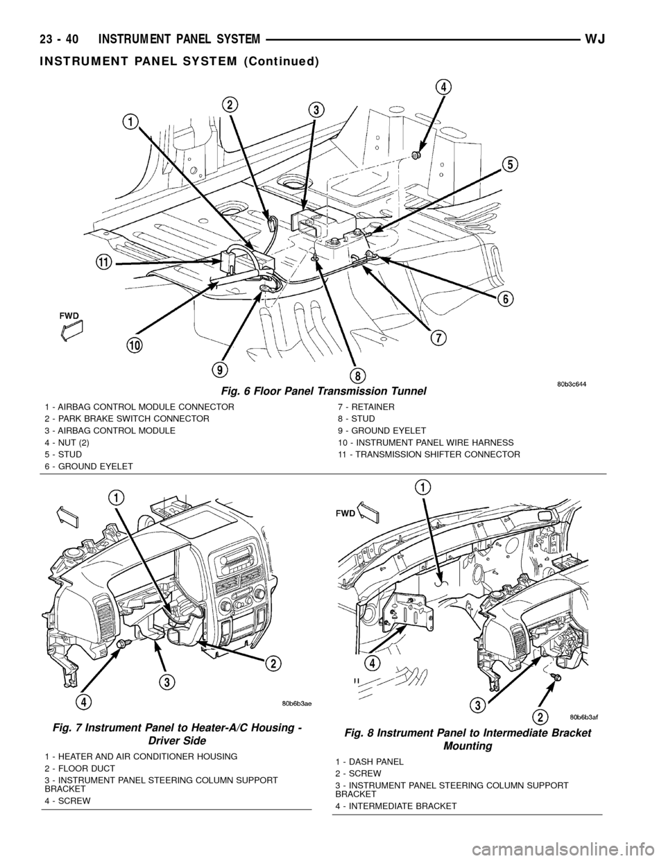
connectors from the following floor panel transmis-
sion tunnel components (Fig. 6):
²the Airbag Control Module (ACM) connector
receptacle
²the park brake switch terminal
²the transmission shifter connector receptacle.
(22) Remove the two nuts that secure the instru-
ment panel wire harness ground eyelets to the studs
on the floor panel transmission tunnel in front of and
behind the ACM.
(23) Disengage the retainers that secure the
instrument panel wire harness to the floor panel
transmission tunnel.
(24) Remove the instrument panel to center floor
tunnel bracket from the instrument panel and the
floor panel transmission tunnel. (Refer to 23 - BODY/
INSTRUMENT PANEL/IP CENTER FLOOR TUN-
NEL BRACKET - REMOVAL).
(25) Remove the one screw that secures the floor
duct to the heater and air conditioner housing near
the driver side of the floor panel transmission tunnel
and remove the duct from the housing.
(26) If the vehicle is equipped with the manual
heating and air conditioning system, disconnect the
vacuum harness connector located near the driver
side of the floor panel transmission tunnel behind
the driver side floor duct.
(27) Remove the one screw that secures the instru-
ment panel steering column support bracket to the
driver side end of the heater and air conditioner
housing (Fig. 7).
(28) Remove the one screw that secures the instru-
ment panel steering column support bracket to the
intermediate bracket on the driver side dash panel
(Fig. 8).
Fig. 5 Junction Block Connections
1 - SNAP CLIPS
2 - SCREW
3 - CONNECTOR
4 - LEFT BODY WIRE HARNESS
5 - IOD CONNECTOR
6 - FUSED B+ CONNECTOR
7 - RIGHT BODY WIRE HARNESS
8 - SCREW
9 - CONNECTOR
10 - JUNCTION BLOCK
WJINSTRUMENT PANEL SYSTEM 23 - 39
INSTRUMENT PANEL SYSTEM (Continued)
Page 1913 of 2199

Fig. 6 Floor Panel Transmission Tunnel
1 - AIRBAG CONTROL MODULE CONNECTOR
2 - PARK BRAKE SWITCH CONNECTOR
3 - AIRBAG CONTROL MODULE
4 - NUT (2)
5 - STUD
6 - GROUND EYELET7 - RETAINER
8 - STUD
9 - GROUND EYELET
10 - INSTRUMENT PANEL WIRE HARNESS
11 - TRANSMISSION SHIFTER CONNECTOR
Fig. 7 Instrument Panel to Heater-A/C Housing -
Driver Side
1 - HEATER AND AIR CONDITIONER HOUSING
2 - FLOOR DUCT
3 - INSTRUMENT PANEL STEERING COLUMN SUPPORT
BRACKET
4 - SCREW
Fig. 8 Instrument Panel to Intermediate Bracket
Mounting
1 - DASH PANEL
2 - SCREW
3 - INSTRUMENT PANEL STEERING COLUMN SUPPORT
BRACKET
4 - INTERMEDIATE BRACKET
23 - 40 INSTRUMENT PANEL SYSTEMWJ
INSTRUMENT PANEL SYSTEM (Continued)
Page 1917 of 2199

(23) Reconnect the instrument panel wire harness
connectors to the following floor panel transmission
tunnel components:
²the Airbag Control Module (ACM) connector
receptacle
²the park brake switch terminal
²the transmission shifter connector receptacle.
(24) Reconnect the left and right body wire har-
ness connectors, the Ignition Off Draw (IOD) wire
harness connector and the fused B(+) wire harness
connector to the connector receptacles of the Junction
Block (JB) and tighten the connector screws (Fig. 5).
Tighten the screws to 4 N´m (36 in. lbs.).
(25) Engage the lower steering column shaft with
the steering shaft coupler and position the steering
column to the mounting studs on the instrument
panel steering column support bracket (Fig. 4).
(26) Install and tighten the four nuts that secure
the steering column to the studs on the instrument
panel steering column support bracket. Tighten the
nuts to 11.8 N´m (105 in. lbs.).
(27) Install and tighten the bolt that secures the
coupler to the lower steering column shaft. Tighten
the bolt to 49 N´m (36 ft. lbs.).
(28) Turn the ignition switch to the On position,
then install the shifter interlock cable connector into
the ignition lock housing receptacle.
(29) Reconnect the instrument panel wire harness
connectors to the following steering column compo-
nents (Fig. 3):
²the two lower clockspring connector receptacles
²the left multi-function switch connector recepta-
cle
²the right multi-function switch connector recep-
tacle
²the two ignition switch connector receptacles
²the shifter interlock solenoid connector recepta-
cle
²if the vehicle is so equipped, the Sentry Key
Immobilizer Module (SKIM) connector receptacle.
(30) Position the lower tilting steering column
shroud to the steering column multi-function switchmounting housing, then install and tighten the screw
that secures the shroud to the housing (Fig. 2).
Tighten the screw to 1.9 N´m (17 in. lbs.).
(31) Position the upper tilting steering column
shroud over the steering column. Align the upper and
lower shrouds with each other and snap the two
halves together.
(32) Reinstall the steering column bracket onto the
instrument panel steering column support bracket.
(Refer to 23 - BODY/INSTRUMENT PANEL/IP
STEERING COLUMN BRACKET - INSTALLA-
TION).
(33) Reinstall the steering column opening cover
onto the instrument panel. (Refer to 23 - BODY/IN-
STRUMENT PANEL/STEERING COLUMN OPEN-
ING COVER - INSTALLATION).
(34) Reinstall the cluster bezel onto the instru-
ment panel. (Refer to 23 - BODY/INSTRUMENT
PANEL/CLUSTER BEZEL - INSTALLATION).
(35) Reinstall the fuse cover onto the Junction
Block (JB). (Refer to 8 - ELECTRICAL/POWER DIS-
TRIBUTION/FUSE COVER - INSTALLATION).
(36) Reinstall the console onto the floor panel
transmission tunnel. (Refer to 23 - BODY/INTERI-
OR/FLOOR CONSOLE - INSTALLATION).
(37) Reinstall the trim panels onto the right and
left inner cowl sides. (Refer to 23 - BODY/INTERI-
OR/COWL TRIM - INSTALLATION).
(38) Reinstall the scuff plates onto the right and
left front door sills. (Refer to 23 - BODY/INTERIOR/
DOOR SILL SCUFF PLATE - INSTALLATION).
(39) Reinstall the top cover onto the instrument
panel. (Refer to 23 - BODY/INSTRUMENT PANEL/
INSTRUMENT PANEL TOP COVER - INSTALLA-
TION).
(40) Reinstall the trim onto the right and left
A-pillars. (Refer to 23 - BODY/INTERIOR/A-PILLAR
TRIM - INSTALLATION).
(41) Reconnect the battery negative cable.
23 - 44 INSTRUMENT PANEL SYSTEMWJ
INSTRUMENT PANEL SYSTEM (Continued)
Page 1949 of 2199

FLOOR CONSOLE
REMOVAL
CAUTION: The ACM should be depowered by dis-
connecting the negative battery cable in any opera-
tion requiring the key to be turned ªONº, while
working in the console area. E.G. console, carpet,
or seat removal or installation; shifter linkage
adjustment or replacement; parking brake cable
replacement or adjustment. Failure to take proper
precautions could result in accidental airbag
deployment and possible personal injury.
(1) Set park brake.
(2) Place transmission shift lever and transfer case
lever in full rearward position.
(3) Remove mat from front bin and remove screws
attaching front of console to floor (Fig. 8).
(4) Remove screws attaching rear bin to console.
(5) Remove rear bin.
(6) Pull rear passenger cupholder outward to
access screws.
(7)
Remove screws attaching rear of console to floor.
(8) Lift the console upward and rearward.
(9) Remove console from vehicle.
INSTALLATION
CAUTION: The ACM should be depowered by dis-
connecting the negative battery cable in any opera-
tion requiring the key to be turned ªONº, while
working in the console area. E.G. console, carpet,
or seat removal or installation; shifter linkage
adjustment or replacement; parking brake cable
replacement or adjustment. Failure to take proper
precautions could result in accidental airbag
deployment and possible personal injury.
(1) Position console in vehicle. Ensure rear passen-
ger HEVAC duct is engaged.
(2) Install screws attaching rear of console to floor.
(3) Position rear bin in console.
(4) Install screws attaching rear bin to console.
(5) Install screws attaching front of console to floor
and place front bin mat in front bin.
(6) Return transmission shift lever and transfer
case lever to original position.
(7) Release park brake.
Fig. 8 Floor Console
1 - REAR BIN
2 - CONSOLE LID
3 - SHIFTER CONSOLE
4 - BRACKET5 - PARKING BRAKE
6 - FRONT PIN
7-MAT
23 - 76 INTERIORWJ
Page 2164 of 2199

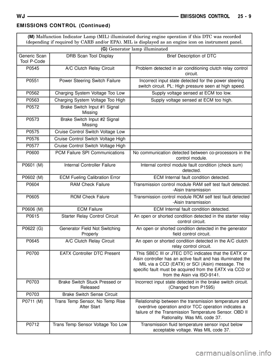
(M)Malfunction Indicator Lamp (MIL) illuminated during engine operation if this DTC was recorded
(depending if required by CARB and/or EPA). MIL is displayed as an engine icon on instrument panel.
(G)Generator lamp illuminated
Generic Scan
Tool P-CodeDRB Scan Tool Display Brief Description of DTC
P0545 A/C Clutch Relay Circuit Problem detected in air conditioning clutch relay control
circuit.
P0551 Power Steering Switch Failure Incorrect input state detected for the power steering
switch circuit. PL: High pressure seen at high speed.
P0562 Charging System Voltage Too Low Supply voltage sensed at ECM too low.
P0563 Charging System Voltage Too High Supply voltage sensed at ECM too high.
P0572 Brake Switch Input #1 Signal
Missing
P0573 Brake Switch Input #2 Signal
Missing
P0575 Cruise Control Switch Voltage Low
P0576 Cruise Control Switch Voltage High
P0577 Cruise Control Switch Voltage High
P0600 PCM Failure SPI Communications No communication detected between co-processors in the
control module.
P0601 (M) Internal Controller Failure Internal control module fault condition (check sum)
detected.
P0602 (M) ECM Fueling Calibration Error ECM Internal fault condition detected.
P0604 RAM Check Failure Transmission control module RAM self test fault detected.
-Aisin transmission
P0605 ROM Check Falure Transmission control module ROM self test fault detected
-Aisin transmission
P0606 (M) ECM Failure ECM Internal fault condition detected.
P0615 Starter Relay Control Circuit An open or shorted condition detected in the starter relay
control circuit.
P0622 (G) Generator Field Not Switching
ProperlyAn open or shorted condition detected in the generator
field control circuit.
P0645 A/C Clutch Relay Circuit An open or shorted condition detected in the A/C clutch
relay control circuit.
P0700 EATX Controller DTC Present This SBEC III or JTEC DTC indicates that the EATX or
Aisin controller has an active fault and has illuminated the
MIL via a CCD (EATX) or SCI (Aisin) message. The
specific fault must be acquired from the EATX via CCD or
from the Aisin via ISO-9141.
P0703 Brake Switch Stuck Pressed or
ReleasedIncorrect input state detected in the brake switch circuit.
(Changed from P1595)
P0703 Brake Switch Sense Circuit
P0711 (M) Trans Temp Sensor, No Temp Rise
After StartRelationship between the transmission temperature and
overdrive operation and/or TCC operation indicates a
failure of the Transmission Temperature Sensor. OBD II
Rationality. Was MIL code 37.
P0712 Trans Temp Sensor Voltage Too Low Transmission fluid temperature sensor input below
acceptable voltage. Was MIL code 37.
WJEMISSIONS CONTROL 25 - 9
EMISSIONS CONTROL (Continued)
Page 2184 of 2199

INSTALLATION - FIXED ORIFICE FITTING
When installing fixed orifice fitting, be sure loca-
tions of fixed orifice fitting and air inlet fitting (Fig.
9) have not been inadvertently exchanged. The fixed
orifice fitting is light grey in color and is located at
rearof valve cover. The air inlet fitting is black in
color and is located atfrontof valve cover.
(1) Connect fitting to CCV breather tube.
(2) Return fixed orifice fitting to valve cover grom-
met.
EVAP/PURGE SOLENOID
DESCRIPTION
The duty cycle EVAP canister purge solenoid (DCP)
regulates the rate of vapor flow from the EVAP can-
ister to the intake manifold. The Powertrain Control
Module (PCM) operates the solenoid.
OPERATION
During the cold start warm-up period and the hot
start time delay, the PCM does not energize the sole-
noid. When de-energized, no vapors are purged. The
PCM de-energizes the solenoid during open loop oper-
ation.
The engine enters closed loop operation after it
reaches a specified temperature and the time delay
ends. During closed loop operation, the PCM cycles
(energizes and de-energizes) the solenoid 5 or 10
times per second, depending upon operating condi-
tions. The PCM varies the vapor flow rate by chang-
ing solenoid pulse width. Pulse width is the amount
of time that the solenoid is energized. The PCM
adjusts solenoid pulse width based on engine operat-
ing condition.
REMOVAL
The duty cycle evaporative (EVAP) canister purge
solenoid is located in the engine compartment near
the brake master cylinder (Fig. 10).
(1) Disconnect electrical connector at solenoid.
(2) Disconnect vacuum lines at solenoid.
(3) Lift solenoid slot (Fig. 10) from mounting
bracket for removal.
INSTALLATION
(1) Position solenoid slot to mounting bracket.
(2) Connect vacuum lines to solenoid. Be sure vac-
uum lines are firmly connected and not leaking or
damaged. If leaking, a Diagnostic Trouble Code
(DTC) may be set with certain emission packages.
(3) Connect electrical connector to solenoid.
FUEL FILLER CAP
DESCRIPTION
The plastic fuel tank filler tube cap is threaded
onto the end of the fuel fill tube. Certain models are
equipped with a 1/4 turn cap.
OPERATION
The loss of any fuel or vapor out of fuel filler tube
is prevented by the use of a pressure-vacuum fuel fill
cap. Relief valves inside the cap will release fuel tank
pressure at predetermined pressures. Fuel tank vac-
uum will also be released at predetermined values.
This cap must be replaced by a similar unit if
replacement is necessary. This is in order for the sys-
tem to remain effective.
CAUTION: Remove fill cap before servicing any fuel
system component to relieve tank pressure. If
equipped with a California emissions package and a
Leak Detection Pump (LDP), the cap must be tight-
ened securely. If cap is left loose, a Diagnostic
Trouble Code (DTC) may be set.
REMOVAL
If replacement of the 1/4 turn fuel tank filler tube
cap is necessary, it must be replaced with an identi-
cal cap to be sure of correct system operation.
Fig. 10 EVAP/PURGE SOLENOID LOCATION
1 - BRAKE MASTER CYLINDER
2 - EVAP SOLENOID
3 - SLOT
4 - ELEC. CONNEC.
5 - VACUUM LINE CONNEC.
6 - TEST PORT
WJEVAPORATIVE EMISSIONS 25 - 29
CCV HOSE (Continued)