Connector pin JEEP GRAND CHEROKEE 2003 WJ / 2.G Workshop Manual
[x] Cancel search | Manufacturer: JEEP, Model Year: 2003, Model line: GRAND CHEROKEE, Model: JEEP GRAND CHEROKEE 2003 WJ / 2.GPages: 2199, PDF Size: 76.01 MB
Page 1171 of 2199
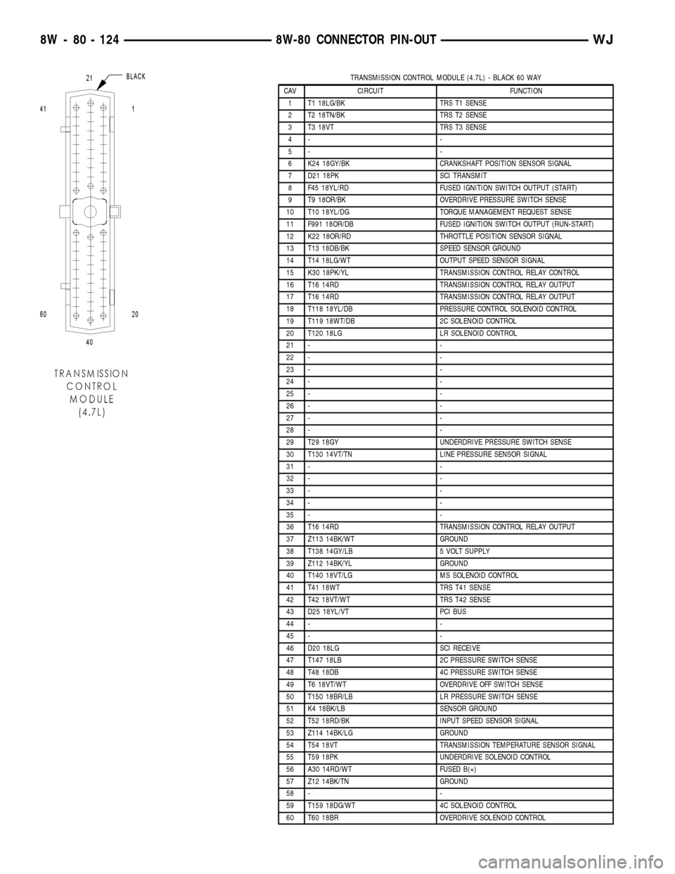
TRANSMISSION CONTROL MODULE (4.7L) - BLACK 60 WAY
CAV CIRCUIT FUNCTION
1 T1 18LG/BK TRS T1 SENSE
2 T2 18TN/BK TRS T2 SENSE
3 T3 18VT TRS T3 SENSE
4- -
5- -
6 K24 18GY/BK CRANKSHAFT POSITION SENSOR SIGNAL
7 D21 18PK SCI TRANSMIT
8 F45 18YL/RD FUSED IGNITION SWITCH OUTPUT (START)
9 T9 18OR/BK OVERDRIVE PRESSURE SWITCH SENSE
10 T10 18YL/DG TORQUE MANAGEMENT REQUEST SENSE
11 F991 18OR/DB FUSED IGNITION SWITCH OUTPUT (RUN-START)
12 K22 18OR/RD THROTTLE POSITION SENSOR SIGNAL
13 T13 18DB/BK SPEED SENSOR GROUND
14 T14 18LG/WT OUTPUT SPEED SENSOR SIGNAL
15 K30 18PK/YL TRANSMISSION CONTROL RELAY CONTROL
16 T16 14RD TRANSMISSION CONTROL RELAY OUTPUT
17 T16 14RD TRANSMISSION CONTROL RELAY OUTPUT
18 T118 18YL/DB PRESSURE CONTROL SOLENOID CONTROL
19 T119 18WT/DB 2C SOLENOID CONTROL
20 T120 18LG LR SOLENOID CONTROL
21 - -
22 - -
23 - -
24 - -
25 - -
26 - -
27 - -
28 - -
29 T29 18GY UNDERDRIVE PRESSURE SWITCH SENSE
30 T130 14VT/TN LINE PRESSURE SENSOR SIGNAL
31 - -
32 - -
33 - -
34 - -
35 - -
36 T16 14RD TRANSMISSION CONTROL RELAY OUTPUT
37 Z113 14BK/WT GROUND
38 T138 14GY/LB 5 VOLT SUPPLY
39 Z112 14BK/YL GROUND
40 T140 18VT/LG MS SOLENOID CONTROL
41 T41 18WT TRS T41 SENSE
42 T42 18VT/WT TRS T42 SENSE
43 D25 18YL/VT PCI BUS
44 - -
45 - -
46 D20 18LG SCI RECEIVE
47 T147 18LB 2C PRESSURE SWITCH SENSE
48 T48 18DB 4C PRESSURE SWITCH SENSE
49 T6 18VT/WT OVERDRIVE OFF SWITCH SENSE
50 T150 18BR/LB LR PRESSURE SWITCH SENSE
51 K4 18BK/LB SENSOR GROUND
52 T52 18RD/BK INPUT SPEED SENSOR SIGNAL
53 Z114 14BK/LG GROUND
54 T54 18VT TRANSMISSION TEMPERATURE SENSOR SIGNAL
55 T59 18PK UNDERDRIVE SOLENOID CONTROL
56 A30 14RD/WT FUSED B(+)
57 Z12 14BK/TN GROUND
58 - -
59 T159 18DG/WT 4C SOLENOID CONTROL
60 T60 18BR OVERDRIVE SOLENOID CONTROL
8W - 80 - 124 8W-80 CONNECTOR PIN-OUTWJ
Page 1172 of 2199
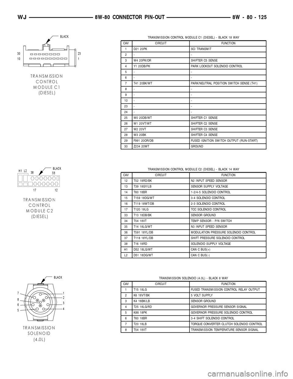
TRANSMISSION CONTROL MODULE C1 (DIESEL) - BLACK 18 WAY
CAV CIRCUIT FUNCTION
1 D21 20PK SCI TRANSMIT
2- -
3 W4 20PK/OR SHIFTER C5 SENSE
4 Y1 20DB/PK PARK LOCKOUT SOLENOID CONTROL
5- -
6- -
7 T41 20BK/WT PARK/NEUTRAL POSITION SWITCH SENSE (T41)
8- -
9- -
10 - -
23 - -
24 - -
25 W0 20DB/WT SHIFTER C1 SENSE
26 W1 20VT/WT SHIFTER C2 SENSE
27 W2 20VT SHIFTER C3 SENSE
28 W3 20BK SHIFTER C4 SENSE
29 F991 20OR/DB FUSED IGNITION SWITCH OUTPUT (RUN-START)
30 Z234 20WT GROUND
TRANSMISSION CONTROL MODULE C2 (DIESEL) - BLACK 14 WAY
CAV CIRCUIT FUNCTION
12 T52 18RD/BK N2 INPUT SPEED SENSOR
13 T39 18GY/LB SENSOR SUPPLY VOLTAGE
14 T60 18BR 1-2/4-5 SOLENOID CONTROL
15 T159 18DG/WT 3-4 SOLENOID CONTROL
16 T119 18WT/DB 2-3 SOLENOID CONTROL
17 T120 18LG TCC SOLENOID CONTROL
33 T13 18DB/BK SENSOR GROUND
34 T54 18VT TEMP SENSOR - P/N SWITCH
35 T14 18LG/WT N3 INPUT SPEED SENSOR
36 T591 18YL/DB MODULATION PRESSURE SOLENOID CONTROL
37 T118 18YL/DB SHIFT PRESSURE SOLENOID CONTROL
38 T16 18RD SOLENOID SUPPLY VOLTAGE
H1 D52 18LG/WT CAN C BUS(+)
L2 D51 18DG/WT CAN C BUS(-)
TRANSMISSION SOLENOID (4.0L) - BLACK 8 WAY
CAV CIRCUIT FUNCTION
1 T15 18LG FUSED TRANSMISSION CONTROL RELAY OUTPUT
2 K6 18VT/BK 5 VOLT SUPPLY
3 K4 18BK/LB SENSOR GROUND
4 T25 18LG/RD GOVERNOR PRESSURE SENSOR SIGNAL
5 K88 18PK GOVERNOR PRESSURE SOLENOID CONTROL
6 T60 18BR 3-4 SHIFT SOLENOID CONTROL
7 T20 18LB TORQUE CONVERTER CLUTCH SOLENOID CONTROL
8 T54 18VT TRANSMISSION TEMPERATURE SENSOR SIGNAL
WJ8W-80 CONNECTOR PIN-OUT 8W - 80 - 125
Page 1173 of 2199
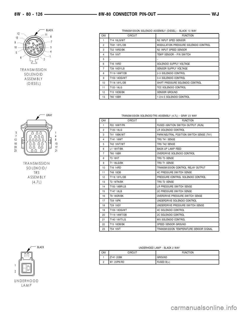
TRANSMISSION SOLENOID ASSEMBLY (DIESEL) - BLACK 13 WAY
CAV CIRCUIT FUNCTION
1 T14 18LG/WT N3 INPUT SPED SENSOR
2 T591 18YL/DB MODULATION PRESSURE SOLENOID CONTROL
3 T52 18RD/BK N2 INPUT SPEED SENSOR
4 T54 18VT TEMP SENSOR - P/N SWITCH
5- -
6 T16 18RD SOLENOID SUPPLY VOLTAGE
7 T39 18GY/LB SENSOR SUPPLY VOLTAGE
8 T119 18WT/DB 2-3 SOLENOID CONTROL
9 T159 18DG/WT 3-4 SOLENOID CONTROL
10 T118 18YL/DB SHIFT PRESSURE SOLENOID CONTROL
11 T120 18LG TCC SOLENOID CONTROL
12 T13 18DB/BK SENSOR GROUND
13 T60 18BR 1-2/4-5 SOLENOID CONTROL
TRANSMISSION SOLENOID/TRS ASSEMBLY (4.7L) - GRAY 23 WAY
CAV CIRCUIT FUNCTION
1 F22 18WT/PK FUSED IGNITION SWITCH OUTPUT (RUN)
2 T120 18LG LR SOLENOID CONTROL
3 T41 18BK/WT PARK/NEUTRAL POSITION SWITCH SENSE (T41)
4 T141 18WT TRS T41 SENSE
5 T42 18VT/WT TRS T42 SENSE
6 L1 18VT/BK BACK-UP LAMP FEED
7 T60 18BR OVERDRIVE SOLENOID CONTROL
8 T3 18VT TRS T3 SENSE
9 T1 18LG/BK TRS T1 SENSE
10 T16 14RD TRANSMISSION CONTROL RELAY OUTPUT
11 T48 18DB 4C PRESSURE SWITCH SENSE
12 T118 18YL/DB PRESSURE CONTROL SOLENOID CONTROL
13 T2 18TN/BK TRS T2 SENSE
14 T150 18BR/LB LR PRESSURE SWITCH SENSE
15 T147 18LB 2C PRESSURE SWITCH SENSE
16 T9 18OR/BK OVERDRIVE PRESSURE SWITCH SENSE
17 T59 18PK UNDERDRIVE SOLENOID CONTROL
18 T29 18GY UNDERDRIVE PRESSURE SWITCH SENSE
19 T159 18DG/WT 4C SOLENOID CONTROL
20 T119 18WT/DB 2C SOLENOID CONTROL
21 T140 18VT/LG MS SOLENOID CONTROL
22 T13 18DB/BK SPEED SENSOR GROUND
23 T54 18VT TRANSMISSION TEMPERATURE SENSOR SIGNAL
UNDERHOOD LAMP - BLACK 2 WAY
CAV CIRCUIT FUNCTION
1 Z141 20BK GROUND
2 M1 20PK/RD FUSED B(+)
8W - 80 - 126 8W-80 CONNECTOR PIN-OUTWJ
Page 1174 of 2199
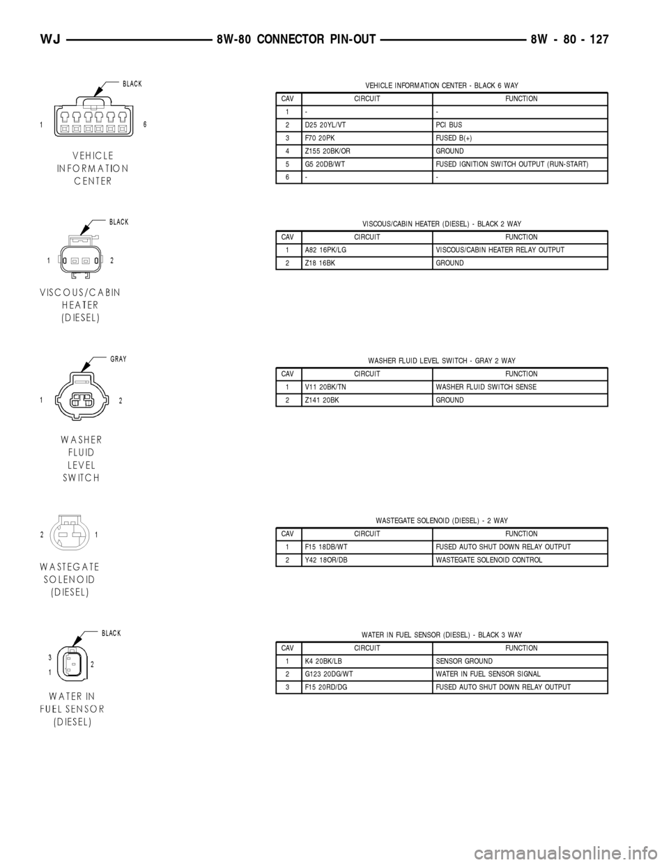
VEHICLE INFORMATION CENTER - BLACK 6 WAY
CAV CIRCUIT FUNCTION
1- -
2 D25 20YL/VT PCI BUS
3 F70 20PK FUSED B(+)
4 Z155 20BK/OR GROUND
5 G5 20DB/WT FUSED IGNITION SWITCH OUTPUT (RUN-START)
6- -
VISCOUS/CABIN HEATER (DIESEL) - BLACK 2 WAY
CAV CIRCUIT FUNCTION
1 A82 16PK/LG VISCOUS/CABIN HEATER RELAY OUTPUT
2 Z18 16BK GROUND
WASHER FLUID LEVEL SWITCH - GRAY 2 WAY
CAV CIRCUIT FUNCTION
1 V11 20BK/TN WASHER FLUID SWITCH SENSE
2 Z141 20BK GROUND
WASTEGATE SOLENOID (DIESEL)-2WAY
CAV CIRCUIT FUNCTION
1 F15 18DB/WT FUSED AUTO SHUT DOWN RELAY OUTPUT
2 Y42 18OR/DB WASTEGATE SOLENOID CONTROL
WATER IN FUEL SENSOR (DIESEL) - BLACK 3 WAY
CAV CIRCUIT FUNCTION
1 K4 20BK/LB SENSOR GROUND
2 G123 20DG/WT WATER IN FUEL SENSOR SIGNAL
3 F15 20RD/DG FUSED AUTO SHUT DOWN RELAY OUTPUT
WJ8W-80 CONNECTOR PIN-OUT 8W - 80 - 127
Page 1232 of 2199
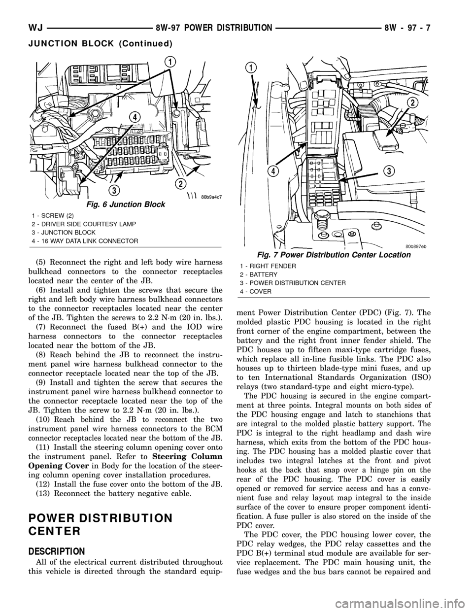
(5) Reconnect the right and left body wire harness
bulkhead connectors to the connector receptacles
located near the center of the JB.
(6) Install and tighten the screws that secure the
right and left body wire harness bulkhead connectors
to the connector receptacles located near the center
of the JB. Tighten the screws to 2.2 N´m (20 in. lbs.).
(7) Reconnect the fused B(+) and the IOD wire
harness connectors to the connector receptacles
located near the bottom of the JB.
(8) Reach behind the JB to reconnect the instru-
ment panel wire harness bulkhead connector to the
connector receptacle located near the top of the JB.
(9) Install and tighten the screw that secures the
instrument panel wire harness bulkhead connector to
the connector receptacle located near the top of the
JB. Tighten the screw to 2.2 N´m (20 in. lbs.).
(10)
Reach behind the JB to reconnect the two
instrument panel wire harness connectors to the BCM
connector receptacles located near the bottom of the JB.
(11) Install the steering column opening cover onto
the instrument panel. Refer toSteering Column
Opening Coverin Body for the location of the steer-
ing column opening cover installation procedures.
(12)
Install the fuse cover onto the bottom of the JB.
(13) Reconnect the battery negative cable.
POWER DISTRIBUTION
CENTER
DESCRIPTION
All of the electrical current distributed throughout
this vehicle is directed through the standard equip-ment Power Distribution Center (PDC) (Fig. 7). The
molded plastic PDC housing is located in the right
front corner of the engine compartment, between the
battery and the right front inner fender shield. The
PDC houses up to fifteen maxi-type cartridge fuses,
which replace all in-line fusible links. The PDC also
houses up to thirteen blade-type mini fuses, and up
to ten International Standards Organization (ISO)
relays (two standard-type and eight micro-type).
The PDC housing is secured in the engine compart-
ment at three points. Integral mounts on both sides of
the PDC housing engage and latch to stanchions that
are integral to the molded plastic battery support. The
PDC is integral to the right headlamp and dash wire
harness, which exits from the bottom of the PDC hous-
ing. The PDC housing has a molded plastic cover that
includes two integral latches at the front and pivot
hooks at the back that snap over a hinge pin on the
rear of the PDC housing. The PDC cover is easily
opened or removed for service access and has a conve-
nient fuse and relay layout map integral to the inside
surface of the cover to ensure proper component identi-
fication. A fuse puller is also stored on the inside of the
PDC cover.
The PDC cover, the PDC housing lower cover, the
PDC relay wedges, the PDC relay cassettes and the
PDC B(+) terminal stud module are available for ser-
vice replacement. The PDC main housing unit, the
fuse wedges and the bus bars cannot be repaired and
Fig. 6 Junction Block
1 - SCREW (2)
2 - DRIVER SIDE COURTESY LAMP
3 - JUNCTION BLOCK
4 - 16 WAY DATA LINK CONNECTOR
Fig. 7 Power Distribution Center Location
1 - RIGHT FENDER
2 - BATTERY
3 - POWER DISTRIBUTION CENTER
4 - COVER
WJ8W-97 POWER DISTRIBUTION 8W - 97 - 7
JUNCTION BLOCK (Continued)
Page 1294 of 2199
crankshaft is drilled internally to pass oil from the
main bearing journals (except number 4 main bear-
ing journal) to the connecting rod journals. Each con-
necting rod bearing cap has a small squirt hole, oil
passes through the squirt hole and is thrown off as
the rod rotates. This oil throwoff lubricates the cam-
shaft lobes, distributor drive gear, cylinder walls, and
piston pins.
The hydraulic valve tappets receive oil directly
from the main oil gallery. Oil is provided to the cam-
shaft bearing through galleries. The front camshaft
bearing journal passes oil through the camshaft
sprocket to the timing chain. Oil drains back to the
oil pan under the number one main bearing cap.
The oil supply for the rocker arms and bridged
pivot assemblies is provided by the hydraulic valve
tappets which pass oil through hollow push rods to a
hole in the corresponding rocker arm. Oil from the
rocker arm lubricates the valve train components,
then passes down through the push rod guide holes
in the cylinder head past the valve tappet area, and
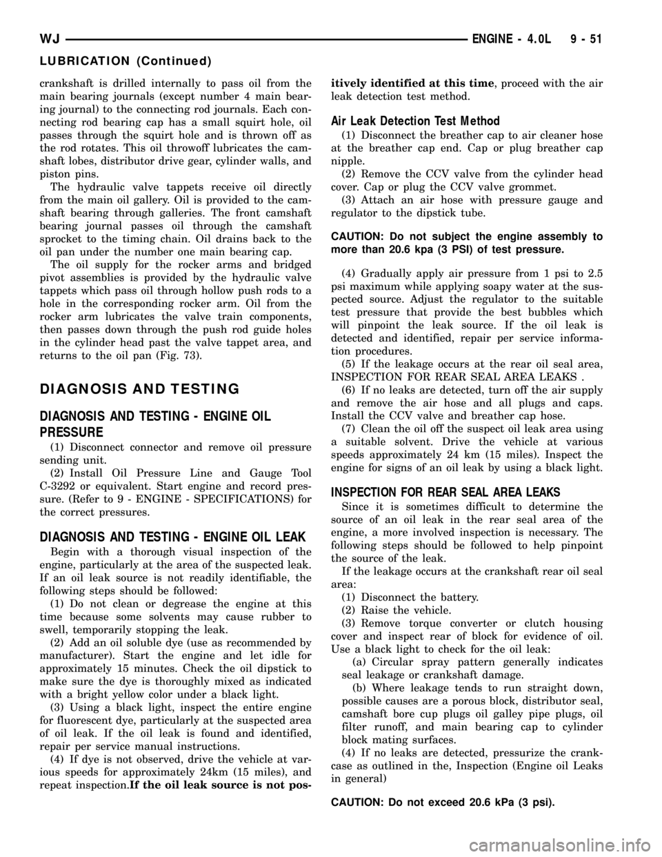
returns to the oil pan (Fig. 73).
DIAGNOSIS AND TESTING
DIAGNOSIS AND TESTING - ENGINE OIL
PRESSURE
(1) Disconnect connector and remove oil pressure
sending unit.
(2) Install Oil Pressure Line and Gauge Tool
C-3292 or equivalent. Start engine and record pres-
sure. (Refer to 9 - ENGINE - SPECIFICATIONS) for
the correct pressures.
DIAGNOSIS AND TESTING - ENGINE OIL LEAK
Begin with a thorough visual inspection of the
engine, particularly at the area of the suspected leak.
If an oil leak source is not readily identifiable, the
following steps should be followed:
(1) Do not clean or degrease the engine at this
time because some solvents may cause rubber to
swell, temporarily stopping the leak.
(2) Add an oil soluble dye (use as recommended by
manufacturer). Start the engine and let idle for
approximately 15 minutes. Check the oil dipstick to
make sure the dye is thoroughly mixed as indicated
with a bright yellow color under a black light.
(3) Using a black light, inspect the entire engine
for fluorescent dye, particularly at the suspected area
of oil leak. If the oil leak is found and identified,
repair per service manual instructions.
(4) If dye is not observed, drive the vehicle at var-
ious speeds for approximately 24km (15 miles), and
repeat inspection.If the oil leak source is not pos-itively identified at this time, proceed with the air
leak detection test method.
Air Leak Detection Test Method
(1) Disconnect the breather cap to air cleaner hose
at the breather cap end. Cap or plug breather cap
nipple.
(2) Remove the CCV valve from the cylinder head
cover. Cap or plug the CCV valve grommet.
(3) Attach an air hose with pressure gauge and
regulator to the dipstick tube.
CAUTION: Do not subject the engine assembly to
more than 20.6 kpa (3 PSI) of test pressure.
(4) Gradually apply air pressure from 1 psi to 2.5
psi maximum while applying soapy water at the sus-
pected source. Adjust the regulator to the suitable
test pressure that provide the best bubbles which
will pinpoint the leak source. If the oil leak is
detected and identified, repair per service informa-
tion procedures.
(5) If the leakage occurs at the rear oil seal area,
INSPECTION FOR REAR SEAL AREA LEAKS .
(6) If no leaks are detected, turn off the air supply
and remove the air hose and all plugs and caps.
Install the CCV valve and breather cap hose.
(7) Clean the oil off the suspect oil leak area using
a suitable solvent. Drive the vehicle at various
speeds approximately 24 km (15 miles). Inspect the
engine for signs of an oil leak by using a black light.
INSPECTION FOR REAR SEAL AREA LEAKS
Since it is sometimes difficult to determine the
source of an oil leak in the rear seal area of the
engine, a more involved inspection is necessary. The
following steps should be followed to help pinpoint
the source of the leak.
If the leakage occurs at the crankshaft rear oil seal
area:
(1) Disconnect the battery.
(2) Raise the vehicle.
(3) Remove torque converter or clutch housing
cover and inspect rear of block for evidence of oil.
Use a black light to check for the oil leak:
(a) Circular spray pattern generally indicates
seal leakage or crankshaft damage.
(b) Where leakage tends to run straight down,
possible causes are a porous block, distributor seal,
camshaft bore cup plugs oil galley pipe plugs, oil
filter runoff, and main bearing cap to cylinder
block mating surfaces.
(4) If no leaks are detected, pressurize the crank-
case as outlined in the, Inspection (Engine oil Leaks
in general)
CAUTION: Do not exceed 20.6 kPa (3 psi).
WJENGINE - 4.0L 9 - 51
LUBRICATION (Continued)
Page 1336 of 2199
CYLINDER HEAD COVER(S) -
LEFT
DESCRIPTION
The cylinder head covers are made of die cast mag-
nesium, and are not interchangeable from side-to-
side. It is imperative that nothing rest on the
cylinder head covers. Prolonged contact with other
items may wear a hole in the cylinder head cover.
REMOVAL - LEFT SIDE
(1) Disconnect negative cable from battery.
(2) Remove the resonator assemble and air inlet
hose.
(3) Disconnect injector connectors and un-clip the
injector harness.
(4) Route injector harness in front of cylinder head
cover.
(5) Disconnect the left side breather tube and
remove the breather tube.(6) Remove the cylinder head cover mounting
bolts.
(7) Remove cylinder head cover and gasket.
NOTE: The gasket may be used again, provided no
cuts, tears, or deformation has occurred.
CLEANING
Clean cylinder head cover gasket surface.
Clean head rail, if necessary.
INSTALLATIONÐLEFT SIDE
CAUTION: Do not use harsh cleaners to clean the
cylinder head covers. Severe damage to covers
may occur.
CAUTION: DO NOT allow other components includ-
ing the wire harness to rest on or against the cylin-
der head cover. Prolonged contact with other
objects may wear a hole in the engine cylinder head
cover.
(1) Clean cylinder head cover and both sealing sur-
faces. Inspect and replace gasket as necessary.
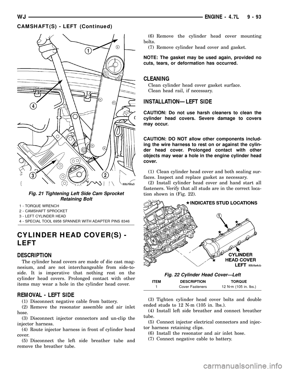
(2) Install cylinder head cover and hand start all
fasteners. Verify that all studs are in the correct loca-
tion shown in (Fig. 22).
(3) Tighten cylinder head cover bolts and double
ended studs to 12 N´m (105 in. lbs.).
(4) Install left side breather and connect breather
tube.
(5) Connect injector electrical connectors and injec-
tor harness retaining clips.
(6) Install the resonator and air inlet hose.
(7) Connect negative cable to battery.
Fig. 21 Tightening Left Side Cam Sprocket
Retaining Bolt
1 - TORQUE WRENCH
2 - CAMSHAFT SPROCKET
3 - LEFT CYLINDER HEAD
4 - SPECIAL TOOL 6958 SPANNER WITH ADAPTER PINS 8346
Fig. 22 Cylinder Head CoverÐLeft
ITEM DESCRIPTION TORQUE
1 Cover Fasteners 12 N´m (105 in. lbs.)
WJENGINE - 4.7L 9 - 93
CAMSHAFT(S) - LEFT (Continued)
Page 1372 of 2199
(5) If the leak is not detected, very slowly turn the
crankshaft and watch for leakage. If a leak is
detected between the crankshaft and seal while
slowly turning the crankshaft, it is possible the
crankshaft seal surface is damaged. The seal area on
the crankshaft could have minor nicks or scratches
that can be polished out with emery cloth.
CAUTION: Use extreme caution when crankshaft
polishing is necessary to remove minor nicks or
scratches. The crankshaft seal flange is specially
machined to complement the function of the rear oil
seal.
(6) For bubbles that remain steady with shaft
rotation, no further inspection can be done until dis-
assembled. (Refer to 9 - ENGINE - DIAGNOSIS AND
TESTING), under the Oil Leak row, for components
inspections on possible causes and corrections.
(7) After the oil leak root cause and appropriate
corrective action have been identified, (Refer to 9 -
ENGINE/ENGINE BLOCK/CRANKSHAFT OIL
SEAL - REAR - REMOVAL).
DIAGNOSIS AND TESTINGÐENGINE OIL LEAK
Begin with a thorough visual inspection of the
engine, particularly at the area of the suspected leak.If an oil leak source is not readily identifiable, the
following steps should be followed:
(1) Do not clean or degrease the engine at this
time because some solvents may cause rubber to
swell, temporarily stopping the leak.
(2) Add an oil soluble dye (use as recommended by
manufacturer). Start the engine and let idle for
approximately 15 minutes. Check the oil dipstick to
make sure the dye is thoroughly mixed as indicated
with a bright yellow color under a black light.
(3) Using a black light, inspect the entire engine
for fluorescent dye, particularly at the suspected area
of oil leak. If the oil leak is found and identified,
repair per service manual instructions.
(4) If dye is not observed, drive the vehicle at var-
ious speeds for approximately 24km (15 miles), and
repeat inspection.If the oil leak source is not pos-
itively identified at this time, proceed with the air
leak detection test method.
Air Leak Detection Test Method
(1) Disconnect the breather cap to air cleaner hose
at the breather cap end. Cap or plug breather cap
nipple.
(2) Remove the PCV valve from the cylinder head
cover. Cap or plug the PCV valve grommet.
(3) Attach an air hose with pressure gauge and
regulator to the dipstick tube.
CAUTION: Do not subject the engine assembly to
more than 20.6 kpa (3 PSI) of test pressure.
(4) Gradually apply air pressure from 1 psi to 2.5
psi maximum while applying soapy water at the sus-
pected source. Adjust the regulator to the suitable
test pressure that provide the best bubbles which
will pinpoint the leak source. If the oil leak is
detected and identified, repair per service manual
procedures.
(5) If the leakage occurs at the rear oil seal area,
refer to the section, Inspection for Rear Seal Area
Leak.
(6) If no leaks are detected, turn off the air supply
and remove the air hose and all plugs and caps.
Install the PCV valve and breather cap hose.
(7) Clean the oil off the suspect oil leak area using
a suitable solvent. Drive the vehicle at various
speeds approximately 24 km (15 miles). Inspect the
engine for signs of an oil leak by using a black light.
INSPECTION FOR REAR SEAL AREA LEAKS
Since it is sometimes difficult to determine the
source of an oil leak in the rear seal area of the
engine, a more involved inspection is necessary. The
following steps should be followed to help pinpoint
the source of the leak.
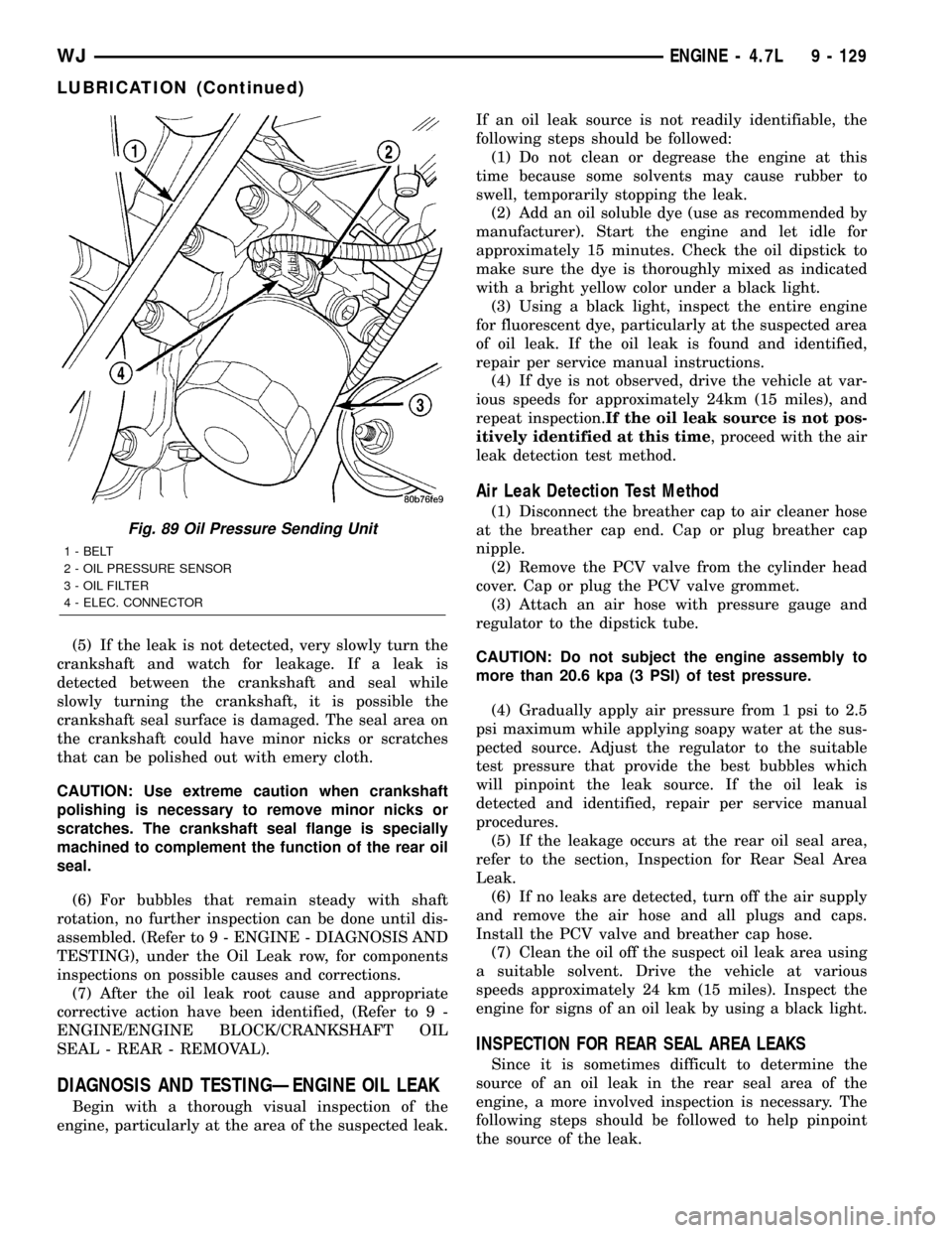
Fig. 89 Oil Pressure Sending Unit
1 - BELT
2 - OIL PRESSURE SENSOR
3 - OIL FILTER
4 - ELEC. CONNECTOR
WJENGINE - 4.7L 9 - 129
LUBRICATION (Continued)
Page 1412 of 2199
FRAME & BUMPERS
TABLE OF CONTENTS
page page
FRONT ABSORBER
REMOVAL.............................1
INSTALLATION..........................1
FRONT FASCIA
REMOVAL.............................1
INSTALLATION..........................1
REAR ABSORBER
REMOVAL.............................2
INSTALLATION..........................2
REAR FASCIA
REMOVAL.............................2
INSTALLATION..........................4
FRAME
SPECIFICATIONS
SPECIFICATIONS - TORQUE.............4
FRAME DIMENSIONS...................4
FRONT SKID PLATE
REMOVAL.............................7INSTALLATION..........................7
FRONT TOW HOOK
REMOVAL.............................7
INSTALLATION..........................7
FUEL TANK SKID PLATE
DESCRIPTION..........................7
REAR TOW HOOK
REMOVAL.............................7
INSTALLATION..........................7
TRAILER HITCH
REMOVAL.............................8
INSTALLATION..........................8
TRANSFER CASE SKID PLATE
REMOVAL.............................8
INSTALLATION..........................8
FRONT ABSORBER
REMOVAL
(1) Remove front fascia, refer to (Refer to 13 -
FRAMES & BUMPERS/BUMPERS/FRONT FASCIA
- REMOVAL).
(2) Remove the retainer attaching the absorber to
the fascia.
(3) Separate the absorber from the fascia.
INSTALLATION
(1) Position the absorber on the fascia.
(2) Install the retainer attaching the absorber to
the fascia.
(3) Install front fascia. Refer to (Refer to 13 -
FRAMES & BUMPERS/BUMPERS/FRONT FASCIA
- INSTALLATION).
FRONT FASCIA
REMOVAL
(1) Raise and support vehicle.
(2) Turn front wheels to access rivets and remove
plastic rivets attaching fascia to wheel liner.
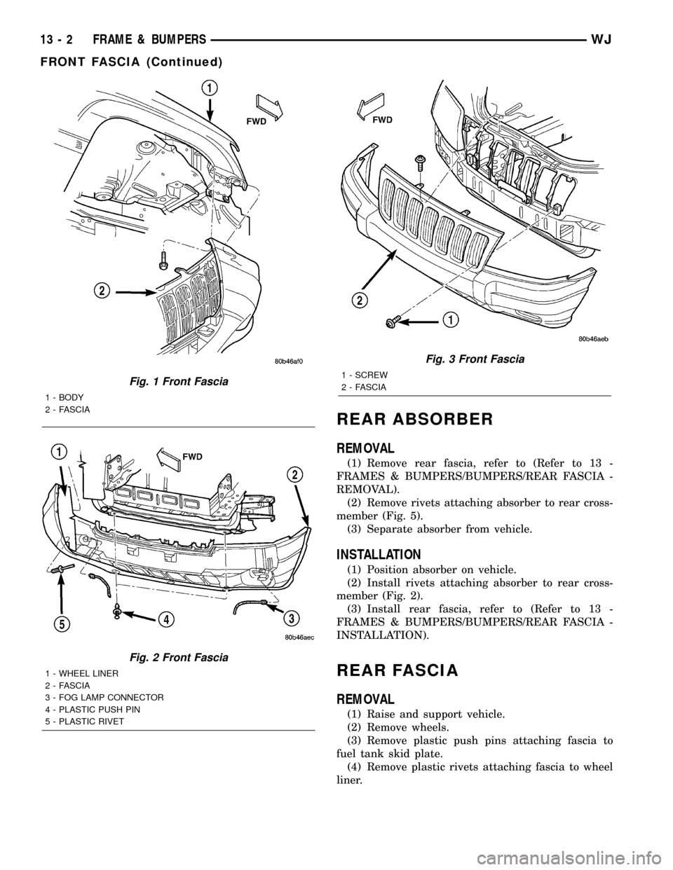
(3) Remove bolts attaching fascia to fender (Fig. 1).(4) Remove plastic push pin fasteners attaching
front fascia to lower radiator crossmember splash
shield (Fig. 2).
(5) Disengage fog lamp connectors, if equipped.
(6) Remove screws attaching fascia/grille to upper
radiator crossmember (Fig. 3).
(7) Slide fascia forward to separate from vehicle.
INSTALLATION
(1) Slide fascia onto vehicle engaging fascia with
tabs on bottom of front fenders.
(2) Install screws attaching fascia/grille to upper
radiator crossmember (Fig. 3).
(3) Install bolts attaching fascia to fender (Fig. 1).
(4) Engage fog lamp connectors, if equipped.
(5) Install plastic rivets attaching fascia to wheel
liner.
(6) Install plastic push pin fasteners attaching
front fascia to lower radiator crossmember splash
shield (Fig. 2).
(7) Remove supports and lower vehicle.
WJFRAME & BUMPERS 13 - 1
Page 1413 of 2199
REAR ABSORBER
REMOVAL
(1) Remove rear fascia, refer to (Refer to 13 -
FRAMES & BUMPERS/BUMPERS/REAR FASCIA -
REMOVAL).
(2) Remove rivets attaching absorber to rear cross-
member (Fig. 5).
(3) Separate absorber from vehicle.
INSTALLATION
(1) Position absorber on vehicle.
(2) Install rivets attaching absorber to rear cross-
member (Fig. 2).
(3) Install rear fascia, refer to (Refer to 13 -
FRAMES & BUMPERS/BUMPERS/REAR FASCIA -
INSTALLATION).
REAR FASCIA
REMOVAL
(1) Raise and support vehicle.
(2) Remove wheels.
(3) Remove plastic push pins attaching fascia to
fuel tank skid plate.
(4) Remove plastic rivets attaching fascia to wheel
liner.
Fig. 1 Front Fascia
1 - BODY
2 - FASCIA
Fig. 2 Front Fascia
1 - WHEEL LINER
2 - FASCIA
3 - FOG LAMP CONNECTOR
4 - PLASTIC PUSH PIN
5 - PLASTIC RIVET
Fig. 3 Front Fascia
1 - SCREW
2 - FASCIA
13 - 2 FRAME & BUMPERSWJ
FRONT FASCIA (Continued)