lamp JEEP GRAND CHEROKEE 2003 WJ / 2.G Workshop Manual
[x] Cancel search | Manufacturer: JEEP, Model Year: 2003, Model line: GRAND CHEROKEE, Model: JEEP GRAND CHEROKEE 2003 WJ / 2.GPages: 2199, PDF Size: 76.01 MB
Page 1167 of 2199
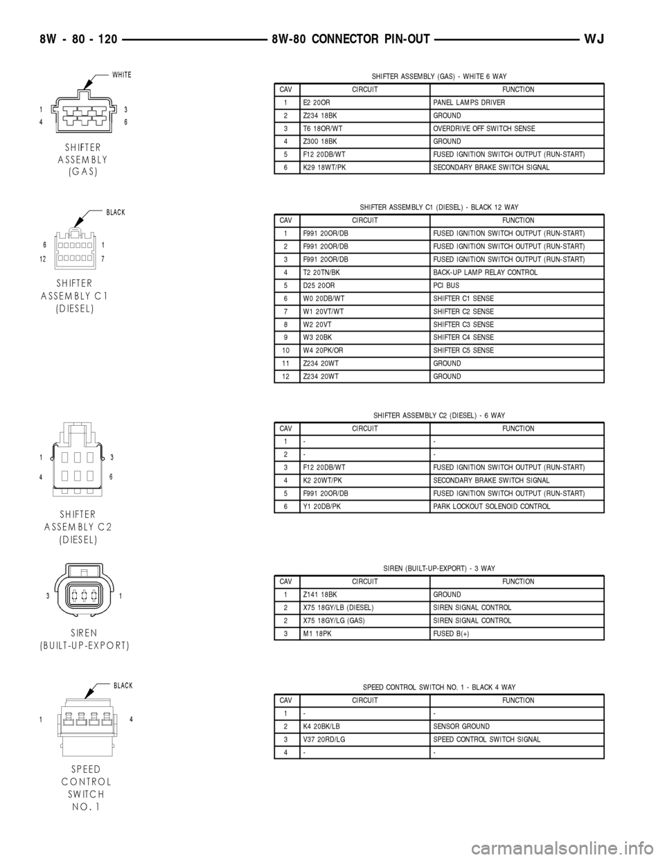
SHIFTER ASSEMBLY (GAS) - WHITE 6 WAY
CAV CIRCUIT FUNCTION
1 E2 20OR PANEL LAMPS DRIVER
2 Z234 18BK GROUND
3 T6 18OR/WT OVERDRIVE OFF SWITCH SENSE
4 Z300 18BK GROUND
5 F12 20DB/WT FUSED IGNITION SWITCH OUTPUT (RUN-START)
6 K29 18WT/PK SECONDARY BRAKE SWITCH SIGNAL
SHIFTER ASSEMBLY C1 (DIESEL) - BLACK 12 WAY
CAV CIRCUIT FUNCTION
1 F991 20OR/DB FUSED IGNITION SWITCH OUTPUT (RUN-START)
2 F991 20OR/DB FUSED IGNITION SWITCH OUTPUT (RUN-START)
3 F991 20OR/DB FUSED IGNITION SWITCH OUTPUT (RUN-START)
4 T2 20TN/BK BACK-UP LAMP RELAY CONTROL
5 D25 20OR PCI BUS
6 W0 20DB/WT SHIFTER C1 SENSE
7 W1 20VT/WT SHIFTER C2 SENSE
8 W2 20VT SHIFTER C3 SENSE
9 W3 20BK SHIFTER C4 SENSE
10 W4 20PK/OR SHIFTER C5 SENSE
11 Z234 20WT GROUND
12 Z234 20WT GROUND
SHIFTER ASSEMBLY C2 (DIESEL)-6WAY
CAV CIRCUIT FUNCTION
1- -
2- -
3 F12 20DB/WT FUSED IGNITION SWITCH OUTPUT (RUN-START)
4 K2 20WT/PK SECONDARY BRAKE SWITCH SIGNAL
5 F991 20OR/DB FUSED IGNITION SWITCH OUTPUT (RUN-START)
6 Y1 20DB/PK PARK LOCKOUT SOLENOID CONTROL
SIREN (BUILT-UP-EXPORT)-3WAY
CAV CIRCUIT FUNCTION
1 Z141 18BK GROUND
2 X75 18GY/LB (DIESEL) SIREN SIGNAL CONTROL
2 X75 18GY/LG (GAS) SIREN SIGNAL CONTROL
3 M1 18PK FUSED B(+)
SPEED CONTROL SWITCH NO. 1 - BLACK 4 WAY
CAV CIRCUIT FUNCTION
1- -
2 K4 20BK/LB SENSOR GROUND
3 V37 20RD/LG SPEED CONTROL SWITCH SIGNAL
4- -
8W - 80 - 120 8W-80 CONNECTOR PIN-OUTWJ
Page 1169 of 2199
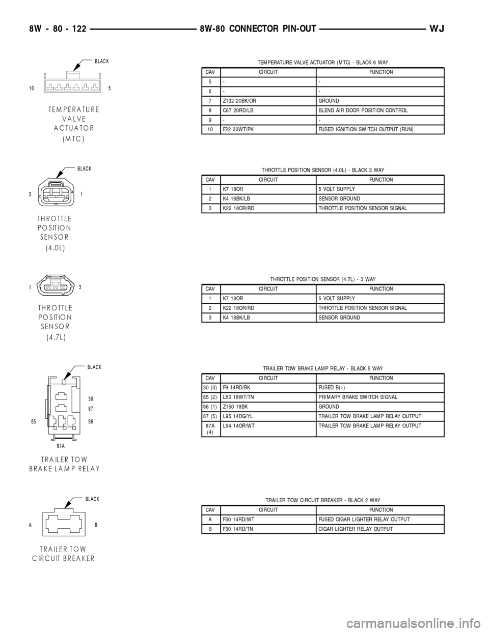
TEMPERATURE VALVE ACTUATOR (MTC) - BLACK 6 WAY
CAV CIRCUIT FUNCTION
5- -
6- -
7 Z132 20BK/OR GROUND
8 C67 20RD/LB BLEND AIR DOOR POSITION CONTROL
9- -
10 F22 20WT/PK FUSED IGNITION SWITCH OUTPUT (RUN)
THROTTLE POSITION SENSOR (4.0L) - BLACK 3 WAY
CAV CIRCUIT FUNCTION
1 K7 18OR 5 VOLT SUPPLY
2 K4 18BK/LB SENSOR GROUND
3 K22 18OR/RD THROTTLE POSITION SENSOR SIGNAL
THROTTLE POSITION SENSOR (4.7L)-3WAY
CAV CIRCUIT FUNCTION
1 K7 18OR 5 VOLT SUPPLY
2 K22 18OR/RD THROTTLE POSITION SENSOR SIGNAL
3 K4 18BK/LB SENSOR GROUND
TRAILER TOW BRAKE LAMP RELAY - BLACK 5 WAY
CAV CIRCUIT FUNCTION
30 (3) F9 14RD/BK FUSED B(+)
85 (2) L50 18WT/TN PRIMARY BRAKE SWITCH SIGNAL
86 (1) Z150 18BK GROUND
87 (5) L95 14DG/YL TRAILER TOW BRAKE LAMP RELAY OUTPUT
87A
(4)L94 14OR/WT TRAILER TOW BRAKE LAMP RELAY OUTPUT
TRAILER TOW CIRCUIT BREAKER - BLACK 2 WAY
CAV CIRCUIT FUNCTION
A F30 14RD/WT FUSED CIGAR LIGHTER RELAY OUTPUT
B F30 14RD/TN CIGAR LIGHTER RELAY OUTPUT
8W - 80 - 122 8W-80 CONNECTOR PIN-OUTWJ
Page 1170 of 2199
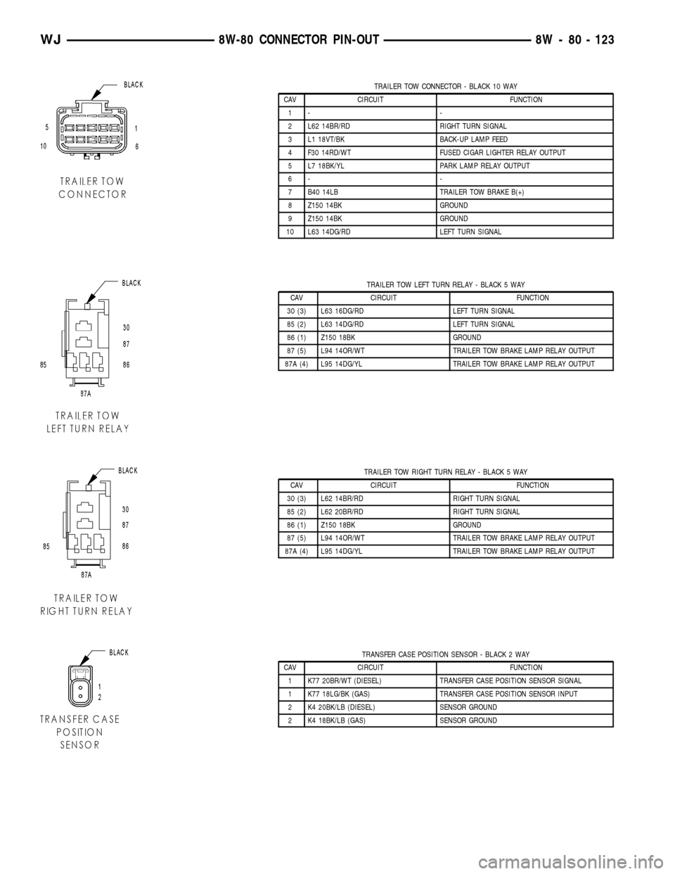
TRAILER TOW CONNECTOR - BLACK 10 WAY
CAV CIRCUIT FUNCTION
1- -
2 L62 14BR/RD RIGHT TURN SIGNAL
3 L1 18VT/BK BACK-UP LAMP FEED
4 F30 14RD/WT FUSED CIGAR LIGHTER RELAY OUTPUT
5 L7 18BK/YL PARK LAMP RELAY OUTPUT
6- -
7 B40 14LB TRAILER TOW BRAKE B(+)
8 Z150 14BK GROUND
9 Z150 14BK GROUND
10 L63 14DG/RD LEFT TURN SIGNAL
TRAILER TOW LEFT TURN RELAY - BLACK 5 WAY
CAV CIRCUIT FUNCTION
30 (3) L63 16DG/RD LEFT TURN SIGNAL
85 (2) L63 14DG/RD LEFT TURN SIGNAL
86 (1) Z150 18BK GROUND
87 (5) L94 14OR/WT TRAILER TOW BRAKE LAMP RELAY OUTPUT
87A (4) L95 14DG/YL TRAILER TOW BRAKE LAMP RELAY OUTPUT
TRAILER TOW RIGHT TURN RELAY - BLACK 5 WAY
CAV CIRCUIT FUNCTION
30 (3) L62 14BR/RD RIGHT TURN SIGNAL
85 (2) L62 20BR/RD RIGHT TURN SIGNAL
86 (1) Z150 18BK GROUND
87 (5) L94 14OR/WT TRAILER TOW BRAKE LAMP RELAY OUTPUT
87A (4) L95 14DG/YL TRAILER TOW BRAKE LAMP RELAY OUTPUT
TRANSFER CASE POSITION SENSOR - BLACK 2 WAY
CAV CIRCUIT FUNCTION
1 K77 20BR/WT (DIESEL) TRANSFER CASE POSITION SENSOR SIGNAL
1 K77 18LG/BK (GAS) TRANSFER CASE POSITION SENSOR INPUT
2 K4 20BK/LB (DIESEL) SENSOR GROUND
2 K4 18BK/LB (GAS) SENSOR GROUND
WJ8W-80 CONNECTOR PIN-OUT 8W - 80 - 123
Page 1173 of 2199
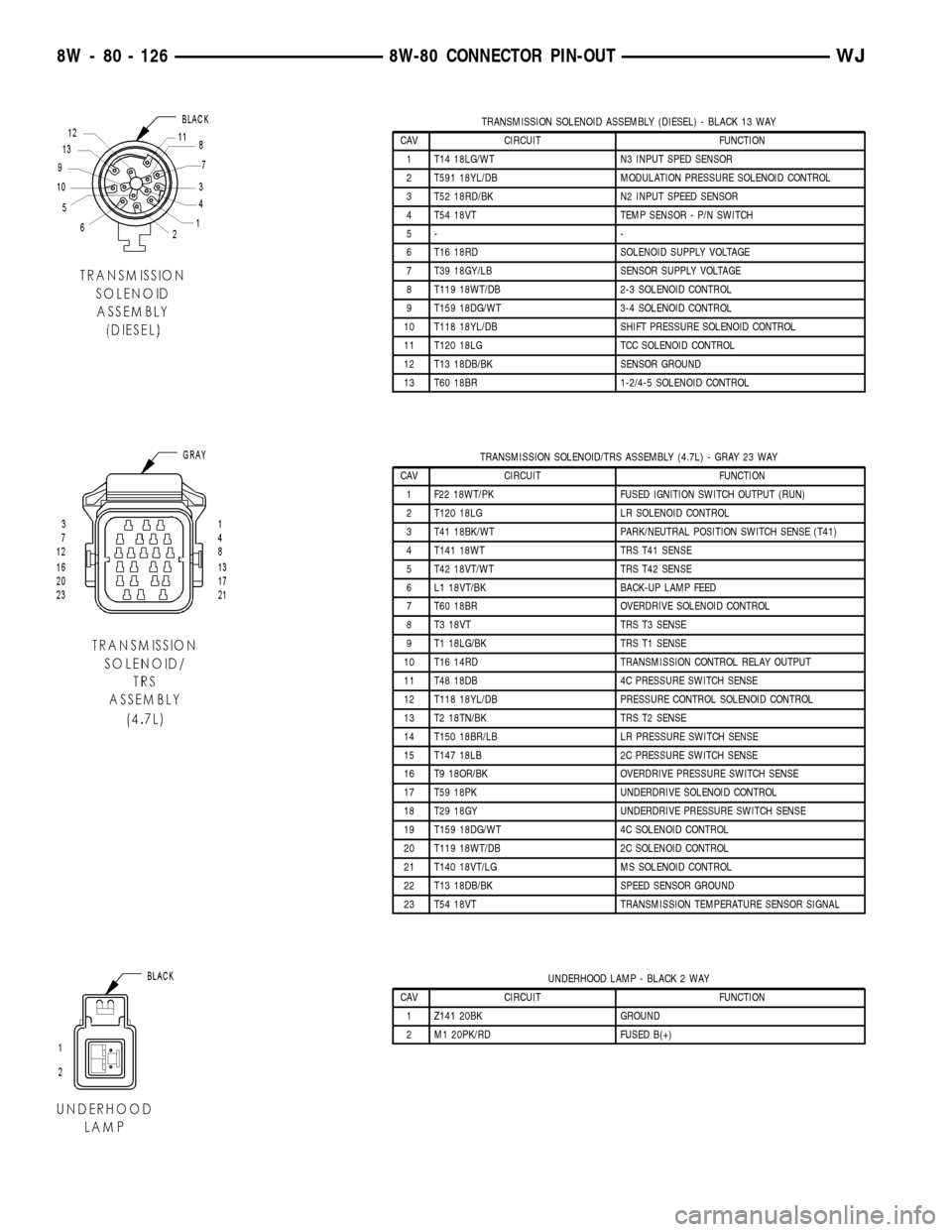
TRANSMISSION SOLENOID ASSEMBLY (DIESEL) - BLACK 13 WAY
CAV CIRCUIT FUNCTION
1 T14 18LG/WT N3 INPUT SPED SENSOR
2 T591 18YL/DB MODULATION PRESSURE SOLENOID CONTROL
3 T52 18RD/BK N2 INPUT SPEED SENSOR
4 T54 18VT TEMP SENSOR - P/N SWITCH
5- -
6 T16 18RD SOLENOID SUPPLY VOLTAGE
7 T39 18GY/LB SENSOR SUPPLY VOLTAGE
8 T119 18WT/DB 2-3 SOLENOID CONTROL
9 T159 18DG/WT 3-4 SOLENOID CONTROL
10 T118 18YL/DB SHIFT PRESSURE SOLENOID CONTROL
11 T120 18LG TCC SOLENOID CONTROL
12 T13 18DB/BK SENSOR GROUND
13 T60 18BR 1-2/4-5 SOLENOID CONTROL
TRANSMISSION SOLENOID/TRS ASSEMBLY (4.7L) - GRAY 23 WAY
CAV CIRCUIT FUNCTION
1 F22 18WT/PK FUSED IGNITION SWITCH OUTPUT (RUN)
2 T120 18LG LR SOLENOID CONTROL
3 T41 18BK/WT PARK/NEUTRAL POSITION SWITCH SENSE (T41)
4 T141 18WT TRS T41 SENSE
5 T42 18VT/WT TRS T42 SENSE
6 L1 18VT/BK BACK-UP LAMP FEED
7 T60 18BR OVERDRIVE SOLENOID CONTROL
8 T3 18VT TRS T3 SENSE
9 T1 18LG/BK TRS T1 SENSE
10 T16 14RD TRANSMISSION CONTROL RELAY OUTPUT
11 T48 18DB 4C PRESSURE SWITCH SENSE
12 T118 18YL/DB PRESSURE CONTROL SOLENOID CONTROL
13 T2 18TN/BK TRS T2 SENSE
14 T150 18BR/LB LR PRESSURE SWITCH SENSE
15 T147 18LB 2C PRESSURE SWITCH SENSE
16 T9 18OR/BK OVERDRIVE PRESSURE SWITCH SENSE
17 T59 18PK UNDERDRIVE SOLENOID CONTROL
18 T29 18GY UNDERDRIVE PRESSURE SWITCH SENSE
19 T159 18DG/WT 4C SOLENOID CONTROL
20 T119 18WT/DB 2C SOLENOID CONTROL
21 T140 18VT/LG MS SOLENOID CONTROL
22 T13 18DB/BK SPEED SENSOR GROUND
23 T54 18VT TRANSMISSION TEMPERATURE SENSOR SIGNAL
UNDERHOOD LAMP - BLACK 2 WAY
CAV CIRCUIT FUNCTION
1 Z141 20BK GROUND
2 M1 20PK/RD FUSED B(+)
8W - 80 - 126 8W-80 CONNECTOR PIN-OUTWJ
Page 1176 of 2199
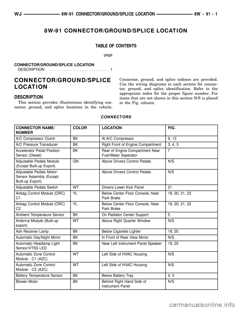
8W-91 CONNECTOR/GROUND/SPLICE LOCATION
TABLE OF CONTENTS
page
CONNECTOR/GROUND/SPLICE LOCATION
DESCRIPTION..........................1
CONNECTOR/GROUND/SPLICE
LOCATION
DESCRIPTION
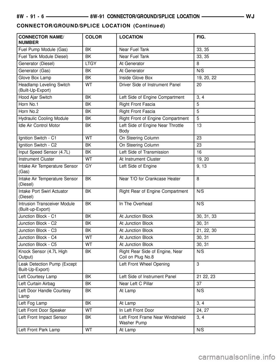
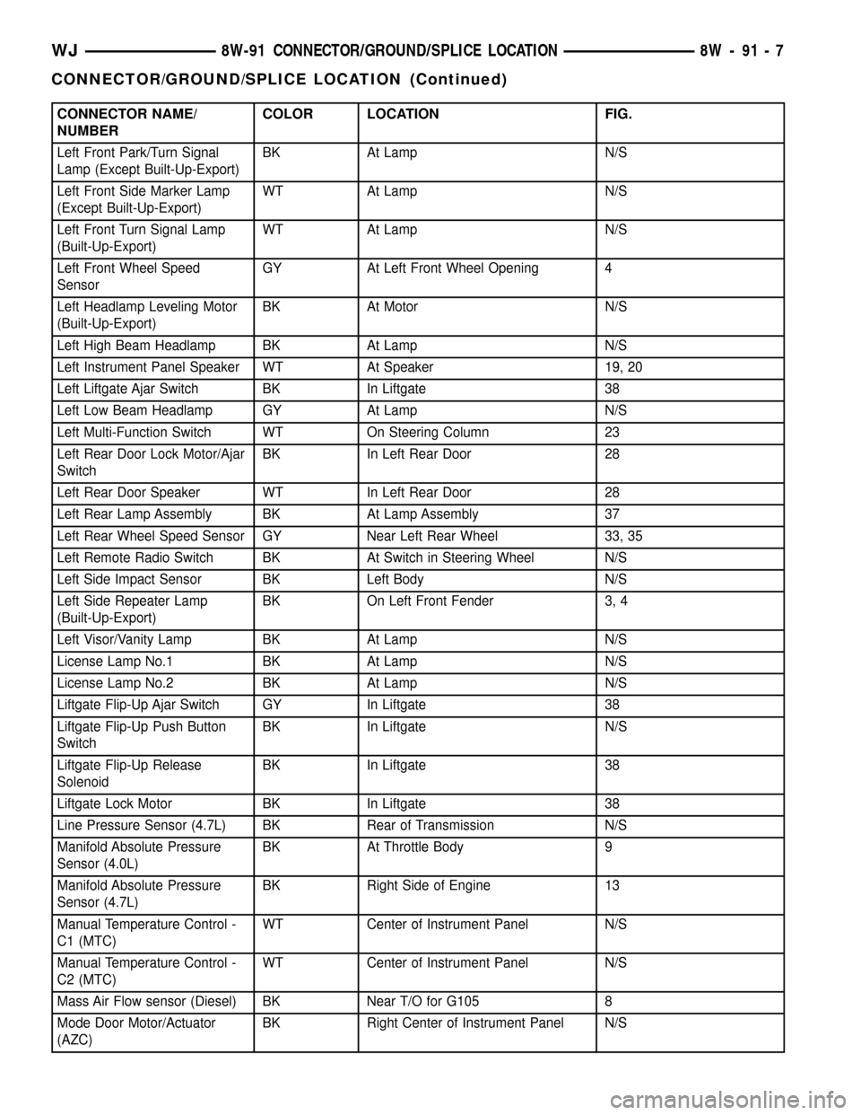
This section provides illustrations identifying con-
nector, ground, and splice locations in the vehicle.Connector, ground, and splice indexes are provided.
Use the wiring diagrams in each section for connec-
tor, ground, and splice identification. Refer to the
appropriate index for the proper figure number. For
items that are not shown in this section N/S is placed
in the Fig. column.
CONNECTORS
CONNECTOR NAME/
NUMBERCOLOR LOCATION FIG.
A/C Compressor Clutch BK At A/C Compressor 9, 13
A/C Pressure Transducer BK Right Front of Engine Compartment 3, 4, 5
Accelerator Pedal Position
Sensor (Diesel)BK Rear of Engine Compartment Near
Fuel/Water Seperator7
Adjustable Pedals Module
(Except Built-up Export)GN Above Drivers Control Pedals N/S
Adjustable Pedals Motor/
Sensor Assembly (Except
Built-up Export)Above Drivers Control Pedals N/S
Adjustable Pedals Switch WT Drivers Lower Kick Panel 21
Airbag Control Module (ORC)
C1YL Below Center Floor Console, Near
Park Brake19, 20, 21, 22
Airbag Control Module (ORC)
C2YL Below Center Floor Console, Near
Park Brake19, 20, 21, 22
Ambient Temperature Sensor BK On Radiator Center Support 5
Antenna Module (Built-up-
export)WT Above Right Quarter Window N/S
Ash Receiver Lamp BK Below Cigarette Lighter 19, 20
Automatic Day/Night Mirror BK In Front of Rear View Mirror N/S
Automatic Headlamp Light
Sensor/VTSS LEDBK Near Left Instrument Panel Speaker 19, 20
Automatic Zone Control
Module - C1 (AZC)WT Left Side of HVAC Housing N/S
Automatic Zone Control
Module - C2 (AZC)WT Left Side of HVAC Housing N/S
Battery Temperature Sensor BK Below Battery Tray 4, 5
Blower Motor BK Behind Right Hand Side of
Instrument PanelN/S
WJ8W-91 CONNECTOR/GROUND/SPLICE LOCATION 8W - 91 - 1
Page 1177 of 2199
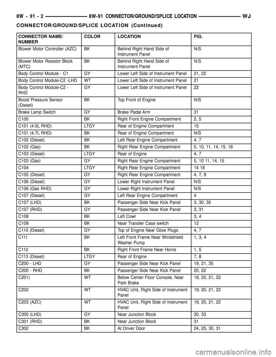
CONNECTOR NAME/
NUMBERCOLOR LOCATION FIG.
Blower Motor Controller (AZC) BK Behind Right Hand Side of
Instrument PanelN/S
Blower Motor Resistor Block
(MTC)BK Behind Right Hand Side of
Instrument PanelN/S
Body Control Module - C1 GY Lower Left Side of Instrument Panel 21, 22
Body Control Module-C2 -LHD WT Lower Left Side of Instrument Panel 21
Body Control Module-C2 -
RHDGY Lower Left Side of Instrument Panel 22
Boost Pressure Sensor
(Diesel)BK Top Front of Engine N/S
Brake Lamp Switch GY Brake Pedal Arm 31
C100 BK Right Front Engine Compartment 2, 5
C101 (4.0L RHD) LTGY Rear of Engine Compartment 15
C101 (4.7L RHD) BK Rear of Engine Compartment N/S
C102 (Diesel) BK Left Rear Engine Compartment 4, 7
C102 (Gas) BK Right Rear Engine Compartment 5, 10, 11, 14, 15, 18
C103 (Diesel) LTGY Rear of Engine 4, 7
C103 (Gas) GY Right Rear Engine Compartment 5, 10 11, 14, 15
C104 LTGY Right Rear Engine Compartment 14 18
C105 (Diesel) GY Right Rear Engine Compartment 4, 7, 8
C106 (Diesel) GY Lower Right Instrument Panel N/S
C106 (Gas RHD) GY Lower Right Instrument Panel N/S
C107 (Diesel) GY Left Rear Engine Compartment 4
C107 (LHD) BK Passenger Side Near Kick Panel 3, 30, 35
C107 (RHD) GY Passenger Side Near Kick Panel 3, 31
C108 BK Left Cowl 3, 4
C109 BK Near Transfer Case switch 12
C110 (Diesel) GY Top of Engine Near Glow Plugs 4, 7
C111 BK Left Front Frame Near Windshield
Washer Pump1, 3, 4
C112 BK Right Front Frame Near Horns 1, 5
C113 (Diesel) LTGY Rear of Engine 7, 8
C200 - LHD GY Passenger Side Near Kick Panel 19, 21, 35
C200 - RHD BK Passenger Side Near Kick Panel 20, 22
C201) WT Below Center Floor Console, Near
Park Brake19, 20, 21, 22
C202 WT HVAC Unit, Right Side of Instrument
Panel19, 20, 21, 22
C203 (AZC) WT HVAC Unit, Right Side of Instrument
Panel19, 20, 21, 22
C300 (LHD) GY Near Junction Block 30, 33
C301 (RHD) BK Near Junction Block 31
C302 BK At Driver Door 24, 25, 30, 31
8W - 91 - 2 8W-91 CONNECTOR/GROUND/SPLICE LOCATIONWJ
CONNECTOR/GROUND/SPLICE LOCATION (Continued)
Page 1178 of 2199
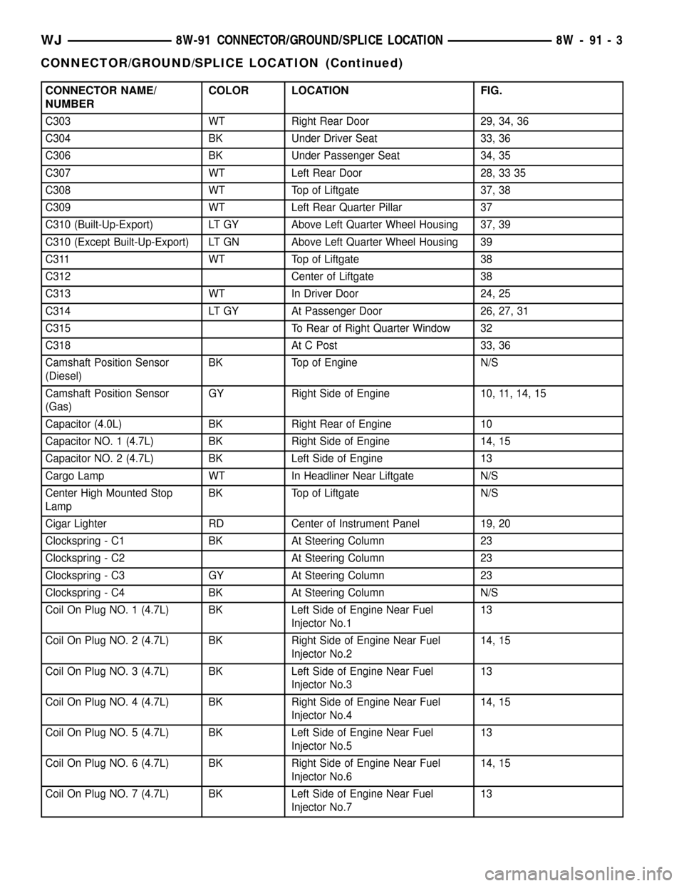
CONNECTOR NAME/
NUMBERCOLOR LOCATION FIG.
C303 WT Right Rear Door 29, 34, 36
C304 BK Under Driver Seat 33, 36
C306 BK Under Passenger Seat 34, 35
C307 WT Left Rear Door 28, 33 35
C308 WT Top of Liftgate 37, 38
C309 WT Left Rear Quarter Pillar 37
C310 (Built-Up-Export) LT GY Above Left Quarter Wheel Housing 37, 39
C310 (Except Built-Up-Export) LT GN Above Left Quarter Wheel Housing 39
C311 WT Top of Liftgate 38
C312 Center of Liftgate 38
C313 WT In Driver Door 24, 25
C314 LT GY At Passenger Door 26, 27, 31
C315 To Rear of Right Quarter Window 32
C318 At C Post 33, 36
Camshaft Position Sensor
(Diesel)BK Top of Engine N/S
Camshaft Position Sensor
(Gas)GY Right Side of Engine 10, 11, 14, 15
Capacitor (4.0L) BK Right Rear of Engine 10
Capacitor NO. 1 (4.7L) BK Right Side of Engine 14, 15
Capacitor NO. 2 (4.7L) BK Left Side of Engine 13
Cargo Lamp WT In Headliner Near Liftgate N/S
Center High Mounted Stop
LampBK Top of Liftgate N/S
Cigar Lighter RD Center of Instrument Panel 19, 20
Clockspring - C1 BK At Steering Column 23
Clockspring - C2 At Steering Column 23
Clockspring - C3 GY At Steering Column 23
Clockspring - C4 BK At Steering Column N/S
Coil On Plug NO. 1 (4.7L) BK Left Side of Engine Near Fuel
Injector No.113
Coil On Plug NO. 2 (4.7L) BK Right Side of Engine Near Fuel
Injector No.214, 15
Coil On Plug NO. 3 (4.7L) BK Left Side of Engine Near Fuel
Injector No.313
Coil On Plug NO. 4 (4.7L) BK Right Side of Engine Near Fuel
Injector No.414, 15
Coil On Plug NO. 5 (4.7L) BK Left Side of Engine Near Fuel
Injector No.513
Coil On Plug NO. 6 (4.7L) BK Right Side of Engine Near Fuel
Injector No.614, 15
Coil On Plug NO. 7 (4.7L) BK Left Side of Engine Near Fuel
Injector No.713
WJ8W-91 CONNECTOR/GROUND/SPLICE LOCATION 8W - 91 - 3
CONNECTOR/GROUND/SPLICE LOCATION (Continued)
Page 1179 of 2199
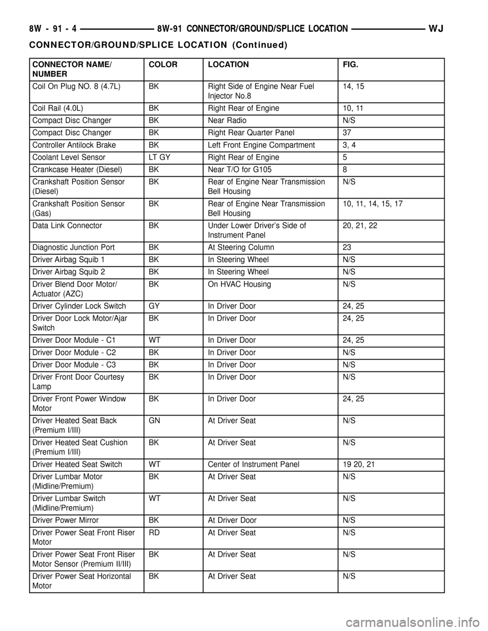
CONNECTOR NAME/
NUMBERCOLOR LOCATION FIG.
Coil On Plug NO. 8 (4.7L) BK Right Side of Engine Near Fuel
Injector No.814, 15
Coil Rail (4.0L) BK Right Rear of Engine 10, 11
Compact Disc Changer BK Near Radio N/S
Compact Disc Changer BK Right Rear Quarter Panel 37
Controller Antilock Brake BK Left Front Engine Compartment 3, 4
Coolant Level Sensor LT GY Right Rear of Engine 5
Crankcase Heater (Diesel) BK Near T/O for G105 8
Crankshaft Position Sensor
(Diesel)BK Rear of Engine Near Transmission
Bell HousingN/S
Crankshaft Position Sensor
(Gas)BK Rear of Engine Near Transmission
Bell Housing10, 11, 14, 15, 17
Data Link Connector BK Under Lower Driver's Side of
Instrument Panel20, 21, 22
Diagnostic Junction Port BK At Steering Column 23
Driver Airbag Squib 1 BK In Steering Wheel N/S
Driver Airbag Squib 2 BK In Steering Wheel N/S
Driver Blend Door Motor/
Actuator (AZC)BK On HVAC Housing N/S
Driver Cylinder Lock Switch GY In Driver Door 24, 25
Driver Door Lock Motor/Ajar
SwitchBK In Driver Door 24, 25
Driver Door Module - C1 WT In Driver Door 24, 25
Driver Door Module - C2 BK In Driver Door N/S
Driver Door Module - C3 BK In Driver Door N/S
Driver Front Door Courtesy
LampBK In Driver Door N/S
Driver Front Power Window
MotorBK In Driver Door 24, 25
Driver Heated Seat Back
(Premium I/III)GN At Driver Seat N/S
Driver Heated Seat Cushion
(Premium I/III)BK At Driver Seat N/S
Driver Heated Seat Switch WT Center of Instrument Panel 19 20, 21
Driver Lumbar Motor
(Midline/Premium)BK At Driver Seat N/S
Driver Lumbar Switch
(Midline/Premium)WT At Driver Seat N/S
Driver Power Mirror BK At Driver Door N/S
Driver Power Seat Front Riser
MotorRD At Driver Seat N/S
Driver Power Seat Front Riser
Motor Sensor (Premium II/III)BK At Driver Seat N/S
Driver Power Seat Horizontal
MotorBK At Driver Seat N/S
8W - 91 - 4 8W-91 CONNECTOR/GROUND/SPLICE LOCATIONWJ
CONNECTOR/GROUND/SPLICE LOCATION (Continued)
Page 1181 of 2199
CONNECTOR NAME/
NUMBERCOLOR LOCATION FIG.
Fuel Pump Module (Gas) BK Near Fuel Tank 33, 35
Fuel Tank Module Diesel) BK Near Fuel Tank 33, 35
Generator (Diesel) LTGY At Generator 8
Generator (Gas) BK At Generator N/S
Glove Box Lamp BK Inside Glove Box 19, 20, 22
Headlamp Leveling Switch
(Built-Up-Export)WT Driver Side of Instrument Panel 20
Hood Ajar Switch BK Left Side of Engine Compartment 3, 4
Horn No.1 BK Right Front Fascia 5
Horn No.2 BK Right Front Fascia 5
Hydraulic Cooling Module BK Right Front of Engine Compartment 5
Idle Air Control Motor BK Left Side of Engine Near Throttle
Body13
Ignition Switch - C1 WT On Steering Column 23
Ignition Switch - C2 BK On Steering Column 23
Input Speed Sensor (4.7L) BK Left Side of Transmission 16
Instrument Cluster WT At Instrument Cluster 19, 20
Intake Air Temperature Sensor
(Gas)GY Left Side of Engine 9, 13
Intake Air Temperature Sensor
(Diesel)BK Near T/O for Crankcase Heater 8
Intake Port Swirl Actuator
(Diesel)BK Right Rear of Engine Compartment N/S
Intrusion Transceiver Module
(Built-up-Export)BK In The Overhead N/S
Junction Block - C1 BK At Junction Block 30, 31, 33
Junction Block - C2 BK At Junction Block 30, 31
Junction Block - C3 BK At Junction Block 21, 22, 30
Junction Block - C4 WT At Junction Block 30, 31
Junction Block - C5 WT At Junction Block 30, 31
Knock Sensor (4.7L High
Output)BK Right Rear Side of Engine, Near
Coil on Plug No.8N/S
Leak Detection Pump (Except
Built-Up-Export)Left Front Wheel Opening 3
Left Courtesy Lamp BK Left Side of Instrument Panel 21 22, 23
Left Curtain Airbag BK Near Left C Pillar 37
Left Door Handle Courtesy
LampBK At Lamp N/S
Left Fog Lamp BK At Lamp 3, 4
Left Front Door Speaker WT In Left Front Door 24, 27
Left Front Impact Sensor BK Left Front Frame Near Windshield
Washer Pump3, 4
Left Front Park Lamp WT At Lamp N/S
8W - 91 - 6 8W-91 CONNECTOR/GROUND/SPLICE LOCATIONWJ
CONNECTOR/GROUND/SPLICE LOCATION (Continued)
Page 1182 of 2199
CONNECTOR NAME/
NUMBERCOLOR LOCATION FIG.
Left Front Park/Turn Signal
Lamp (Except Built-Up-Export)BK At Lamp N/S
Left Front Side Marker Lamp
(Except Built-Up-Export)WT At Lamp N/S
Left Front Turn Signal Lamp
(Built-Up-Export)WT At Lamp N/S
Left Front Wheel Speed
SensorGY At Left Front Wheel Opening 4
Left Headlamp Leveling Motor
(Built-Up-Export)BK At Motor N/S
Left High Beam Headlamp BK At Lamp N/S
Left Instrument Panel Speaker WT At Speaker 19, 20
Left Liftgate Ajar Switch BK In Liftgate 38
Left Low Beam Headlamp GY At Lamp N/S
Left Multi-Function Switch WT On Steering Column 23
Left Rear Door Lock Motor/Ajar
SwitchBK In Left Rear Door 28
Left Rear Door Speaker WT In Left Rear Door 28
Left Rear Lamp Assembly BK At Lamp Assembly 37
Left Rear Wheel Speed Sensor GY Near Left Rear Wheel 33, 35
Left Remote Radio Switch BK At Switch in Steering Wheel N/S
Left Side Impact Sensor BK Left Body N/S
Left Side Repeater Lamp
(Built-Up-Export)BK On Left Front Fender 3, 4
Left Visor/Vanity Lamp BK At Lamp N/S
License Lamp No.1 BK At Lamp N/S
License Lamp No.2 BK At Lamp N/S
Liftgate Flip-Up Ajar Switch GY In Liftgate 38
Liftgate Flip-Up Push Button
SwitchBK In Liftgate N/S
Liftgate Flip-Up Release
SolenoidBK In Liftgate 38
Liftgate Lock Motor BK In Liftgate 38
Line Pressure Sensor (4.7L) BK Rear of Transmission N/S
Manifold Absolute Pressure
Sensor (4.0L)BK At Throttle Body 9
Manifold Absolute Pressure
Sensor (4.7L)BK Right Side of Engine 13
Manual Temperature Control -
C1 (MTC)WT Center of Instrument Panel N/S
Manual Temperature Control -
C2 (MTC)WT Center of Instrument Panel N/S
Mass Air Flow sensor (Diesel) BK Near T/O for G105 8
Mode Door Motor/Actuator
(AZC)BK Right Center of Instrument Panel N/S
WJ8W-91 CONNECTOR/GROUND/SPLICE LOCATION 8W - 91 - 7
CONNECTOR/GROUND/SPLICE LOCATION (Continued)