Fill location JEEP GRAND CHEROKEE 2003 WJ / 2.G Owner's Manual
[x] Cancel search | Manufacturer: JEEP, Model Year: 2003, Model line: GRAND CHEROKEE, Model: JEEP GRAND CHEROKEE 2003 WJ / 2.GPages: 2199, PDF Size: 76.01 MB
Page 1435 of 2199

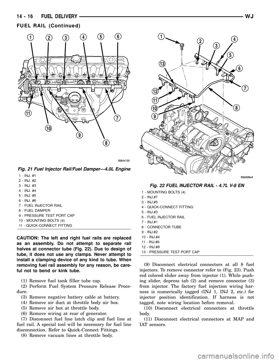
CAUTION: The left and right fuel rails are replaced
as an assembly. Do not attempt to separate rail
halves at connector tube (Fig. 22). Due to design of
tube, it does not use any clamps. Never attempt to
install a clamping device of any kind to tube. When
removing fuel rail assembly for any reason, be care-
ful not to bend or kink tube.
(1) Remove fuel tank filler tube cap.
(2) Perform Fuel System Pressure Release Proce-
dure.
(3) Remove negative battery cable at battery.
(4) Remove air duct at throttle body air box.
(5) Remove air box at throttle body.
(6) Remove wiring at rear of generator.
(7) Disconnect fuel line latch clip and fuel line at
fuel rail. A special tool will be necessary for fuel line
disconnection. Refer to Quick-Connect Fittings.
(8) Remove vacuum lines at throttle body.(9) Disconnect electrical connectors at all 8 fuel
injectors. To remove connector refer to (Fig. 23). Push
red colored slider away from injector (1). While push-
ing slider, depress tab (2) and remove connector (3)
from injector. The factory fuel injection wiring har-
ness is numerically tagged (INJ 1, INJ 2, etc.) for
injector position identification. If harness is not
tagged, note wiring location before removal.
(10) Disconnect electrical connectors at throttle
body.
(11) Disconnect electrical connectors at MAP and
IAT sensors.
Fig. 21 Fuel Injector Rail/Fuel DamperÐ4.0L Engine
1 - INJ. #1
2 - INJ. #2
3 - INJ. #3
4 - INJ. #4
5 - INJ. #5
6 - INJ. #6
7 - FUEL INJECTOR RAIL
8 - FUEL DAMPER
9 - PRESSURE TEST PORT CAP
10 - MOUNTING BOLTS (4)
11 - QUICK-CONNECT FITTING
Fig. 22 FUEL INJECTOR RAIL - 4.7L V-8 EN
1 - MOUNTING BOLTS (4)
2 - INJ.#7
3 - INJ.#5
4 - QUICK-CONNECT FITTING
5 - INJ.#3
6 - FUEL INJECTOR RAIL
7 - INJ.#1
8 - CONNECTOR TUBE
9 - INJ.#2
10 - INJ.#4
11 - INJ.#6
12 - INJ.#8
13 - PRESSURE TEST PORT CAP
14 - 16 FUEL DELIVERYWJ
FUEL RAIL (Continued)
Page 1436 of 2199

(12) Remove first three ignition coils on each bank
(cylinders #1, 3, 5, 2, 4 and 6). Refer to Ignition Coil
Removal/Installation.
(13) Remove 4 fuel rail mounting bolts (Fig. 22).
(14) Gently rock and pullleftside of fuel rail until
fuel injectors just start to clear machined holes in
cylinder head. Gently rock and pullrightside of rail
until injectors just start to clear cylinder head holes.
Repeat this procedure (left/right) until all injectors
have cleared cylinder head holes.
(15) Remove fuel rail (with injectors attached)
from engine.
(16) If fuel injectors are to be removed, refer to
Fuel Injector Removal/Installation.
REMOVAL - 4.0L
The fuel damper is not serviced separately.
WARNING: THE FUEL SYSTEM IS UNDER CON-
STANT FUEL PRESSURE EVEN WITH ENGINE OFF.
THIS PRESSURE MUST BE RELEASED BEFORE
SERVICING FUEL RAIL.
(1) Remove fuel tank filler tube cap.
(2) Perform Fuel System Pressure Release Proce-
dure.
(3) Disconnect negative battery cable from battery.(4) Remove air tube at top of throttle body. Note:
Some engine/vehicles may require removal of air
cleaner ducts at throttle body.
(5) Disconnect electrical connectors at all 6 fuel
injectors. To remove connector refer to (Fig. 25). Push
red colored slider away from injector (1). While push-
ing slider, depress tab (2) and remove connector (3)
from injector. The factory fuel injection wiring har-
ness is numerically tagged (INJ 1, INJ 2, etc.) for
injector position identification. If harness is not
tagged, note wiring location before removal.
(6) Remove oxygen sensor wiring clip nuts at fuel
rail mounting studs (certain emissions packages
only).
(7) Disconnect fuel supply line latch clip and fuel
line at fuel rail. Refer to Quick-Connect Fittings.
(8) Disconnect throttle cable at throttle body. Refer
to Throttle Cable Removal/Installation.
Fig. 23 Remove/Install Injector ConnectorÐ4.7L V-8
Engine
Fig. 24 Fuel Rail MountingÐ4.0L Engine
1 - INJ. #1
2 - INJ. #2
3 - INJ. #3
4 - INJ. #4
5 - INJ. #5
6 - INJ. #6
7 - FUEL INJECTOR RAIL
8 - FUEL DAMPER
9 - PRESSURE TEST PORT CAP
10 - MOUNTING BOLTS (4)
11 - QUICK-CONNECT FITTING
WJFUEL DELIVERY 14 - 17
FUEL RAIL (Continued)
Page 1531 of 2199

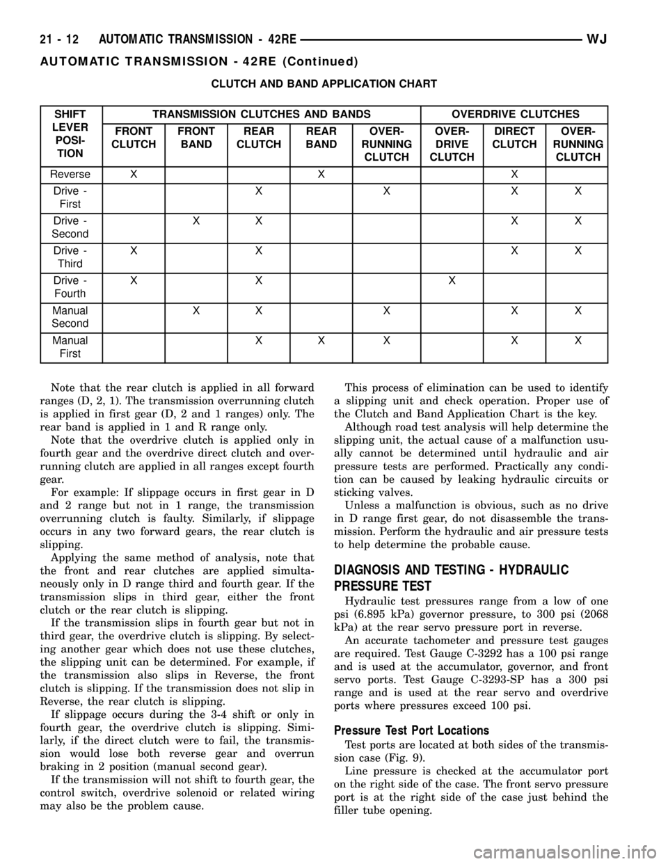
CLUTCH AND BAND APPLICATION CHART
SHIFT
LEVER
POSI-
TIONTRANSMISSION CLUTCHES AND BANDS OVERDRIVE CLUTCHES
FRONT
CLUTCHFRONT
BANDREAR
CLUTCHREAR
BANDOVER-
RUNNING
CLUTCHOVER-
DRIVE
CLUTCHDIRECT
CLUTCHOVER-
RUNNING
CLUTCH
Reverse X X X
Drive -
FirstXXXX
Drive -
SecondXX X X
Drive -
ThirdXX XX
Drive -
FourthXX X
Manual
SecondXXXXX
Manual
FirstXX X X X
Note that the rear clutch is applied in all forward
ranges (D, 2, 1). The transmission overrunning clutch
is applied in first gear (D, 2 and 1 ranges) only. The
rear band is applied in 1 and R range only.
Note that the overdrive clutch is applied only in
fourth gear and the overdrive direct clutch and over-
running clutch are applied in all ranges except fourth
gear.
For example: If slippage occurs in first gear in D
and 2 range but not in 1 range, the transmission
overrunning clutch is faulty. Similarly, if slippage
occurs in any two forward gears, the rear clutch is
slipping.
Applying the same method of analysis, note that
the front and rear clutches are applied simulta-
neously only in D range third and fourth gear. If the
transmission slips in third gear, either the front
clutch or the rear clutch is slipping.
If the transmission slips in fourth gear but not in
third gear, the overdrive clutch is slipping. By select-
ing another gear which does not use these clutches,
the slipping unit can be determined. For example, if
the transmission also slips in Reverse, the front
clutch is slipping. If the transmission does not slip in
Reverse, the rear clutch is slipping.
If slippage occurs during the 3-4 shift or only in
fourth gear, the overdrive clutch is slipping. Simi-
larly, if the direct clutch were to fail, the transmis-
sion would lose both reverse gear and overrun
braking in 2 position (manual second gear).
If the transmission will not shift to fourth gear, the
control switch, overdrive solenoid or related wiring
may also be the problem cause.This process of elimination can be used to identify
a slipping unit and check operation. Proper use of
the Clutch and Band Application Chart is the key.
Although road test analysis will help determine the
slipping unit, the actual cause of a malfunction usu-
ally cannot be determined until hydraulic and air
pressure tests are performed. Practically any condi-
tion can be caused by leaking hydraulic circuits or
sticking valves.
Unless a malfunction is obvious, such as no drive
in D range first gear, do not disassemble the trans-
mission. Perform the hydraulic and air pressure tests
to help determine the probable cause.
DIAGNOSIS AND TESTING - HYDRAULIC
PRESSURE TEST
Hydraulic test pressures range from a low of one
psi (6.895 kPa) governor pressure, to 300 psi (2068
kPa) at the rear servo pressure port in reverse.
An accurate tachometer and pressure test gauges
are required. Test Gauge C-3292 has a 100 psi range
and is used at the accumulator, governor, and front
servo ports. Test Gauge C-3293-SP has a 300 psi
range and is used at the rear servo and overdrive
ports where pressures exceed 100 psi.
Pressure Test Port Locations
Test ports are located at both sides of the transmis-
sion case (Fig. 9).
Line pressure is checked at the accumulator port
on the right side of the case. The front servo pressure
port is at the right side of the case just behind the
filler tube opening.
21 - 12 AUTOMATIC TRANSMISSION - 42REWJ
AUTOMATIC TRANSMISSION - 42RE (Continued)
Page 1581 of 2199

ADJUSTMENTS
ADJUSTMENT - BANDS
FRONT BAND
The front (kickdown) band adjusting screw is
located on the left side of the transmission case
above the manual valve and throttle valve levers.
(1) Raise vehicle.
(2) Loosen band adjusting screw locknut (Fig. 69).
Then back locknut off 3-5 turns. Be sure adjusting
screw turns freely in case. Apply lubricant to screw
threads if necessary.
(3) Tighten band adjusting screw to 8 N´m (72 in.
lbs.) torque with Inch Pound Torque Wrench
C-3380-A, a 3-in. extension and appropriate TorxŸ
socket.
CAUTION: If Adapter C-3705 is needed to reach the
adjusting screw, tighten the screw to only 5 N´m
(47-50 in. lbs.) torque.
(4) Back off front band adjusting screw 3 turns.
(5) Hold adjuster screw in position and tighten
locknut to 41 N´m (30 ft. lbs.) torque.
(6) Lower vehicle.
REAR BAND
The transmission oil pan must be removed for
access to the rear band adjusting screw.
(1) Raise vehicle.
(2) Remove transmission oil pan and drain fluid.(3) Loosen band adjusting screw locknut 5-6 turns
(Fig. 70). Be sure adjusting screw turns freely in
lever.
(4) Tighten adjusting screw to 8 N´m (72 in. lbs.)
torque.
(5) Back off adjusting screw 4 turns.
(6) Hold adjusting screw in place and tighten lock-
nut to 34 N´m (25 ft. lbs.) torque.
(7) Position new gasket on oil pan and install pan
on transmission. Tighten pan bolts to 17 N´m (13 ft.
lbs.) torque.
(8) Lower vehicle and refill transmission with
MopartATF +4, type 9602, fluid.
Fig. 68 Rear Band
1 - ADJUSTING SCREW
2 - LOCKNUT
3 - LEVER
4 - REAR BAND
5 - REACTION PIN
6 - O-RINGS
7 - PIVOT PINFig. 69 Front Band Adjustment Screw Location
1 - LOCK-NUT
2 - FRONT BAND ADJUSTER
Fig. 70 Rear Band Adjusting Screw Location
1 - ADJUSTING SCREW
2 - REAR BAND LEVER
3 - LOCKNUT
21 - 62 AUTOMATIC TRANSMISSION - 42REWJ
BANDS (Continued)
Page 1654 of 2199

VALVE BODY
DESCRIPTION
The valve body consists of a cast aluminum valve
body, a separator plate, and transfer plate. The valve
body contains valves and check balls that control
fluid delivery to the torque converter clutch, bands,
and frictional clutches. The valve body contains the
following components (Fig. 255), (Fig. 256), (Fig.
257), and (Fig. 258):
²Regulator valve
²Regulator valve throttle pressure plug
²Line pressure plug and sleeve
²Kickdown valve
²Kickdown limit valve
²1-2 shift valve
²1-2 control valve
²2-3 shift valve²2-3 governor plug
²3-4 shift valve
²3-4 timing valve
²3-4 quick fill valve
²3-4 accumulator
²Throttle valve
²Throttle pressure plug
²Switch valve
²Manual valve
²Converter clutch lock-up valve
²Converter clutch lock-up timing Valve
²Shuttle valve
²Shuttle valve throttle plug
²Boost Valve
²10 check balls
By adjusting the spring pressure acting on the reg-
ulator valve, transmission line pressure can be
adjusted.
Fig. 255 Upper Housing Control Valve Locations
1 - UPPER HOUSING 8 - MANUAL VALVE
2 - REGULATOR VALVE 9 - 1-2 GOVERNOR PLUG
3 - SWITCH VALVE 10 - GOVERNOR PLUG COVER
4 - REGULATOR VALVE SPRING 11 - THROTTLE PLUG
5 - KICKDOWN VALVE 12 - 2-3 GOVERNOR PLUG
6 - KICKDOWN DETENT 13 - SHUTTLE VALVE PRIMARY SPRING
7 - THROTTLE VALVE AND SPRING
WJAUTOMATIC TRANSMISSION - 42RE 21 - 135
Page 1686 of 2199

²pressure adjusting screw and bracket assembly
²throttle lever
²manual lever and shaft seal
²throttle lever shaft seal, washer, and E-clip
²fluid filter and screws
²detent ball and spring
²valve body screws
²governor pressure solenoid
²governor pressure sensor and retaining clip
²park lock rod and E-clip
ASSEMBLY
CAUTION: Do not force valves or plugs into place
during reassembly. If the valve body bores, valves
and plugs are free of distortion or burrs, the valve
body components should all slide into place easily.
In addition, do not overtighten the transfer plate
and valve body screws during reassembly. Over-
tightening can distort the housings resulting in
valve sticking, cross leakage and unsatisfactory
operation. Tighten valve body screws to recom-
mended torque only.
LOWER HOUSING
(1) Lubricate valves, springs, and the housing
valve and plug bores with clean transmission fluid
(Fig. 309).
(2) Install 3-4 timing valve spring and valve in
lower housing.
(3) Install 3-4 quick fill valve in lower housing.
(4) Install 3-4 quick fill valve spring and plug in
housing.
(5) Install timing valve end plate. Tighten end
plate screws to 4 N´m (35 in. lbs.) torque.
3-4 ACCUMULATOR
(1) Lubricate accumulator piston, seals and hous-
ing piston bore with clean transmission fluid (Fig.
310).
(2) Install new seal rings on accumulator piston.
(3) Install piston and spring in housing.
(4) Install end plate on housing.
TRANSFER PLATE
(1) Install rear clutch and rear servo check balls in
transfer plate (Fig. 311).
(2) Install filter screen in upper housing separator
plate (Fig. 312).
(3) Align and position upper housing separator
plate on transfer plate (Fig. 313).
(4) Install brace plate (Fig. 313). Tighten brace
attaching screws to 4 N´m (35 in. lbs.) torque.
(5) Install remaining separator plate attaching
screws. Tighten screws to 4 N´m (35 in. lbs.) torque.
UPPER AND LOWER HOUSING
(1) Position upper housing so internal passages
and check ball seats are facing upward. Then install
check balls in housing (Fig. 314). Eight check balls
are used. The single large check ball is approxi-
mately 8.7 mm (11/32 in.) diameter. The single small
check ball is approximately 4.8 mm (3/16 in.) in
diameter. The remaining 6 check balls are approxi-
mately 6.3 mm (1/4 in.) in diameter.
(2) Position assembled transfer plate and upper
housing separator plate on upper housing (Fig. 315).
Be sure filter screen is seated in proper housing
recess.
Fig. 311 Rear Clutch And Rear Servo Check Ball
Locations
1 - REAR CLUTCH CHECK BALL
2 - REAR SERVO CHECK BALL
3 - TRANSFER PLATE
Fig. 312 Separator Plate Filter Screen Installation
1 - UPPER HOUSING SEPARATOR PLATE
2 - FILTER SCREEN
WJAUTOMATIC TRANSMISSION - 42RE 21 - 167
VALVE BODY (Continued)
Page 1800 of 2199

OPERATION
The input gear is splined to the transmission out-
put shaft. It drives the mainshaft through the plan-
etary gear and range hub. The front output shaft is
operated by a drive chain that connects the shaft to a
drive sprocket on the mainshaft. The drive sprocket
is engaged/disengaged by the mode fork, which oper-
ates the mode sleeve and hub. The sleeve and hub
are not equipped with a synchro mechanism for shift-
ing.
OPERATING RANGES
NV242 operating ranges are 2WD (2-wheel drive),
4x4 part-time, 4x4 full time, and 4 Lo.
The 2WD and 4x4 full time ranges can be used at
any time and on any road surface.
The 4x4 part-time and 4 Lo ranges are for off road
use only. The only time these ranges can be used on
hard surface roads, is when the surface is covered
with snow and ice.
DIAGNOSIS AND TESTING - TRANSFER CASE - NV242
DIAGNOSIS CHART
CONDITION POSSIBLE CAUSE CORRECTION
Transfer case difficult to shift or will
not shift into desired range.1) Transfer case shift linkage
binding.1) Repair or replace linkage as
necessary.
2) Insufficient or incorrect lubricant. 2) Drain and refill transfer case with
the correct type and quantity of
lubricant.
3) Internal transfer case
components binding, worn, or
damaged.3) Repair or replace components as
necessary.
Transfer case noisy in all drive
modes.1) Insufficient or incorrect lubricant. 1) Drain and refill transfer case with
the correct type and quantity of
lubricant.
Lubricant leaking from transfer case
seals or vent.1) Transfer case overfilled. 1) Drain lubricant to the correct
level.
2) Transfer case vent closed or
restricted.2) Clean or replace vent as
necessary.
3) Transfer case seals damaged or
installed incorrectly.3) Replace suspect seal.
Transfer case will not shift through
4X4 part time range (light remains
on)1) Incomplete shift due to drivetrain
torque load.1) Momentarily release the
accelerator pedal to complete the
shift.
2) Incorrect tire pressure. 2) Correct tire pressure as
necessary.
3) Excessive Tire wear. 3) Correct tire condition as
necessary.
4) Excessive vehicle loading. 4) Correct as necessary.
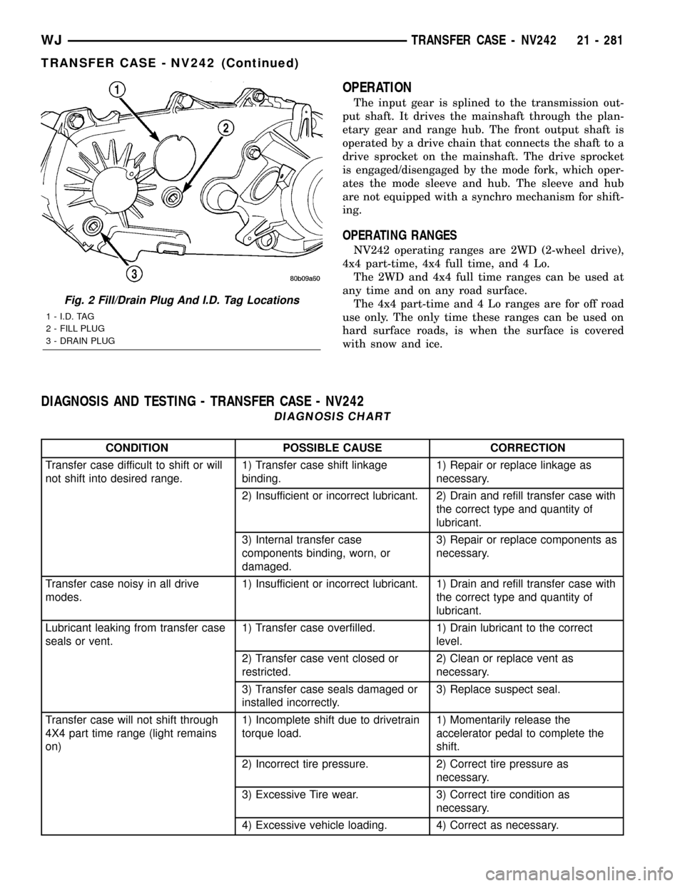
Fig. 2 Fill/Drain Plug And I.D. Tag Locations
1 - I.D. TAG
2 - FILL PLUG
3 - DRAIN PLUG
WJTRANSFER CASE - NV242 21 - 281
TRANSFER CASE - NV242 (Continued)
Page 1829 of 2199

FLUID
STANDARD PROCEDURE - FLUID DRAIN/
REFILL
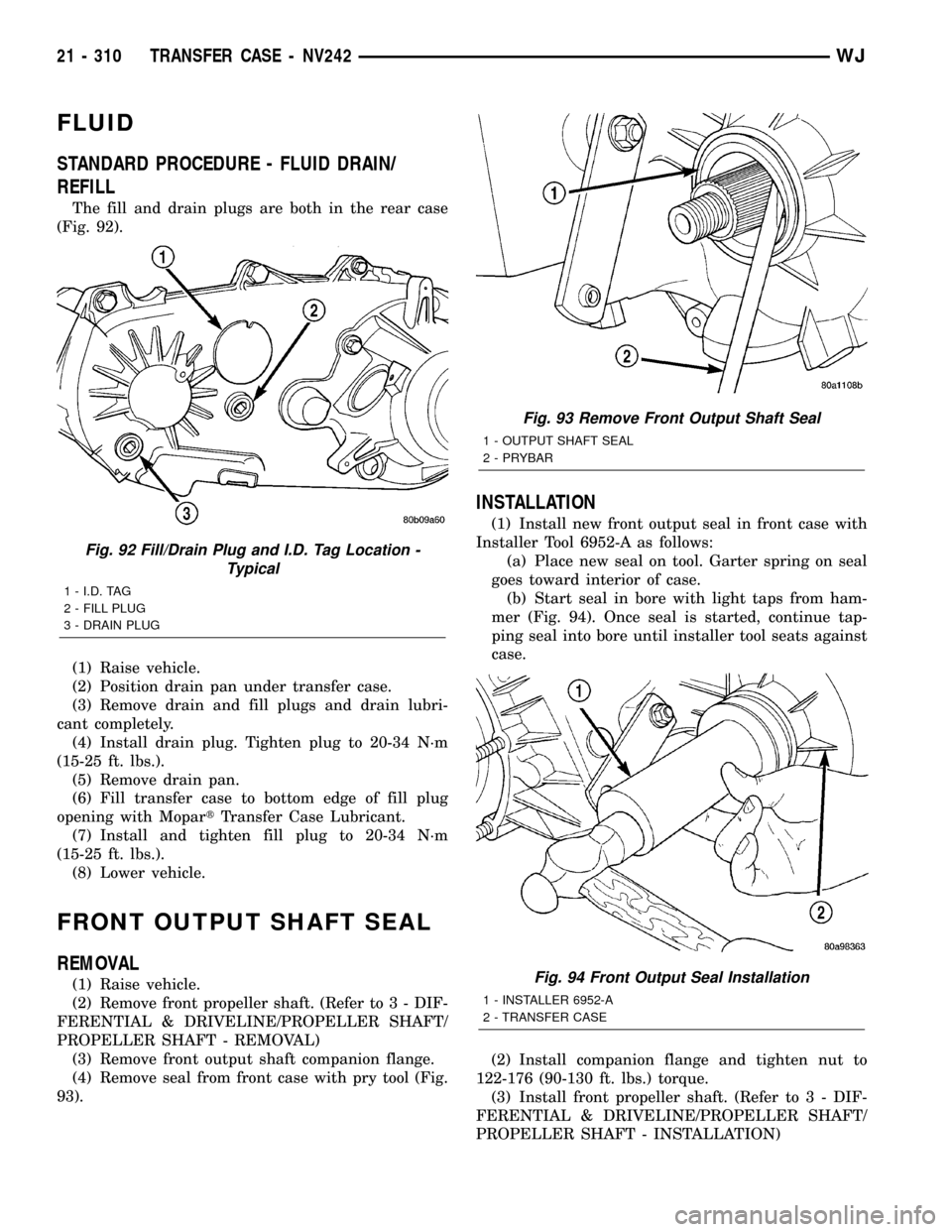
The fill and drain plugs are both in the rear case
(Fig. 92).
(1) Raise vehicle.
(2) Position drain pan under transfer case.
(3) Remove drain and fill plugs and drain lubri-
cant completely.
(4) Install drain plug. Tighten plug to 20-34 N´m
(15-25 ft. lbs.).
(5) Remove drain pan.
(6) Fill transfer case to bottom edge of fill plug
opening with MopartTransfer Case Lubricant.
(7) Install and tighten fill plug to 20-34 N´m
(15-25 ft. lbs.).
(8) Lower vehicle.
FRONT OUTPUT SHAFT SEAL
REMOVAL
(1) Raise vehicle.
(2) Remove front propeller shaft. (Refer to 3 - DIF-
FERENTIAL & DRIVELINE/PROPELLER SHAFT/
PROPELLER SHAFT - REMOVAL)
(3) Remove front output shaft companion flange.
(4) Remove seal from front case with pry tool (Fig.
93).
INSTALLATION
(1) Install new front output seal in front case with
Installer Tool 6952-A as follows:
(a) Place new seal on tool. Garter spring on seal
goes toward interior of case.
(b) Start seal in bore with light taps from ham-
mer (Fig. 94). Once seal is started, continue tap-
ping seal into bore until installer tool seats against
case.
(2) Install companion flange and tighten nut to
122-176 (90-130 ft. lbs.) torque.
(3) Install front propeller shaft. (Refer to 3 - DIF-
FERENTIAL & DRIVELINE/PROPELLER SHAFT/
PROPELLER SHAFT - INSTALLATION)
Fig. 92 Fill/Drain Plug and I.D. Tag Location -
Typical
1 - I.D. TAG
2 - FILL PLUG
3 - DRAIN PLUG
Fig. 93 Remove Front Output Shaft Seal
1 - OUTPUT SHAFT SEAL
2 - PRYBAR
Fig. 94 Front Output Seal Installation
1 - INSTALLER 6952-A
2 - TRANSFER CASE
21 - 310 TRANSFER CASE - NV242WJ
Page 1834 of 2199

TRANSFER CASE - NV247
TABLE OF CONTENTS
page page
TRANSFER CASE - NV247
DESCRIPTION........................315
OPERATION..........................316
DIAGNOSIS AND TESTING - TRANSFER
CASE - NV247.......................316
REMOVAL............................317
DISASSEMBLY........................317
CLEANING...........................324
INSPECTION.........................324
ASSEMBLY...........................326
INSTALLATION........................335
SPECIFICATIONS
TRANSFER CASE - NV247.............336
SPECIAL TOOLS
TRANSFER CASE - NV247.............337FLUID
STANDARD PROCEDURE - FLUID DRAIN/
REFILL............................338
FRONT OUTPUT SHAFT SEAL
REMOVAL............................338
INSTALLATION........................338
REAR RETAINER BUSHING AND SEAL
REMOVAL............................339
INSTALLATION........................339
SHIFT CABLE
REMOVAL............................340
INSTALLATION........................340
TRANSFER CASE - NV247
DESCRIPTION
The NV247 (Fig. 1) is an on-demand 4-wheel drive
transfer case with two operating ranges and a neu-
tral position. Operating ranges are 4-high and 4-low.
The 4-low range is used for extra pulling power in
off-road situations.
TRANSFER CASE IDENTIFICATION
A circular I.D. tag is attached to the rear case of
each NV247 transfer case (Fig. 2). The tag indicates
the following information:
²Model number
²Serial number
²Assembly number
²Gear ratio
²Location of manufacture
The transfer case serial number also represents
the date of build.
Fig. 1 NV247 Transfer Case
Fig. 2 Transfer Case I.D. Tag
1 - FILL PLUG
2 - I.D. TAG
3 - DRAIN PLUG
WJTRANSFER CASE - NV247 21 - 315
Page 1857 of 2199

FLUID
STANDARD PROCEDURE - FLUID DRAIN/
REFILL
The fill and drain plugs are both in the rear case
(Fig. 72).
(1) Raise vehicle.
(2) Position drain pan under transfer case.
(3) Remove drain and fill plugs and drain lubri-
cant completely.
(4) Install drain plug. Tighten plug to 20-34 N´m
(15-25 ft. lbs.).
(5) Remove drain pan.(6) Fill transfer case to bottom edge of fill plug
opening with MopartTransfer Case Lubricant.
(7) Install and tighten fill plug to 20-34 N´m
(15-25 ft. lbs.).
(8) Lower vehicle.
FRONT OUTPUT SHAFT SEAL
REMOVAL
(1) Raise vehicle on hoist.
(2) Remove front propeller shaft. (Refer to 3 - DIF-
FERENTIAL & DRIVELINE/PROPELLER SHAFT/
PROPELLER SHAFT - REMOVAL)
(3) Remove front output shaft companion shaft.
(4) Remove seal from front case with pry tool (Fig.
73).
INSTALLATION
(1) Install new front output seal in front case with
Installer Tool 6952-A as follows:
(a) Place new seal on tool. Garter spring on seal
goes toward interior of case.
(b) Start seal in bore with light taps from ham-
mer (Fig. 74). Once seal is started, continue tap-
ping seal into bore until installer tool seats against
case.
(2) Install companion flange and torque nut to
122-176 N´m (90-130 ft. lbs.).
(3) Install front propeller shaft. (Refer to 3 - DIF-
FERENTIAL & DRIVELINE/PROPELLER SHAFT/
PROPELLER SHAFT - INSTALLATION)
Installer, Bearign - 8128
Installer, Seal - 7884
Fig. 72 Fill/Drain Plug and I.D. Tag Location -
Typical
1 - I.D. TAG
2 - FILL PLUG
3 - DRAIN PLUG
Fig. 73 Remove Front Output Shaft Seal
1 - OUTPUT SHAFT SEAL
2 - PRYBAR
21 - 338 TRANSFER CASE - NV247WJ
TRANSFER CASE - NV247 (Continued)