Fill location JEEP GRAND CHEROKEE 2003 WJ / 2.G User Guide
[x] Cancel search | Manufacturer: JEEP, Model Year: 2003, Model line: GRAND CHEROKEE, Model: JEEP GRAND CHEROKEE 2003 WJ / 2.GPages: 2199, PDF Size: 76.01 MB
Page 277 of 2199
INSPECTION
Visually inspect the pressure valve gasket on the
cap. Replace cap if the gasket is swollen, torn or
worn. Inspect the area around radiator filler neck for
white deposits that indicate a leaking cap.
WATER PUMP INLET TUBE
REMOVAL
WARNING: CONSTANT TENSION HOSE CLAMPS
ARE USED ON MOST COOLING SYSTEM HOSES.
WHEN REMOVING OR INSTALLING, USE ONLY
TOOLS DESIGNED FOR SERVICING THIS TYPE OF
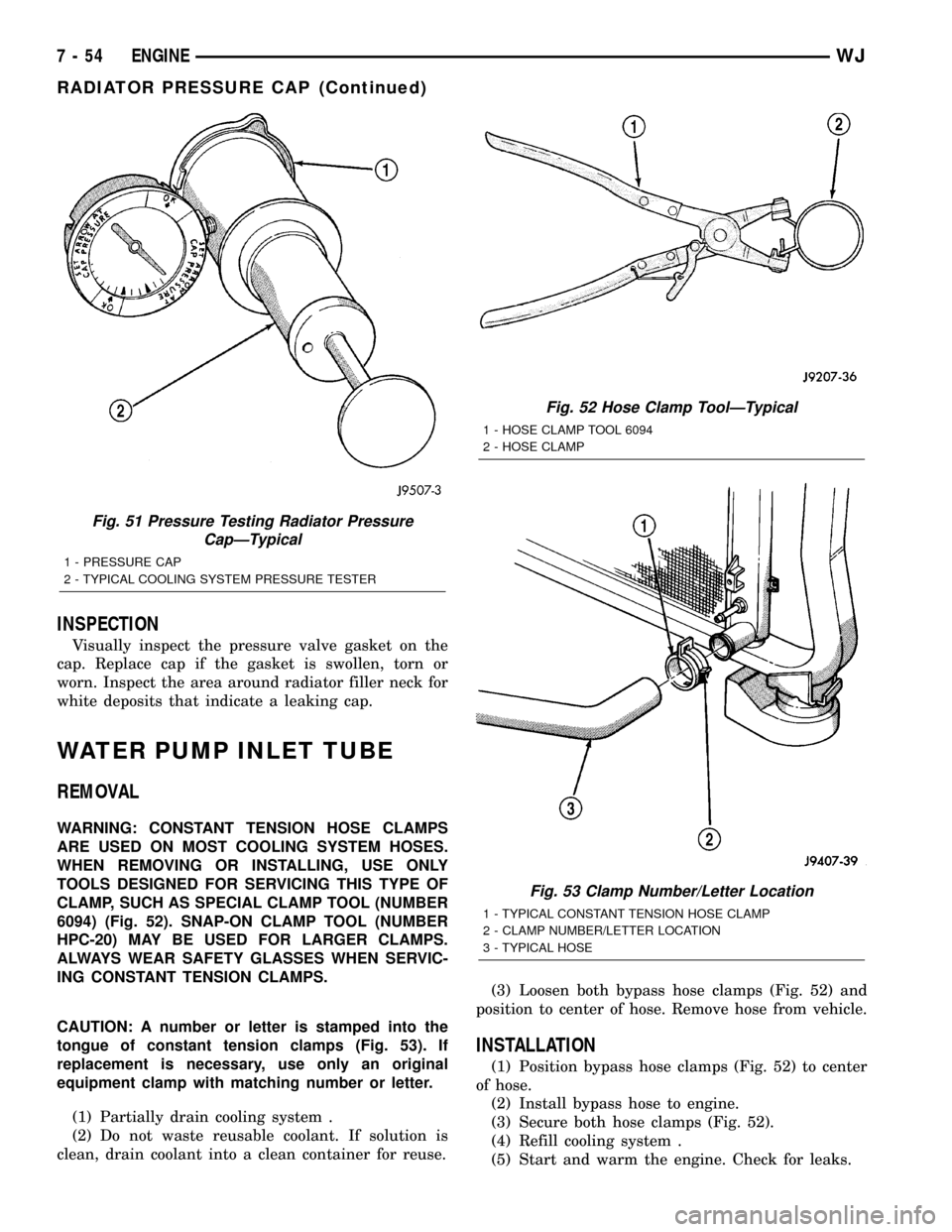
CLAMP, SUCH AS SPECIAL CLAMP TOOL (NUMBER
6094) (Fig. 52). SNAP-ON CLAMP TOOL (NUMBER
HPC-20) MAY BE USED FOR LARGER CLAMPS.
ALWAYS WEAR SAFETY GLASSES WHEN SERVIC-
ING CONSTANT TENSION CLAMPS.
CAUTION: A number or letter is stamped into the
tongue of constant tension clamps (Fig. 53). If
replacement is necessary, use only an original
equipment clamp with matching number or letter.
(1) Partially drain cooling system .
(2) Do not waste reusable coolant. If solution is
clean, drain coolant into a clean container for reuse.(3) Loosen both bypass hose clamps (Fig. 52) and
position to center of hose. Remove hose from vehicle.
INSTALLATION
(1) Position bypass hose clamps (Fig. 52) to center
of hose.
(2) Install bypass hose to engine.
(3) Secure both hose clamps (Fig. 52).
(4) Refill cooling system .
(5) Start and warm the engine. Check for leaks.
Fig. 51 Pressure Testing Radiator Pressure
CapÐTypical
1 - PRESSURE CAP
2 - TYPICAL COOLING SYSTEM PRESSURE TESTER
Fig. 52 Hose Clamp ToolÐTypical
1 - HOSE CLAMP TOOL 6094
2 - HOSE CLAMP
Fig. 53 Clamp Number/Letter Location
1 - TYPICAL CONSTANT TENSION HOSE CLAMP
2 - CLAMP NUMBER/LETTER LOCATION
3 - TYPICAL HOSE
7 - 54 ENGINEWJ
RADIATOR PRESSURE CAP (Continued)
Page 407 of 2199
OPERATION
Although cylinder firing order is the same as 4.0L
Jeep engines of previous years, spark plug firing is
not. The 3 coils dual-fire the spark plugs on cylinders
1-6, 2-5 and/or 3-4. When one cylinder is being fired
(on compression stroke), the spark to the opposite
cylinder is being wasted (on exhaust stroke).
Battery voltage is supplied to the three ignition
coils from the ASD relay. The Powertrain Control
Module (PCM) opens and closes the ignition coil
ground circuit for ignition coil operation.
Base ignition timing is not adjustable.By con-
trolling the coil ground circuit, the PCM is able to set
the base timing and adjust the ignition timing
advance. This is done to meet changing engine oper-
ating conditions.
The ignition coil is not oil filled. The windings are
embedded in an epoxy compound. This provides heat
and vibration resistance that allows the ignition coil
to be mounted on the engine.
Because of coil design, spark plug cables (second-
ary cables) are not used. The cables are integral
within the coil rail.
REMOVAL
A one-piece coil rail assembly containing three
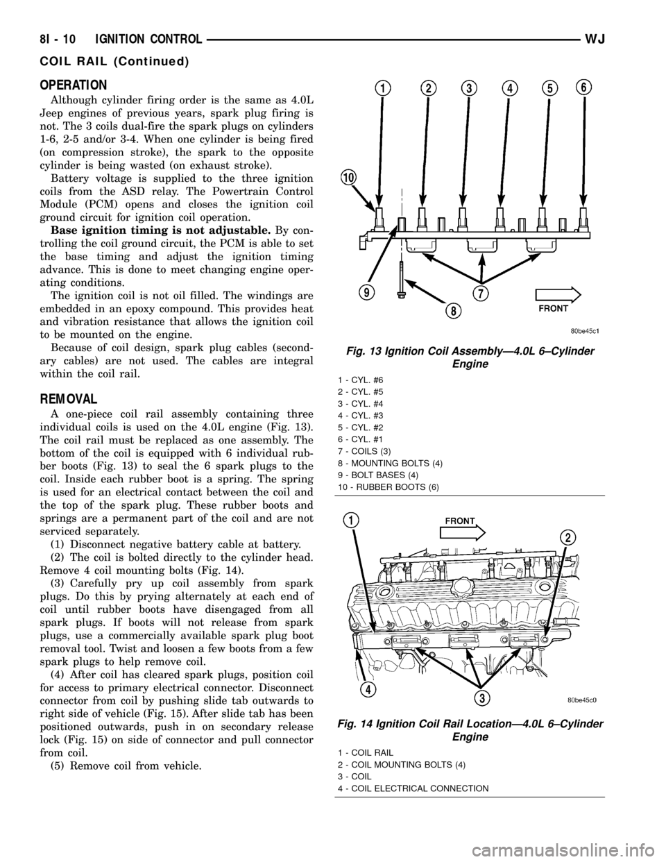
individual coils is used on the 4.0L engine (Fig. 13).
The coil rail must be replaced as one assembly. The
bottom of the coil is equipped with 6 individual rub-
ber boots (Fig. 13) to seal the 6 spark plugs to the
coil. Inside each rubber boot is a spring. The spring
is used for an electrical contact between the coil and
the top of the spark plug. These rubber boots and
springs are a permanent part of the coil and are not
serviced separately.
(1) Disconnect negative battery cable at battery.
(2) The coil is bolted directly to the cylinder head.
Remove 4 coil mounting bolts (Fig. 14).
(3) Carefully pry up coil assembly from spark
plugs. Do this by prying alternately at each end of
coil until rubber boots have disengaged from all
spark plugs. If boots will not release from spark
plugs, use a commercially available spark plug boot
removal tool. Twist and loosen a few boots from a few
spark plugs to help remove coil.
(4) After coil has cleared spark plugs, position coil
for access to primary electrical connector. Disconnect
connector from coil by pushing slide tab outwards to
right side of vehicle (Fig. 15). After slide tab has been
positioned outwards, push in on secondary release
lock (Fig. 15) on side of connector and pull connector
from coil.
(5) Remove coil from vehicle.
Fig. 13 Ignition Coil AssemblyÐ4.0L 6±Cylinder
Engine
1 - CYL. #6
2 - CYL. #5
3 - CYL. #4
4 - CYL. #3
5 - CYL. #2
6 - CYL. #1
7 - COILS (3)
8 - MOUNTING BOLTS (4)
9 - BOLT BASES (4)
10 - RUBBER BOOTS (6)
Fig. 14 Ignition Coil Rail LocationÐ4.0L 6±Cylinder
Engine
1 - COIL RAIL
2 - COIL MOUNTING BOLTS (4)
3 - COIL
4 - COIL ELECTRICAL CONNECTION
8I - 10 IGNITION CONTROLWJ
COIL RAIL (Continued)
Page 436 of 2199
FUEL GAUGE
DESCRIPTION
A fuel gauge is standard equipment on all instru-
ment clusters. The fuel gauge is located in the lower
left corner of the instrument cluster, to the left of the
tachometer. The fuel gauge consists of a movable
gauge needle or pointer controlled by the instrument
cluster circuitry and a fixed 90 degree scale on the
gauge dial face that reads left-to-right from E (or
Empty) to F (or Full). An International Control and
Display Symbol icon for ªFuelº is located on the
gauge dial face. An arrowhead pointed to the left side
of the vehicle is imprinted next to the ªFuelº icon on
the fuel gauge dial face to provide the driver with a
reminder as to the location of the fuel filler access.
The fuel gauge graphics are either white, gray and
orange against a black gauge dial face (base cluster)
or black and gray against a taupe gauge dial face
(premium cluster), making them clearly visible
within the instrument cluster in daylight. When illu-
minated from behind by the panel lamps dimmer
controlled cluster illumination lighting with the exte-
rior lamps turned On, the base cluster white gauge
graphics appear blue-green and the orange graphics
still appear orange, while the premium cluster taupe
gauge dial face appears blue-green with the black
graphics silhouetted against the illuminated back-
ground. The gray gauge graphics for both versions of
the cluster are not illuminated. The orange gauge
needle in the base cluster gauge is internally illumi-
nated, while the black gauge needle in the premium
cluster gauge is not.
Base cluster gauge illumination is provided by
replaceable incandescent bulb and bulb holder units
located on the instrument cluster electronic circuit
board. Premium cluster gauge illumination is pro-
vided by an integral electro-luminescent lamp that is
serviced as a unit with the instrument cluster. The
fuel gauge is serviced as a unit with the instrument
cluster.
OPERATION
The fuel gauge gives an indication to the vehicle
operator of the level of fuel in the fuel tank. This
gauge is controlled by the instrument cluster circuit
board based upon cluster programming and elec-
tronic messages received by the cluster from the
Powertrain Control Module (PCM) over the Program-
mable Communications Interface (PCI) data bus. The
fuel gauge is an air core magnetic unit that receives
battery current on the instrument cluster electronic
circuit board through the fused ignition switch out-
put (run-start) circuit whenever the ignition switch is
in the On or Start positions. The cluster is pro-
grammed to move the gauge needle back to the lowend of the scale after the ignition switch is turned to
the Off position. The instrument cluster circuitry
controls the gauge needle position and provides the
following features:
²Percent Tank Full Message- Each time the
cluster receives a message from the PCM indicating
the percent tank full, the cluster moves the gauge
needle to the relative fuel level position on the gauge
scale. The PCM applies an algorithm to the input
from the fuel tank sender to dampen gauge needle
movement against the negative effect that fuel slosh-
ing within the fuel tank can have on accurate inputs
to the PCM.
²Less Than 12.5 Percent Tank Full Message-
Each time the cluster receives messages from the
PCM indicating the percent tank full is less than
12.5 (one-eighth), the gauge needle is moved to the
proper position on the gauge scale and the low fuel
indicator is illuminated. The low fuel indicator
remains illuminated until the cluster receives mes-
sages from the PCM indicating that the percent tank
full is greater than 12.5 (one-eighth), or until the
ignition switch is turned to the Off position, which-
ever occurs first.
²Less Than Empty Percent Tank Full Mes-
sage- Each time the cluster receives a message from
the PCM indicating the percent tank full is less than
empty, the gauge needle is moved to the far left (low)
end of the gauge scale and the low fuel indicator is
illuminated immediately. This message would indi-
cate that the fuel tank sender input to the PCM is a
short circuit.
²More Than Full Percent Tank Full Message
- Each time the cluster receives a message from the
PCM indicating the percent tank full is more than
full, the gauge needle is moved to the far left (low)
end of the gauge scale and the low fuel indicator is
illuminated immediately. This message would indi-
cate that the fuel tank sender input to the PCM is an
open circuit.
²Communication Error- If the cluster fails to
receive a percent tank full message, it will hold the
gauge needle at the last indication for about twelve
seconds, until a new message is received, or until the
ignition switch is turned to the Off position, which-
ever occurs first. After twelve seconds, the cluster
will return the gauge needle to the low end of the
gauge scale.
²Actuator Test- Each time the cluster is put
through the actuator test, the gauge needle will be
swept across the entire gauge scale and back in order
to confirm the functionality of the gauge and the
cluster control circuitry.
The PCM continually monitors the fuel tank
sender to determine the fuel level. The PCM then
applies an algorithm to the input and sends the
WJINSTRUMENT CLUSTER 8J - 21
Page 610 of 2199
²Front Check Valve- The front washer system
check valve is integral to the wye fitting located in
the washer plumbing between the cowl plenum
washer hose and the front washer nozzles, and is
concealed beneath the cowl plenum cover/grille panel
at the base of the windshield.
²Front Washer Nozzle- Two fluidic front
washer nozzles are secured with integral snap fea-
tures to dedicated openings in the cowl plenum cover/
grille panel located near the base of the windshield.
²Front Washer Plumbing- The plumbing for
the front washer system consists of rubber hoses and
molded plastic fittings. The plumbing is routed along
the left side of the engine compartment from the
washer reservoir, and through the dash panel into
the cowl plenum to the front washer nozzle fittings
beneath the cowl plenum cover/grille panel.
²Front Washer Pump/Motor- The front washer
pump/motor unit is located in a dedicated hole on the
lower outboard side of the washer reservoir, behind
the inner fender liner ahead of the left front wheel.
The front washer pump is located ahead of and below
the rear washer pump.
²Front Wiper Arm- The two front wiper arms
are secured with nuts to the threaded studs on the
ends of the two wiper pivot shafts, which extend
through the cowl plenum cover/grille panel located
near the base of the windshield.
²Front Wiper Blade- The two front wiper
blades are secured to the two front wiper arms with
an integral latch, and are parked on the glass near
the bottom of the windshield when the front wiper
system is not in operation.
²Front Wiper Module- The front wiper pivot
shafts are the only visible components of the front
wiper module. The remainder of the module is con-
cealed within the cowl plenum beneath the cowl ple-
num cover/grille panel. The front wiper module
includes the module bracket, four rubber-isolated
wiper module mounts, the front wiper motor, the
wiper motor crank arm, the two wiper drive links,
and the two front wiper pivots.
²Rain Sensor Module- Models equipped with
the optional automatic wiper feature have a Rain
Sensor Module (RSM) located behind a trim cover on
a bracket bonded to the inside surface of the wind-
shield glass, just above the inside rear view mirror
mounting button.
²Right Multi-Function Switch- The right
(wiper) multi-function switch is secured to the right
side of the multi-function switch mounting housing
near the top of the steering column, just below the
steering wheel. Only the control stalk for the right
multi-function switch is visible, while the remainder
of the switch is concealed beneath the steering col-
umn shrouds. The right multi-function switch con-tains all of the switches and control circuitry for both
the front and rear wiper and washer systems.
²Washer Fluid Level Switch- The washer fluid
level switch is located in a dedicated hole near the
center of the forward surface of the washer reservoir,
behind the left front wheel house splash shield.
²Washer Reservoir- The washer reservoir is
concealed between the left inner fender shield and
the left outer fender panel, behind the inner fender
liner and ahead of the left front wheel. The washer
reservoir filler neck is the only visible portion of the
reservoir, and it is accessed from the left front corner
of the engine compartment.
²Wiper High-Low Relay- The wiper high-low
relay is an International Standards Organization
(ISO) micro relay located in the Power Distribution
Center (PDC) in the engine compartment near the
battery.
²Wiper On-Off Relay- The wiper on-off relay is
an International Standards Organization (ISO) micro
relay located in the Power Distribution Center (PDC)
in the engine compartment near the battery.
Hard wired circuitry connects the front wiper and
washer system components to the electrical system of
the vehicle. These hard wired circuits are integral to
several wire harnesses, which are routed throughout
the vehicle and retained by many different methods.
These circuits may be connected to each other, to the
vehicle electrical system and to the front wiper and
washer system components through the use of a com-
bination of soldered splices, splice block connectors,
and many different types of wire harness terminal
connectors and insulators. Refer to the appropriate
wiring information. The wiring information includes
wiring diagrams, proper wire and connector repair
procedures, further details on wire harness routing
and retention, as well as pin-out and location views
for the various wire harness connectors, splices and
grounds.
OPERATING MODES
The components of the front wiper and washer sys-
tem are designed to work in concert to provide the
following operating modes:
²Automatic Wiper- In models equipped with
the optional automatic wiper feature, the internal
circuitry of both the right (wiper) multi-function
switch, the rain sensor module, and the BCM work
in concert to provide an automatic wiper mode with
five sensitivity selections. The BCM tells the Rain
Sensor Module (RSM) when the automatic wiper
mode is selected and the manually selected sensitiv-
ity level, then the rain sensor module tells the BCM
each time enough water droplets have accumulated
within the wipe pattern on the windshield to require
front wiper operation. The BCM then automatically
WJFRONT WIPERS/WASHERS 8R - 3
FRONT WIPERS/WASHERS (Continued)
Page 634 of 2199
WASHER RESERVOIR
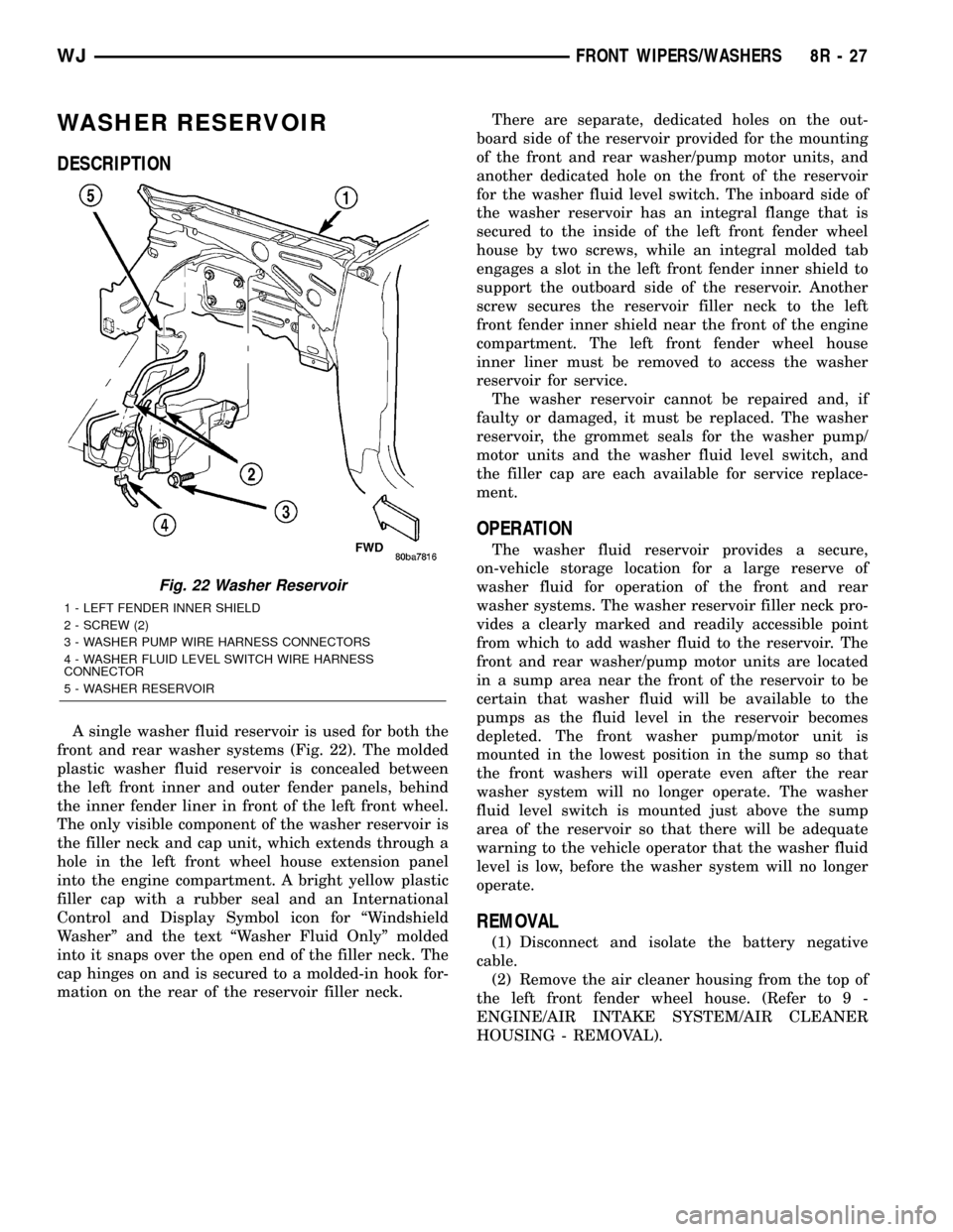
DESCRIPTION
A single washer fluid reservoir is used for both the
front and rear washer systems (Fig. 22). The molded
plastic washer fluid reservoir is concealed between
the left front inner and outer fender panels, behind
the inner fender liner in front of the left front wheel.
The only visible component of the washer reservoir is
the filler neck and cap unit, which extends through a
hole in the left front wheel house extension panel
into the engine compartment. A bright yellow plastic
filler cap with a rubber seal and an International
Control and Display Symbol icon for ªWindshield
Washerº and the text ªWasher Fluid Onlyº molded
into it snaps over the open end of the filler neck. The
cap hinges on and is secured to a molded-in hook for-
mation on the rear of the reservoir filler neck.There are separate, dedicated holes on the out-
board side of the reservoir provided for the mounting
of the front and rear washer/pump motor units, and
another dedicated hole on the front of the reservoir
for the washer fluid level switch. The inboard side of
the washer reservoir has an integral flange that is
secured to the inside of the left front fender wheel
house by two screws, while an integral molded tab
engages a slot in the left front fender inner shield to
support the outboard side of the reservoir. Another
screw secures the reservoir filler neck to the left
front fender inner shield near the front of the engine
compartment. The left front fender wheel house
inner liner must be removed to access the washer
reservoir for service.
The washer reservoir cannot be repaired and, if
faulty or damaged, it must be replaced. The washer
reservoir, the grommet seals for the washer pump/
motor units and the washer fluid level switch, and
the filler cap are each available for service replace-
ment.
OPERATION
The washer fluid reservoir provides a secure,
on-vehicle storage location for a large reserve of
washer fluid for operation of the front and rear
washer systems. The washer reservoir filler neck pro-
vides a clearly marked and readily accessible point
from which to add washer fluid to the reservoir. The
front and rear washer/pump motor units are located
in a sump area near the front of the reservoir to be
certain that washer fluid will be available to the
pumps as the fluid level in the reservoir becomes
depleted. The front washer pump/motor unit is
mounted in the lowest position in the sump so that
the front washers will operate even after the rear
washer system will no longer operate. The washer
fluid level switch is mounted just above the sump
area of the reservoir so that there will be adequate
warning to the vehicle operator that the washer fluid
level is low, before the washer system will no longer
operate.
REMOVAL
(1) Disconnect and isolate the battery negative
cable.
(2) Remove the air cleaner housing from the top of
the left front fender wheel house. (Refer to 9 -
ENGINE/AIR INTAKE SYSTEM/AIR CLEANER
HOUSING - REMOVAL).
Fig. 22 Washer Reservoir
1 - LEFT FENDER INNER SHIELD
2 - SCREW (2)
3 - WASHER PUMP WIRE HARNESS CONNECTORS
4 - WASHER FLUID LEVEL SWITCH WIRE HARNESS
CONNECTOR
5 - WASHER RESERVOIR
WJFRONT WIPERS/WASHERS 8R - 27
Page 641 of 2199

²Washer Reservoir- The rear washer system
shares a single reservoir with the front washer sys-
tem, but has its own dedicated washer pump/motor
and plumbing. The washer reservoir is concealed
between the left inner fender shield and the left
outer fender panel, behind the inner fender liner and
ahead of the left front wheel. The washer reservoir
filler neck is the only visible portion of the reservoir,
and it is accessed from the left front corner of the
engine compartment.
Features of the rear wiper and washer system
include the following:
²Continuous Wipe Mode- When the right
multi-function switch control sleeve is moved to the
On position, the rear wiper will be operated at a
fixed speed, continual wipe cycle until the switch
sleeve is moved to the Delay or Off positions, until
the ignition switch is turned to the Off position, or
until the liftgate flip-up glass is ajar.
²Intermittent Wipe Mode- When the right
multi-function switch control sleeve is moved to the
Delay position, the rear wiper will be operated in a
fixed interval, intermittent wipe cycle until the
switch sleeve is moved to the On or Off positions,
until the ignition switch is turned to the Off position,
until the liftgate flip-up glass is ajar, or until the
right multi-function switch control stalk is pushed
forward to activate the rear washer system. The
intermittent wipe mode delay time has a fixed delay
interval of about five to eight seconds between
sweeps.
²Washer Mode- When the right multi-function
switch control stalk is pushed forward to activate the
rear washer system, washer fluid will be dispensed
from the washer reservoir onto the liftgate glass
through the rear washer nozzle and the rear wiper
will operate in a fixed cycle (not intermittent) for as
long as the rear washer pump/motor unit remains
energized. When the control stalk is released from
the momentary Wash position, the wipe-after-wash
feature will continue to operate the rear wiper at a
fixed cycle for about three additional wiper sweeps
before returning to the previously selected mode.
Hard wired circuitry connects the rear wiper and
washer system components to the electrical system of
the vehicle. These hard wired circuits are integral to
several wire harnesses, which are routed throughout
the vehicle and retained by many different methods.
These circuits may be connected to each other, to the
vehicle electrical system and to the rear wiper and
washer system components through the use of a com-
bination of soldered splices, splice block connectors,
and many different types of wire harness terminal
connectors and insulators. Refer to the appropriate
wiring information. The wiring information includes
wiring diagrams, proper wire and connector repairprocedures, further details on wire harness routing
and retention, as well as pin-out and location views
for the various wire harness connectors, splices and
grounds.
OPERATION
The rear wiper and washer system is intended to
provide the vehicle operator with a convenient, safe,
and reliable means of maintaining visibility through
the liftgate glass. The various components of this sys-
tem are designed to convert electrical energy pro-
duced by the vehicle electrical system into the
mechanical action of the wiper blade to wipe the out-
side surface of the glass, as well as into the hydraulic
action of the washer system to apply washer fluid
stored in an on-board reservoir to the area of the
glass to be wiped. When combined, these components
provide the means to effectively maintain clear visi-
bility for the vehicle operator by removing excess
accumulations of rain, snow, bugs, mud, or other
minor debris from the outside liftgate glass surface
that might be encountered while driving the vehicle
under numerous types of inclement operating condi-
tions. The vehicle operator initiates all rear wiper
and washer system functions with the right multi-
function switch located on the right side of the steer-
ing column, just below the steering wheel. Moving
the switch control sleeve to a detent position selects
the rear wiper system operating mode. Moving the
switch control stalk forward to a momentary position
activates the rear washer pump/motor, which dis-
penses washer fluid onto the liftgate glass through
the rear washer nozzle and operates the rear wiper
system in the fixed cycle mode for as long as the
washer switch is closed plus about three wiper
sweeps.
When the ignition switch is in the Accessory or On
positions, battery current from a fuse in the Junction
Block (JB) is provided to the right multi-function
switch through a fused ignition switch output (run-
acc) circuit. A separate fuse in the JB provides bat-
tery current to the electronic control circuitry of the
rear wiper module through a fused B(+) circuit.
When the right multi-function switch control sleeve
On position is selected, the On position circuitry
within the switch directs a battery current rear
wiper motor control signal input to the rear wiper
module electronic circuitry, which causes the rear
wiper motor to run at a fixed continuous wipe cycle.
When the right multi-function switch control sleeve
Delay position is selected, the Delay position cir-
cuitry within the switch directs a battery current
rear washer switch output signal input to the rear
wiper module electronic circuitry, which causes the
rear wiper motor to run at a fixed intermittent wipe
cycle. When the right multi-function switch control
8R - 34 REAR WIPERS/WASHERSWJ
REAR WIPERS/WASHERS (Continued)
Page 1253 of 2199

FORM-IN-PLACE GASKET AND SEALER
APPLICATION
Assembling parts using a form-in-place gasket
requires care but it's easier then using precut gaskets.
MopartGasket Maker material should be applied
sparingly 1 mm (0.040 in.) diameter or less of sealant
to one gasket surface. Be certain the material sur-
rounds each mounting hole. Excess material can eas-
ily be wiped off. Components should be torqued in
place within 15 minutes. The use of a locating dowel
is recommended during assembly to prevent smear-
ing material off the location.
MopartEngine RTV GEN II or ATF RTV gasket
material should be applied in a continuous bead
approximately 3 mm (0.120 in.) in diameter. All
mounting holes must be circled. For corner sealing, a
3.17 or 6.35 mm (1/8 or 1/4 in.) drop is placed in the
center of the gasket contact area. Uncured sealant
may be removed with a shop towel. Components
should be torqued in place while the sealant is still
wet to the touch (within 10 minutes). The usage of a
locating dowel is recommended during assembly to
prevent smearing material off the location.
MopartGasket Sealant in an aerosol can should be
applied using a thin, even coat sprayed completely
over both surfaces to be joined, and both sides of a
gasket. Then proceed with assembly. Material in a
can w/applicator can be brushed on evenly over the
sealing surfaces. Material in an aerosol can should be
used on engines with multi-layer steel gaskets.
STANDARD PROCEDURE - REPAIR DAMAGED
OR WORN THREADS
CAUTION: Be sure that the tapped holes maintain
the original center line.
Damaged or worn threads can be repaired. Essen-
tially, this repair consists of:
²Drilling out worn or damaged threads.
²Tapping the hole with a special Heli-Coil Tap, or
equivalent.
²Installing an insert into the tapped hole to bring
the hole back to its original thread size.
STANDARD PROCEDUREÐHYDROSTATIC LOCK
CAUTION: DO NOT use the starter motor to rotate
the crankshaft. Severe damage could occur.
When an engine is suspected of hydrostatic lock
(regardless of what caused the problem), follow the
steps below.
(1) Perform the Fuel Pressure Release Procedure
(Refer to 14 - FUEL SYSTEM/FUEL DELIVERY -
STANDARD PROCEDURE).(2) Disconnect the negative cable(s) from the bat-
tery.
(3) Inspect air cleaner, induction system, and
intake manifold to ensure system is dry and clear of
foreign material.
(4) Place a shop towel around the spark plugs to
catch any fluid that may possibly be under pressure
in the cylinder head. Remove the spark plugs.
(5) With all spark plugs removed, rotate the crank-
shaft using a breaker bar and socket.
(6) Identify the fluid in the cylinders (coolant, fuel,
oil, etc.).
(7) Be sure all fluid has been removed from the
cylinders.
(8) Repair engine or components as necessary to
prevent this problem from occurring again.
(9) Squirt a small amount of engine oil into the
cylinders to lubricate the walls. This will prevent
damage on restart.
(10) Install new spark plugs. Tighten the spark
plugs to 41 N´m (30 ft. lbs.) torque.
(11) Drain engine oil. Remove and discard the oil
filter.
(12) Install the drain plug. Tighten the plug to 34
N´m (25 ft. lbs.) torque.
(13) Install a new oil filter.
(14) Fill engine crankcase with the specified
amount and grade of oil. (Refer to LUBRICATION &
MAINTENANCE - SPECIFICATIONS).
(15) Connect the negative cable(s) to the battery.
(16) Start the engine and check for any leaks.
STANDARD PROCEDURE - CYLINDER BORE
HONING
Before honing, stuff plenty of clean shop towels
under the bores and over the crankshaft to keep
abrasive materials from entering the crankshaft
area.
(1)
Used carefully, the Cylinder Bore Sizing Hone
C-823, equipped with 220 grit stones, is the best tool
for this job. In addition to deglazing, it will reduce
taper and out-of-round, as well as removing light scuff-
ing, scoring and scratches. Usually, a few strokes will
clean up a bore and maintain the required limits.
CAUTION: DO NOT use rigid type hones to remove
cylinder wall glaze.
(2) Deglazing of the cylinder walls may be done if
the cylinder bore is straight and round. Use a cylin-
der surfacing hone, Honing Tool C-3501, equipped
with 280 grit stones (C-3501-3810). about 20-60
strokes, depending on the bore condition, will be suf-
ficient to provide a satisfactory surface. Using honing
oil C-3501-3880, or a light honing oil, available from
major oil distributors.
9 - 10 ENGINE - 4.0LWJ
ENGINE - 4.0L (Continued)
Page 1254 of 2199
CAUTION: DO NOT use engine or transmission oil,
mineral spirits, or kerosene.
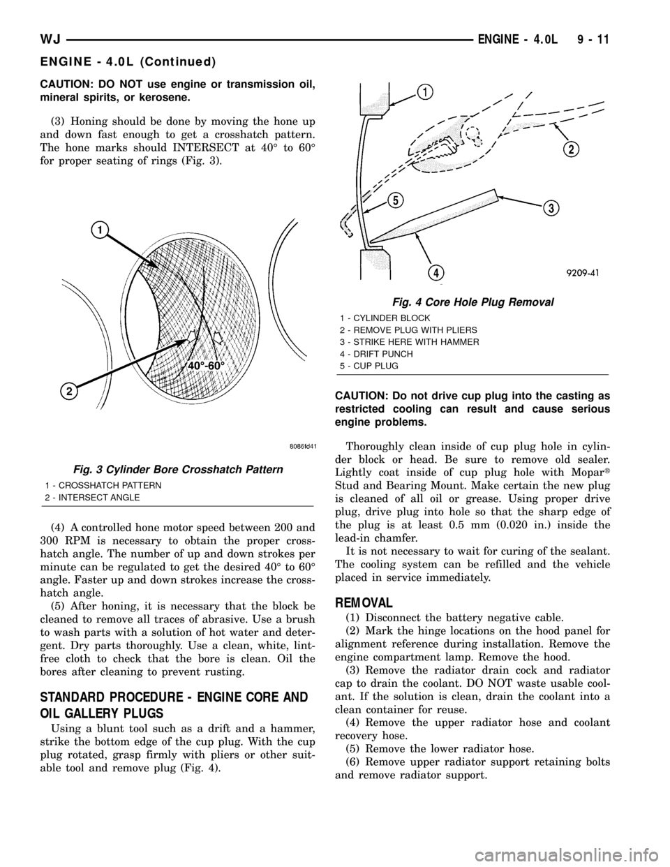
(3) Honing should be done by moving the hone up
and down fast enough to get a crosshatch pattern.
The hone marks should INTERSECT at 40É to 60É
for proper seating of rings (Fig. 3).
(4) A controlled hone motor speed between 200 and
300 RPM is necessary to obtain the proper cross-
hatch angle. The number of up and down strokes per
minute can be regulated to get the desired 40É to 60É
angle. Faster up and down strokes increase the cross-
hatch angle.
(5) After honing, it is necessary that the block be
cleaned to remove all traces of abrasive. Use a brush
to wash parts with a solution of hot water and deter-
gent. Dry parts thoroughly. Use a clean, white, lint-
free cloth to check that the bore is clean. Oil the
bores after cleaning to prevent rusting.
STANDARD PROCEDURE - ENGINE CORE AND
OIL GALLERY PLUGS
Using a blunt tool such as a drift and a hammer,
strike the bottom edge of the cup plug. With the cup
plug rotated, grasp firmly with pliers or other suit-
able tool and remove plug (Fig. 4).CAUTION: Do not drive cup plug into the casting as
restricted cooling can result and cause serious
engine problems.
Thoroughly clean inside of cup plug hole in cylin-
der block or head. Be sure to remove old sealer.
Lightly coat inside of cup plug hole with Mopart
Stud and Bearing Mount. Make certain the new plug
is cleaned of all oil or grease. Using proper drive
plug, drive plug into hole so that the sharp edge of
the plug is at least 0.5 mm (0.020 in.) inside the
lead-in chamfer.
It is not necessary to wait for curing of the sealant.
The cooling system can be refilled and the vehicle
placed in service immediately.
REMOVAL
(1) Disconnect the battery negative cable.
(2) Mark the hinge locations on the hood panel for
alignment reference during installation. Remove the
engine compartment lamp. Remove the hood.
(3) Remove the radiator drain cock and radiator
cap to drain the coolant. DO NOT waste usable cool-
ant. If the solution is clean, drain the coolant into a
clean container for reuse.
(4) Remove the upper radiator hose and coolant
recovery hose.
(5) Remove the lower radiator hose.
(6) Remove upper radiator support retaining bolts
and remove radiator support.
Fig. 3 Cylinder Bore Crosshatch Pattern
1 - CROSSHATCH PATTERN
2 - INTERSECT ANGLE
Fig. 4 Core Hole Plug Removal
1 - CYLINDER BLOCK
2 - REMOVE PLUG WITH PLIERS
3 - STRIKE HERE WITH HAMMER
4 - DRIFT PUNCH
5 - CUP PLUG
WJENGINE - 4.0L 9 - 11
ENGINE - 4.0L (Continued)
Page 1347 of 2199
CYLINDER HEAD COVER(S) -
RIGHT
DESCRIPTION
The cylinder head covers are made of die cast mag-
nesium, and are not interchangeable from side-to-
side. It is imperative that nothing rest on the
cylinder head covers. Prolonged contact with other
items may wear a hole in the cylinder head cover.
REMOVAL - RIGHT SIDE
(1) Disconnect battery negative cable.
(2) Remove air cleaner assembly, resonator assem-
bly and air inlet hose.
(3) Drain cooling system (Refer to 7 - COOLING -
STANDARD PROCEDURE).
(4) Remove accessory drive belt (Refer to 7 -
COOLING/ACCESSORY DRIVE/DRIVE BELTS -
REMOVAL).
(5) Remove air conditioning compressor retaining
bolts and move compressor to the left.
(6) Remove heater hoses.
(7) Disconnect injector and ignition coil connectors.
(8) Disconnect and remove positive crankcase ven-
tilation (PCV) hose.
(9) Remove oil fill tube.
(10) Un-clip injector and ignition coil harness and
move away from cylinder head cover.
(11) Remove right rear breather tube and filter
assembly.
(12) Remove cylinder head cover retaining bolts.
(13) Remove cylinder head cover.
NOTE: The gasket may be used again, provided no
cuts, tears, or deformation has occurred.
CLEANING
Clean cylinder head cover gasket surface.
Clean head rail, if necessary.
INSTALLATION - RIGHT SIDE
CAUTION: Do not use harsh cleaners to clean the
cylinder head covers. Severe damage to covers
may occur.
CAUTION: DO NOT allow other components includ-
ing the wire harness to rest on or against the
engine cylinder head cover. Prolonged contact with
other objects may wear a hole in the cylinder head
cover.
(1) Clean cylinder head cover and both sealing sur-
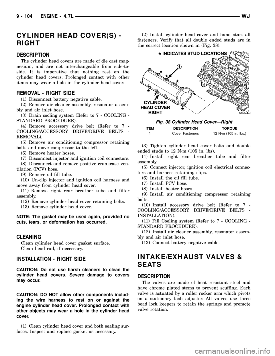
faces. Inspect and replace gasket as necessary.(2) Install cylinder head cover and hand start all
fasteners. Verify that all double ended studs are in
the correct location shown in (Fig. 38).
(3) Tighten cylinder head cover bolts and double
ended studs to 12 N´m (105 in. lbs).
(4) Install right rear breather tube and filter
assembly.
(5) Connect injector, ignition coil electrical connec-
tors and harness retaining clips.
(6) Install the oil fill tube.
(7) Install PCV hose.
(8) Install heater hoses.
(9) Install air conditioning compressor retaining
bolts.
(10) Install accessory drive belt (Refer to 7 -
COOLING/ACCESSORY DRIVE/DRIVE BELTS -
INSTALLATION).
(11) Fill Cooling system (Refer to 7 - COOLING -
STANDARD PROCEDURE).
(12) Install air cleaner assembly, resonator assem-
bly and air inlet hose.
(13) Connect battery negative cable.
INTAKE/EXHAUST VALVES &
SEATS
DESCRIPTION
The valves are made of heat resistant steel and
have chrome plated stems to prevent scuffing. Each
valve is actuated by a roller rocker arm which pivots
on a stationary lash adjuster. All valves use three
bead lock keepers to retain the springs and promote
valve rotation.
Fig. 38 Cylinder Head CoverÐRight
ITEM DESCRIPTION TORQUE
1 Cover Fasteners 12 N´m (105 in. lbs.)
9 - 104 ENGINE - 4.7LWJ
Page 1423 of 2199
STANDARD PROCEDURE - FUEL SYSTEM
PRESSURE RELEASE
Use following procedure if the fuel injector
rail is, or is not equipped with a fuel pressure
test port.
(1) Remove fuel fill cap.
(2) Remove fuel pump relay from Power Distribu-
tion Center (PDC). For location of relay, refer to label
on underside of PDC cover.
(3) Start and run engine until it stalls.
(4) Attempt restarting engine until it will no
longer run.
(5) Turn ignition key to OFF position.
CAUTION: Steps 1, 2, 3 and 4 must be performed to
relieve high pressure fuel from within fuel rail. Do
not attempt to use following steps to relieve this
pressure as excessive fuel will be forced into a cyl-
inder chamber.
(6) Unplug connector from any fuel injector.
(7) Attach one end of a jumper wire with alligator
clips (18 gauge or smaller) to either injector terminal.(8) Connect other end of jumper wire to positive
side of battery.
(9) Connect one end of a second jumper wire to
remaining injector terminal.
CAUTION: Powering an injector for more than a few
seconds will permanently damage the injector.
(10) Momentarily touch other end of jumper wire
to negative terminal of battery for no more than a
few seconds.
(11) Place a rag or towel below fuel line quick-con-
nect fitting at fuel rail.
(12) Disconnect quick-connect fitting at fuel rail.
Refer to Quick-Connect Fittings.
(13) Return fuel pump relay to PDC.
(14) One or more Diagnostic Trouble Codes (DTC's)
may have been stored in PCM memory due to fuel
pump relay removal. The DRBtscan tool must be
used to erase a DTC.
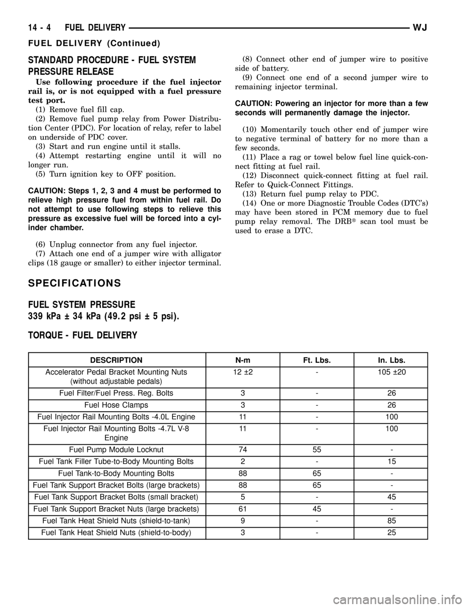
SPECIFICATIONS
FUEL SYSTEM PRESSURE
339 kPa 34 kPa (49.2 psi 5 psi).
TORQUE - FUEL DELIVERY
DESCRIPTION N-m Ft. Lbs. In. Lbs.
Accelerator Pedal Bracket Mounting Nuts
(without adjustable pedals)12 2 - 105 20
Fuel Filter/Fuel Press. Reg. Bolts 3 - 26
Fuel Hose Clamps 3 - 26
Fuel Injector Rail Mounting Bolts -4.0L Engine 11 - 100
Fuel Injector Rail Mounting Bolts -4.7L V-8
Engine11 - 100
Fuel Pump Module Locknut 74 55 -
Fuel Tank Filler Tube-to-Body Mounting Bolts 2 - 15
Fuel Tank-to-Body Mounting Bolts 88 65 -
Fuel Tank Support Bracket Bolts (large brackets) 88 65 -
Fuel Tank Support Bracket Bolts (small bracket) 5 - 45
Fuel Tank Support Bracket Nuts (large brackets) 61 45 -
Fuel Tank Heat Shield Nuts (shield-to-tank) 9 - 85
Fuel Tank Heat Shield Nuts (shield-to-body) 3 - 25
14 - 4 FUEL DELIVERYWJ
FUEL DELIVERY (Continued)