Front bumper JEEP GRAND CHEROKEE 2003 WJ / 2.G Owner's Manual
[x] Cancel search | Manufacturer: JEEP, Model Year: 2003, Model line: GRAND CHEROKEE, Model: JEEP GRAND CHEROKEE 2003 WJ / 2.GPages: 2199, PDF Size: 76.01 MB
Page 1518 of 2199
INSTALLATION - 3/8(PRESSURE HOSE
NOTE: Lubrication and a new o-ring must be used
when reinstalling.
(1) Install the hoses to the vehicle.
(2) Reconnect the high pressure hose to the
hydraulic fan motor (Fig. 10) Tighten the hose to
22.5 N´m (17 ft.lbs.).
(3) Reconnect the high pressure hose to the power
steering gear (Fig. 10) Tighten the hose to 22.5 N´m
(17 ft.lbs.).
(4) Install the hose to the clipped position on the
fan shroud.
(5) Install the metal skid plate.
(6) Install the air box,(Refer to 9 - ENGINE/AIR
INTAKE SYSTEM/AIR CLEANER HOUSING -
INSTALLATION).
(7) Refill the power steering fluid and bleed the
system,(Refer to 19 - STEERING/PUMP - STAN-
DARD PROCEDURE).
INSTALLATION - 3/8(RETURN HOSE
(1) Install the hoses to the vehicle.
(2) Reconnect the rubber hose to the steering
cooler outlet tube (Fig. 12) Tighten the hose clamp.
(3) Reconnect the rubber hose to the power steer-
ing reservoir (Fig. 12) Tighten the hose clamp.
(4) Install the air box,(Refer to 9 - ENGINE/AIR
INTAKE SYSTEM/AIR CLEANER HOUSING -
INSTALLATION).
(5) Refill the power steering fluid and bleed the
system,(Refer to 19 - STEERING/PUMP - STAN-
DARD PROCEDURE).
INSTALLATION - 3/8(GEAR OUTLET HOSE
NOTE: Lubrication and a new o-ring must be used
when reinstalling.
(1) Install the hoses to the vehicle.
(2) Reconnect the rubber hose to the steering
cooler inlet tube (Fig. 11) Tighten the hose clamp.
(3)
Reconnect the metal tube to the power steering
gear (Fig. 11) Tighten the hose to 22.5 N´m (17 ft.lbs.).
(4) Install the air box,(Refer to 9 - ENGINE/AIR
INTAKE SYSTEM/AIR CLEANER HOUSING -
INSTALLATION).
(5) Refill the power steering fluid and bleed the
system,(Refer to 19 - STEERING/PUMP - STAN-
DARD PROCEDURE).
INSTALLATION - INLET COOLER HOSE
(1) Install the cooler hose to the vehicle.
(2) Reconnect the cooler hose at the gear.
(3) Reconnect the lower hose at cooler (Fig. 6).
Tighten the hose to 22.5 N´m (17 ft.lbs.)
(4) Install the bracket holding the cooler hoses
(Fig. 13).(5) Install the air box,(Refer to 9 - ENGINE/AIR
INTAKE SYSTEM/AIR CLEANER HOUSING -
INSTALLATION).
(6) Install the grille opening reinforcement panel
(7) Install the front fascia grille assembly, (Refer to
13 - FRAMES & BUMPERS/BUMPERS/FRONT
FASCIA - INSTALLATION).
(8) Reconnect negative battery cable at battery.
(9) Refill the power steering fluid and bleed the
system,(Refer to 19 - STEERING/PUMP - STAN-
DARD PROCEDURE).
INSTALLATION - OUTLET COOLER HOSE
(1) Install the cooler hose to the vehicle.
(2) Reconnect the cooler hose at the reservoir.
(3) Reconnect the upper hose at the cooler (Fig. 6).
Tighten the hose to 22.5 N´m (17 ft. lbs.)
(4) Install the bracket holding the cooler hoses
(Fig. 13). Tighten the bracket to 22.5 N´m (17 ft. lbs.)
(5) Install the air box,(Refer to 9 - ENGINE/AIR
INTAKE SYSTEM/AIR CLEANER HOUSING -
INSTALLATION).
(6) Install the grille opening reinforcement panel
(7) Install the front fascia grille assembly, (Refer to
13 - FRAMES & BUMPERS/BUMPERS/FRONT
FASCIA - INSTALLATION).
(8) Reconnect negative battery cable at battery.
(9) Refill the power steering fluid and bleed the
system,(Refer to 19 - STEERING/PUMP - STAN-
DARD PROCEDURE).
PULLEY
DESCRIPTION
POWER STEERING PUMP PULLEY - 3.1L
DIESEL
To service the power steering pump pulley on the
3.1L turbo diesel engine. Refer to the power steering
pump removal and installation procedure in this
group. The pulley must be removed to service the
pump assembly. Detailed instructions are provided in
the pump procedure.
REMOVAL
CAUTION: On vehicles equipped with the 4.0L or
4.7L, Do not reuse the old power steering pump
pulley it is not intended for reuse. A new pulley
must be installed if removed.
(1) Remove pump assembly.
(2) Remove pulley from pump with Puller C-4333
or equivalent puller (Fig. 14).
WJPUMP 19 - 41
HOSES - 4.7L (Continued)
Page 1902 of 2199
(8) Loosen screw under hood hinge, attaching
fender to engine compartment rail.
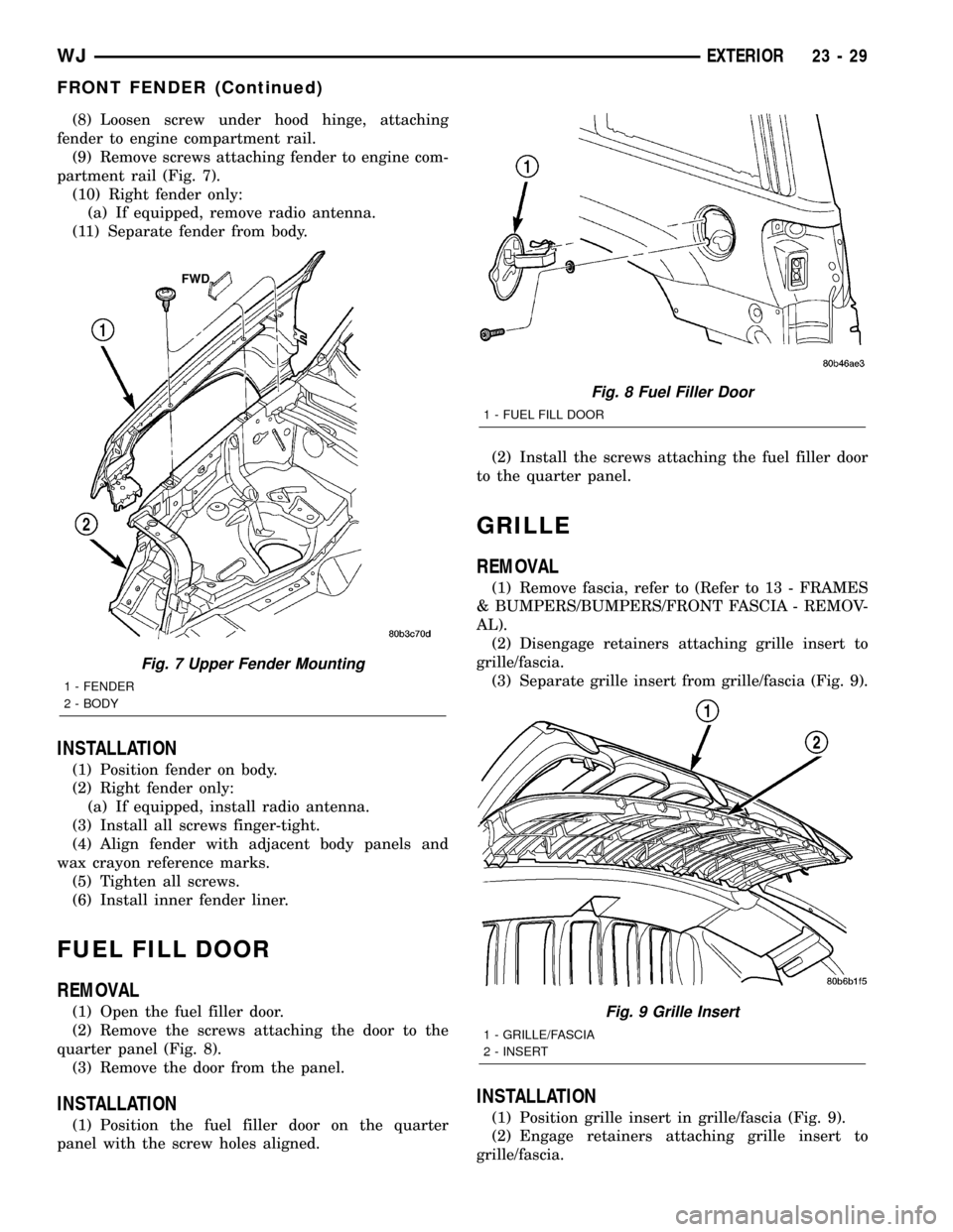
(9) Remove screws attaching fender to engine com-
partment rail (Fig. 7).
(10) Right fender only:
(a) If equipped, remove radio antenna.
(11) Separate fender from body.
INSTALLATION
(1) Position fender on body.
(2) Right fender only:
(a) If equipped, install radio antenna.
(3) Install all screws finger-tight.
(4) Align fender with adjacent body panels and
wax crayon reference marks.
(5) Tighten all screws.
(6) Install inner fender liner.
FUEL FILL DOOR
REMOVAL
(1) Open the fuel filler door.
(2) Remove the screws attaching the door to the
quarter panel (Fig. 8).
(3) Remove the door from the panel.
INSTALLATION
(1) Position the fuel filler door on the quarter
panel with the screw holes aligned.(2) Install the screws attaching the fuel filler door
to the quarter panel.
GRILLE
REMOVAL
(1) Remove fascia, refer to (Refer to 13 - FRAMES
& BUMPERS/BUMPERS/FRONT FASCIA - REMOV-
AL).
(2) Disengage retainers attaching grille insert to
grille/fascia.
(3) Separate grille insert from grille/fascia (Fig. 9).
INSTALLATION
(1) Position grille insert in grille/fascia (Fig. 9).
(2) Engage retainers attaching grille insert to
grille/fascia.
Fig. 7 Upper Fender Mounting
1 - FENDER
2 - BODY
Fig. 8 Fuel Filler Door
1 - FUEL FILL DOOR
Fig. 9 Grille Insert
1 - GRILLE/FASCIA
2 - INSERT
WJEXTERIOR 23 - 29
FRONT FENDER (Continued)
Page 1903 of 2199
(3) Install fascia, refer to (Refer to 13 - FRAMES
& BUMPERS/BUMPERS/FRONT FASCIA - INSTAL-
LATION).
HEADLAMP MOUNTING
MODULE
REMOVAL
CAUTION: Take special care when handling the
HMM not to damage the upper mounting tabs. Step
#3 must be performed prior to removing HMM from
the vehicle to prevent damage to HMM.
(1) Remove fascia, refer to (Refer to 13 - FRAMES
& BUMPERS/BUMPERS/FRONT FASCIA - REMOV-
AL).
(2) Remove inner fender liner.
(3) Reach into the wheelhouse opening and disen-
gage the retainer attaching the HMM to each side of
the body.
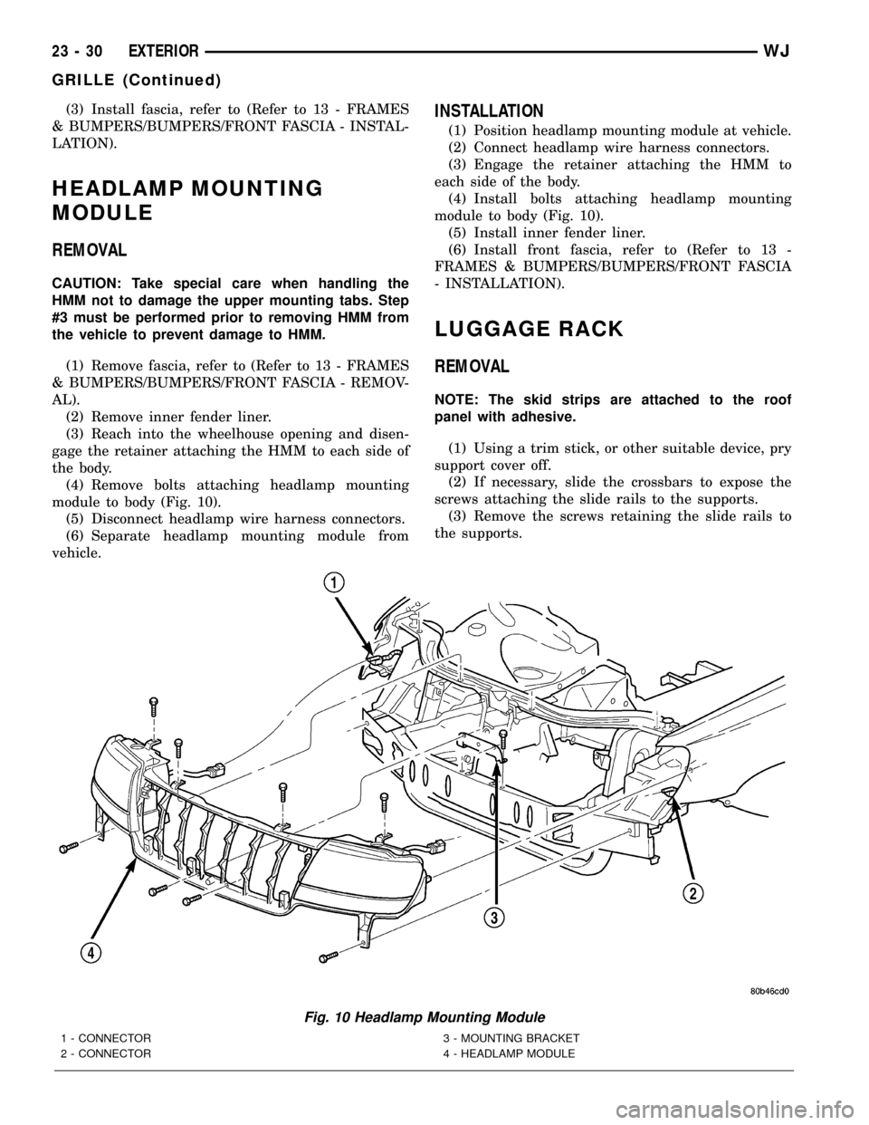
(4) Remove bolts attaching headlamp mounting
module to body (Fig. 10).
(5) Disconnect headlamp wire harness connectors.
(6) Separate headlamp mounting module from
vehicle.
INSTALLATION
(1) Position headlamp mounting module at vehicle.
(2) Connect headlamp wire harness connectors.
(3) Engage the retainer attaching the HMM to
each side of the body.
(4) Install bolts attaching headlamp mounting
module to body (Fig. 10).
(5) Install inner fender liner.
(6) Install front fascia, refer to (Refer to 13 -
FRAMES & BUMPERS/BUMPERS/FRONT FASCIA
- INSTALLATION).
LUGGAGE RACK
REMOVAL
NOTE: The skid strips are attached to the roof
panel with adhesive.
(1) Using a trim stick, or other suitable device, pry
support cover off.
(2) If necessary, slide the crossbars to expose the
screws attaching the slide rails to the supports.
(3) Remove the screws retaining the slide rails to
the supports.
Fig. 10 Headlamp Mounting Module
1 - CONNECTOR
2 - CONNECTOR3 - MOUNTING BRACKET
4 - HEADLAMP MODULE
23 - 30 EXTERIORWJ
GRILLE (Continued)
Page 1907 of 2199
(6) Remove bolts attaching hinges to hood.
(7) With the aid of a helper, remove hood from
vehicle.
INSTALLATION
(1) Position hood on hinges.
(2) Install bolts finger-tight.
(3) Align hinges with installation reference marks
and tighten bolts.
(4) Install hood support prop rods.
(5) Connect underhood lamp connector.
(6) Inspect hood for proper alignment and adjust
as necessary.
ADJUSTMENTS
HOOD ADJUSTMENT
The hood attaching holes are enlarged to aid front,
back and side to side adjustment.
(1) If hood is low in relation to cowl panel, insert
shims between hinge and hood.
(2) Adjust hood bumper in or out to adjust hood-
to-fender height alignment.
(3) Adjust the hood latch as necessary. Tighten the
nuts to 11N´m (8 ft. lbs.).
(4) Align the latch striker so that striker enters
the latch squarely and without binding.
INSULATION
REMOVAL
(1) Raise the hood.
(2) Remove the insulation panel fasteners.
(3) Remove the hood insulation panel.
INSTALLATION
(1) Position the insulation panel on the underside
of the hood.
(2) Install the insulation panel fasteners.
(3) Close the hood.
LATCH
REMOVAL
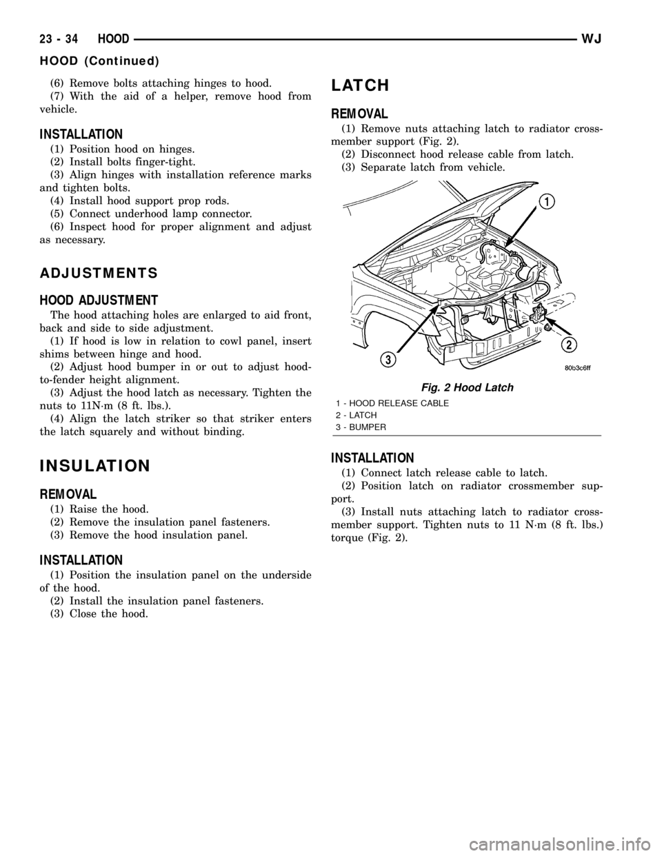
(1) Remove nuts attaching latch to radiator cross-
member support (Fig. 2).
(2) Disconnect hood release cable from latch.
(3) Separate latch from vehicle.
INSTALLATION
(1) Connect latch release cable to latch.
(2) Position latch on radiator crossmember sup-
port.
(3) Install nuts attaching latch to radiator cross-
member support. Tighten nuts to 11 N´m (8 ft. lbs.)
torque (Fig. 2).
Fig. 2 Hood Latch
1 - HOOD RELEASE CABLE
2-LATCH
3 - BUMPER
23 - 34 HOODWJ
HOOD (Continued)
Page 1919 of 2199
GLOVE BOX
STANDARD PROCEDURE - GLOVE BOX ROLL
DOWN
WARNING: ON VEHICLES EQUIPPED WITH AIR-
BAGS, DISABLE THE AIRBAG SYSTEM BEFORE
ATTEMPTING ANY STEERING WHEEL, STEERING
COLUMN, OR INSTRUMENT PANEL COMPONENT
DIAGNOSIS OR SERVICE. DISCONNECT AND ISO-
LATE THE BATTERY NEGATIVE (GROUND) CABLE,
THEN WAIT TWO MINUTES FOR THE AIRBAG SYS-
TEM CAPACITOR TO DISCHARGE BEFORE PER-
FORMING FURTHER DIAGNOSIS OR SERVICE. THIS
IS THE ONLY SURE WAY TO DISABLE THE AIRBAG
SYSTEM. FAILURE TO TAKE THE PROPER PRE-
CAUTIONS COULD RESULT IN ACCIDENTAL AIR-
BAG DEPLOYMENT AND POSSIBLE PERSONAL
INJURY.
(1) Disconnect and isolate the battery negative
cable.
(2) Open the glove box until the integral stops on
the back edge of the glove box bin are resting against
the rubber stop bumpers in the upper glove box open-
ing reinforcement.
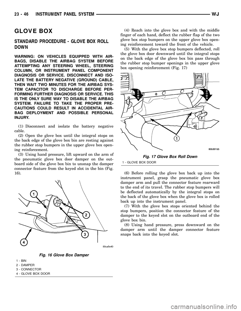
(3) Using hand pressure, lift upward on the arm of
the pneumatic glove box door damper on the out-
board side of the glove box bin to unsnap the damper
connector feature from the keyed slot in the bin (Fig.
16).(4) Reach into the glove box and with the middle
finger of each hand, deflect the rubber flap of the two
glove box stop bumpers on the upper glove box open-
ing reinforcement toward the front of the vehicle.
(5) With the glove box stop bumpers deflected, roll
the glove box door downward until the integral stops
on the back edge of the glove box bin pass through
the rubber stop bumper openings in the upper glove
box opening reinforcement (Fig. 17)
(6) Before rolling the glove box back up into the
instrument panel, grasp the pneumatic glove box
damper arm and pull the connector feature rearward
to the end of its travel. The rubber stop bumpers will
be deflected automatically by the integral stops on
the back of the glove box when the glove box is rolled
back up into the instrument panel.
(7) With the glove box stops oriented behind the
stop bumpers, position the connector feature of the
damper to the keyed slot on the outboard end of the
glove box bin.
(8) Using hand pressure, press downward on the
damper arm until the damper connector feature
snaps back into the keyed slot.
Fig. 16 Glove Box Damper
1 - BIN
2 - DAMPER
3 - CONNECTOR
4 - GLOVE BOX DOOR
Fig. 17 Glove Box Roll Down
1 - GLOVE BOX DOOR
23 - 46 INSTRUMENT PANEL SYSTEMWJ
Page 2195 of 2199
REMOVAL
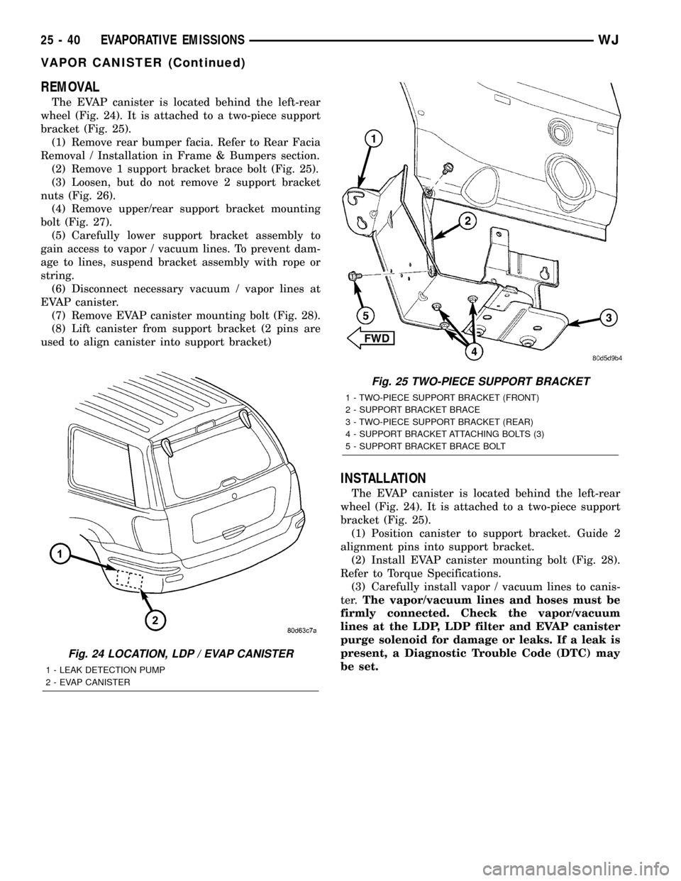
The EVAP canister is located behind the left-rear
wheel (Fig. 24). It is attached to a two-piece support
bracket (Fig. 25).
(1) Remove rear bumper facia. Refer to Rear Facia
Removal / Installation in Frame & Bumpers section.
(2) Remove 1 support bracket brace bolt (Fig. 25).
(3) Loosen, but do not remove 2 support bracket
nuts (Fig. 26).
(4) Remove upper/rear support bracket mounting
bolt (Fig. 27).
(5) Carefully lower support bracket assembly to
gain access to vapor / vacuum lines. To prevent dam-
age to lines, suspend bracket assembly with rope or
string.
(6) Disconnect necessary vacuum / vapor lines at
EVAP canister.
(7) Remove EVAP canister mounting bolt (Fig. 28).
(8) Lift canister from support bracket (2 pins are
used to align canister into support bracket)
INSTALLATION
The EVAP canister is located behind the left-rear
wheel (Fig. 24). It is attached to a two-piece support
bracket (Fig. 25).
(1) Position canister to support bracket. Guide 2
alignment pins into support bracket.
(2) Install EVAP canister mounting bolt (Fig. 28).
Refer to Torque Specifications.
(3) Carefully install vapor / vacuum lines to canis-
ter.The vapor/vacuum lines and hoses must be
firmly connected. Check the vapor/vacuum
lines at the LDP, LDP filter and EVAP canister
purge solenoid for damage or leaks. If a leak is
present, a Diagnostic Trouble Code (DTC) may
be set.
Fig. 24 LOCATION, LDP / EVAP CANISTER
1 - LEAK DETECTION PUMP
2 - EVAP CANISTER
Fig. 25 TWO-PIECE SUPPORT BRACKET
1 - TWO-PIECE SUPPORT BRACKET (FRONT)
2 - SUPPORT BRACKET BRACE
3 - TWO-PIECE SUPPORT BRACKET (REAR)
4 - SUPPORT BRACKET ATTACHING BOLTS (3)
5 - SUPPORT BRACKET BRACE BOLT
25 - 40 EVAPORATIVE EMISSIONSWJ
VAPOR CANISTER (Continued)
Page 2196 of 2199
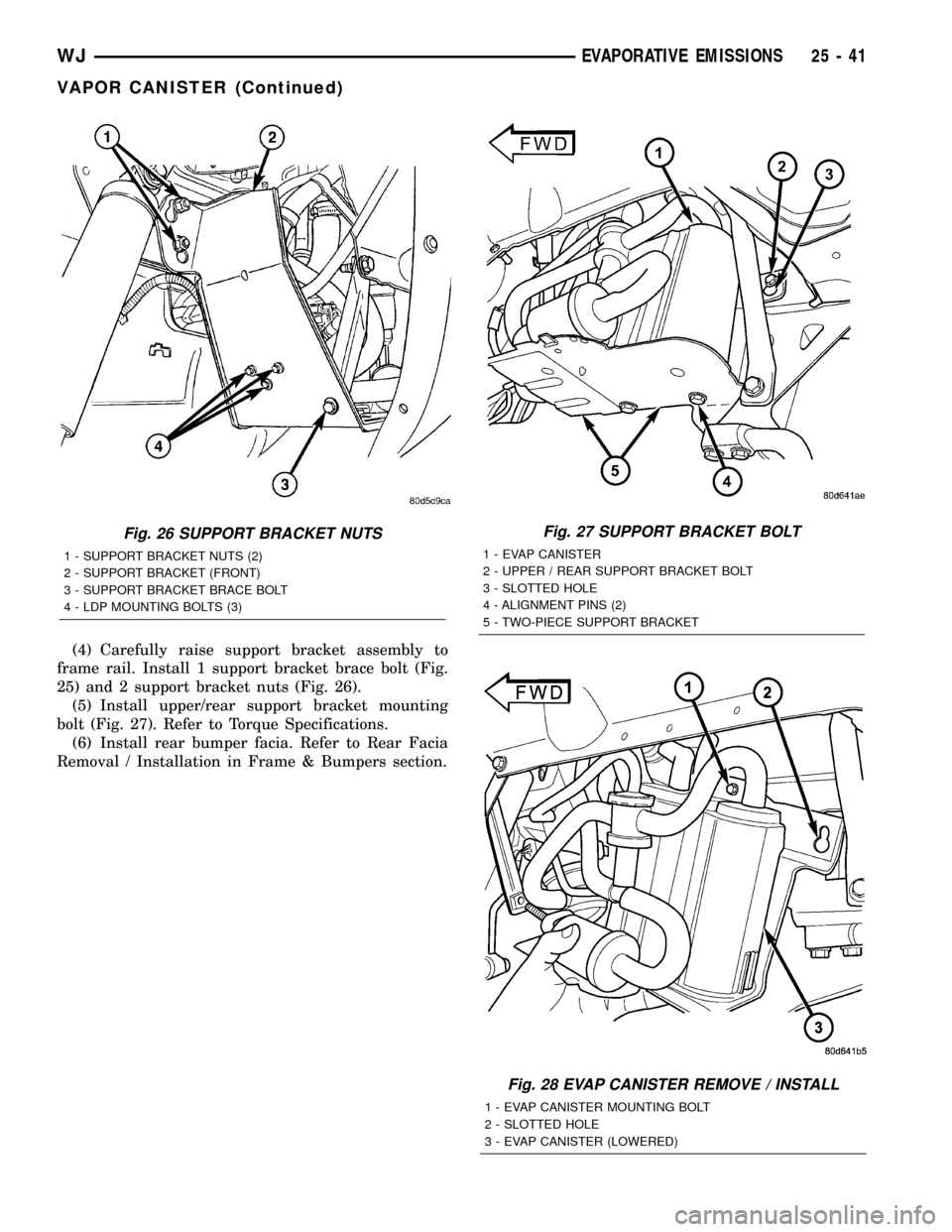
(4) Carefully raise support bracket assembly to
frame rail. Install 1 support bracket brace bolt (Fig.
25) and 2 support bracket nuts (Fig. 26).
(5) Install upper/rear support bracket mounting
bolt (Fig. 27). Refer to Torque Specifications.
(6) Install rear bumper facia. Refer to Rear Facia
Removal / Installation in Frame & Bumpers section.
Fig. 27 SUPPORT BRACKET BOLT
1 - EVAP CANISTER
2 - UPPER / REAR SUPPORT BRACKET BOLT
3 - SLOTTED HOLE
4 - ALIGNMENT PINS (2)
5 - TWO-PIECE SUPPORT BRACKET
Fig. 28 EVAP CANISTER REMOVE / INSTALL
1 - EVAP CANISTER MOUNTING BOLT
2 - SLOTTED HOLE
3 - EVAP CANISTER (LOWERED)
Fig. 26 SUPPORT BRACKET NUTS
1 - SUPPORT BRACKET NUTS (2)
2 - SUPPORT BRACKET (FRONT)
3 - SUPPORT BRACKET BRACE BOLT
4 - LDP MOUNTING BOLTS (3)
WJEVAPORATIVE EMISSIONS 25 - 41
VAPOR CANISTER (Continued)