Gear JEEP GRAND CHEROKEE 2003 WJ / 2.G Workshop Manual
[x] Cancel search | Manufacturer: JEEP, Model Year: 2003, Model line: GRAND CHEROKEE, Model: JEEP GRAND CHEROKEE 2003 WJ / 2.GPages: 2199, PDF Size: 76.01 MB
Page 1848 of 2199

(15) Remove front bearing retainer seal with suit-
able pry tool.
(16) Install new front bearing retainer with
Installer 7884 (Fig. 44).
INPUT AND LOW RANGE GEAR
(1) Lubricate gears and thrust washers (Fig. 45)
with transfer case lubricant.
(2) Install first thrust washer in low range gear
(Fig. 45). Be sure washer tabs are properly aligned in
gear notches.
(3) Install input gear in low range gear. Be sure
input gear is fully seated.
(4) Install remaining thrust washer in low range
gear and on top of input gear. Be sure washer tabs
are properly aligned in gear notches.
(5) Install retainer on input gear and install snap-
ring.
(6) Align and install low range/input gear assem-
bly in front case (Fig. 46). Be sure low range gear
pinions are engaged in annulus gear and that input
gear shaft is fully seated in front bearing.
Fig. 44 Install Front Bearing Retainer Seal
1 - FRONT BEARING RETAINER
2 - SPECIAL TOOL 7884
Fig. 45 Input/Low Range Gear Components
1 - SNAP-RING
2 - RETAINER PLATE
3 - INPUT GEAR
4 - LOW RANGE GEAR
5 - THRUST WASHERS
Fig. 46 Input/Low Range Gear Installation
1 - ANNULUS GEAR
2 - INPUT/LOW RANGE GEAR
WJTRANSFER CASE - NV247 21 - 329
TRANSFER CASE - NV247 (Continued)
Page 1849 of 2199

(7) Install snap-ring to hold input/low range gear
into front bearing (Fig. 47).
(8) Clean gasket sealer residue from retainer and
inspect retainer for cracks or other damage.
(9) Applya3mm(1/8 in.) bead of Mopartgasket
maker or silicone adhesive to sealing surface of
retainer.
(10) Align cavity in seal retainer with fluid return
hole in front of case.
CAUTION: Do not block fluid return cavity on seal-
ing surface of retainer when applying MoparTgas-
ket maker or silicone adhesive sealer. Seal failure
and fluid leak can result.
(11) Install bolts to hold retainer to transfer case
(Fig. 48). Tighten to 21 N´m (16 ft. lbs.) of torque.SHIFT FORKS AND MAINSHAFT
(1) Install new sector shaft O-ring and bushing
(Fig. 49).
(2) Install shift sector (Fig. 50).
(3) Install locking clutch spring, locking clutch,
blockout spring, and range clutch sleeve, to main-
shaft as shown in (Fig. 51). Install snap ring.
(4) Install drive sprocket hub to mainshaft and
manually load the needle bearings.
(5) Install new pads on range fork, if necessary.
Fig. 47 Install Input Gear Snap-Ring
1 - INPUT GEAR
2 - SNAP-RING
Fig. 48 Install Front Bearing Retainer
1 - FRONT BEARING RETAINER
Fig. 49 Sector O-Ring And Bushing Installation
1 - SECTOR BUSHING
2 - O-RING
Fig. 50 Shift Sector Installation
1 - SHIFT SECTOR
21 - 330 TRANSFER CASE - NV247WJ
TRANSFER CASE - NV247 (Continued)
Page 1850 of 2199

(6) Install range shift fork to range clutch sleeve.
Install mainshaft/range shift fork assembly into
transfer case and input planetary assembly. Rotate
fork until it engages with slot in shift sector.
(7) Install shift rail to shift range fork and trans-
fer case housing.
(8) Rotate shift sector to NEUTRAL position.
(9) Install new O-ring on detent plug (Fig. 52).
(10) Lubricate detent plunger with transfer case
lubricant or light coat of petroleum jelly.
(11) Install detent plunger, spring and plug (Fig.
52).
(12)
Verify that plunger is properly engaged in sector.
FRONT OUTPUT SHAFT AND DRIVE CHAIN
(1) Lubricate front output shaft-sprocket assembly,
drive chain and drive sprocket with transfer case
lubricant.
(2) Assemble drive chain, drive sprocket and front
output shaft (Fig. 53).
(3) Start drive sprocket on mainshaft.
(4) Guide front shaft into bearing and drive
sprocket onto mainshaft drive gear (Fig. 53).
(5) Install drive sprocket snap-ring (Fig. 54).
Fig. 51 Range Clutch Sleeve, Blockout Spring,
Locking Clutch and Spring
1 - LOCKING CLUTCH SPRING
2 - BLOCKOUT SPRING
3 - SNAP-RING
4 - RANGE CLUTCH SLEEVE
5 - LOCKING CLUTCH
6 - DRIVE SPROCKET HUB
Fig. 52 Shift Detent Components
1 - DETENT PLUG
2 - DETENT SPRING
3 - DETENT PLUNGER
4 - PLUG O-RING
Fig. 53 Installing Drive Chain, Front Output Shaft
And Drive Sprocket
1 - FRONT OUTPUT SHAFT
2 - DRIVE CHAIN
3 - MAINSHAFT
4 - DRIVE GEAR
WJTRANSFER CASE - NV247 21 - 331
TRANSFER CASE - NV247 (Continued)
Page 2027 of 2199

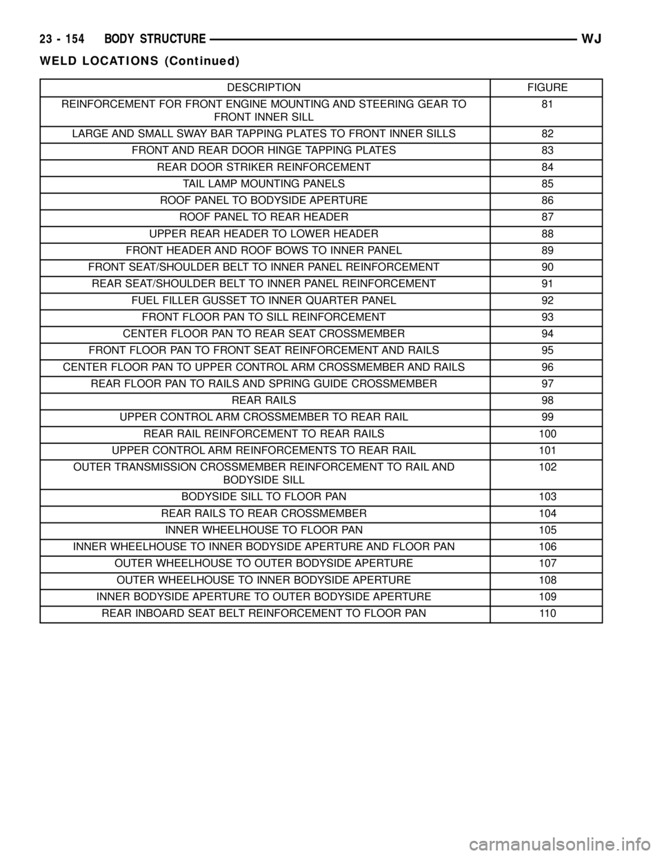
DESCRIPTION FIGURE
REINFORCEMENT FOR FRONT ENGINE MOUNTING AND STEERING GEAR TO
FRONT INNER SILL81
LARGE AND SMALL SWAY BAR TAPPING PLATES TO FRONT INNER SILLS 82
FRONT AND REAR DOOR HINGE TAPPING PLATES 83
REAR DOOR STRIKER REINFORCEMENT 84
TAIL LAMP MOUNTING PANELS 85
ROOF PANEL TO BODYSIDE APERTURE 86
ROOF PANEL TO REAR HEADER 87
UPPER REAR HEADER TO LOWER HEADER 88
FRONT HEADER AND ROOF BOWS TO INNER PANEL 89
FRONT SEAT/SHOULDER BELT TO INNER PANEL REINFORCEMENT 90
REAR SEAT/SHOULDER BELT TO INNER PANEL REINFORCEMENT 91
FUEL FILLER GUSSET TO INNER QUARTER PANEL 92
FRONT FLOOR PAN TO SILL REINFORCEMENT 93
CENTER FLOOR PAN TO REAR SEAT CROSSMEMBER 94
FRONT FLOOR PAN TO FRONT SEAT REINFORCEMENT AND RAILS 95
CENTER FLOOR PAN TO UPPER CONTROL ARM CROSSMEMBER AND RAILS 96
REAR FLOOR PAN TO RAILS AND SPRING GUIDE CROSSMEMBER 97
REAR RAILS 98
UPPER CONTROL ARM CROSSMEMBER TO REAR RAIL 99
REAR RAIL REINFORCEMENT TO REAR RAILS 100
UPPER CONTROL ARM REINFORCEMENTS TO REAR RAIL 101
OUTER TRANSMISSION CROSSMEMBER REINFORCEMENT TO RAIL AND
BODYSIDE SILL102
BODYSIDE SILL TO FLOOR PAN 103
REAR RAILS TO REAR CROSSMEMBER 104
INNER WHEELHOUSE TO FLOOR PAN 105
INNER WHEELHOUSE TO INNER BODYSIDE APERTURE AND FLOOR PAN 106
OUTER WHEELHOUSE TO OUTER BODYSIDE APERTURE 107
OUTER WHEELHOUSE TO INNER BODYSIDE APERTURE 108
INNER BODYSIDE APERTURE TO OUTER BODYSIDE APERTURE 109
REAR INBOARD SEAT BELT REINFORCEMENT TO FLOOR PAN 110
23 - 154 BODY STRUCTUREWJ
WELD LOCATIONS (Continued)
Page 2053 of 2199

Fig. 81 REINFORCEMENT FOR FRONT ENGINE MOUNTING AND STEERING GEAR TO FRONT INNER SILL
23 - 180 BODY STRUCTUREWJ
WELD LOCATIONS (Continued)
Page 2135 of 2199

The high pressure relief valve vents only enough
refrigerant to reduce the system pressure, and then
re-seats itself. The majority of the refrigerant is con-
served in the system. If the valve vents refrigerant, it
does not mean that the valve is faulty.
The high pressure relief valve is a factory-cali-
brated unit. The valve cannot be adjusted or
repaired, and must not be removed or otherwise dis-
turbed. The valve is only serviced as a part of the
compressor assembly.
DIAGNOSIS AND TESTING - COMPRESSOR
NOISE
When investigating an air conditioning related
noise, you must first know the conditions under
which the noise occurs. These conditions include:
weather, vehicle speed, transmission in gear or neu-
tral, engine speed, engine temperature, and any
other special conditions. Noises that develop during
air conditioning operation can often be misleading.
For example: What sounds like a failed front bearing
or connecting rod, may be caused by loose bolts, nuts,
mounting brackets, or a loose compressor clutch
assembly.
Drive belts are speed sensitive. At different engine
speeds and depending upon belt tension, belts can
develop noises that are mistaken for a compressor
noise. Improper belt tension can cause a misleading
noise when the compressor clutch is engaged, which
may not occur when the compressor clutch is disen-
gaged. Check the serpentine drive belt condition and
tension as described in Cooling before beginning this
procedure.
(1) Select a quiet area for testing. Duplicate the
complaint conditions as much as possible. Switch the
compressor on and off several times to clearly iden-
tify the compressor noise. Listen to the compressor
while the clutch is engaged and disengaged. Probe
the compressor with an engine stethoscope or a long
screwdriver with the handle held to your ear to bet-
ter localize the source of the noise.
(2) Loosen all of the compressor mounting hard-
ware and retighten. Tighten the compressor clutch
mounting nut. Be certain that the clutch coil is
mounted securely to the compressor, and that the
clutch plate and pulley are properly aligned and have
the correct air gap. (Refer to 24 - HEATING & AIR
CONDITIONING/CONTROLS/A/C COMPRESSOR
CLUTCH - INSTALLATION)
(3) To duplicate a high-ambient temperature condi-
tion (high head pressure), restrict the air flow
through the condenser. Install a manifold gauge set
to be certain that the discharge pressure does not
exceed 2760 kPa (400 psi).
(4) Check the refrigerant system plumbing for
incorrect routing, rubbing or interference, which cancause unusual noises. Also check the refrigerant lines
for kinks or sharp bends that will restrict refrigerant
flow, which can cause noises. (Refer to 24 - HEAT-
ING & AIR CONDITIONING/PLUMBING - CAU-
TION - REFRIGERANT HOSES/LINES/TUBES
PRECAUTIONS)
(5) If the noise is from opening and closing of the
high pressure relief valve, reclaim, evacuate, and
recharge the refrigerant system. (Refer to 24 - HEAT-
ING & AIR CONDITIONING/PLUMBING - STAN-
DARD PROCEDURE - REFRIGERANT RECOVERY)
(Refer to 24 - HEATING & AIR CONDITIONING/
PLUMBING - STANDARD PROCEDURE - REFRIG-
ERANT SYSTEM EVACUATE) (Refer to 24 -
HEATING & AIR CONDITIONING/PLUMBING -
STANDARD PROCEDURE - REFRIGERANT SYS-
TEM CHARGE)If the high pressure relief valve still
does not seat properly, replace the a/c compressor.
(Refer to 24 - HEATING & AIR CONDITIONING/
PLUMBING/A/C COMPRESSOR - REMOVAL)
(6) If the noise is from liquid slugging on the suc-
tion line, check the refrigerant oil level and the
refrigerant system charge. (Refer to 24 - HEATING
& AIR CONDITIONING/PLUMBING/REFRIGER-
ANT OIL - STANDARD PROCEDURE) (Refer to 24 -
HEATING & AIR CONDITIONING/PLUMBING -
SPECIFICATIONS - CHARGE CAPACITY).
(7) If the noise continues, replace the compressor
and repeat Step 1.
REMOVAL
REMOVAL
The compressor may be removed and repositioned
without disconnecting the refrigerant lines or dis-
charging the refrigerant system. Discharging is not
necessary if servicing the compressor clutch or clutch
coil, the engine, the cylinder head, or the generator.
WARNING: REVIEW THE WARNINGS AND CAU-
TIONS IN THE FRONT OF THIS SECTION BEFORE
PERFORMING THE FOLLOWING OPERATION.
(Refer to 24 - HEATING & AIR CONDITIONING/
PLUMBING - WARNING) (Refer to 24 - HEATING &
AIR CONDITIONING/PLUMBING - CAUTION)
(1) Recover the refrigerant from the system. (Refer
to 24 - HEATING & AIR CONDITIONING/PLUMB-
ING - STANDARD PROCEDURE - REFRIGERANT
RECOVERY)
(2) Disconnect and isolate the battery negative
cable.
(3) Remove the serpentine drive belt. Refer to
Cooling for the procedures.
(4) Unplug the compressor clutch coil wire harness
connector.
24 - 58 PLUMBINGWJ
A/C COMPRESSOR (Continued)
Page 2165 of 2199

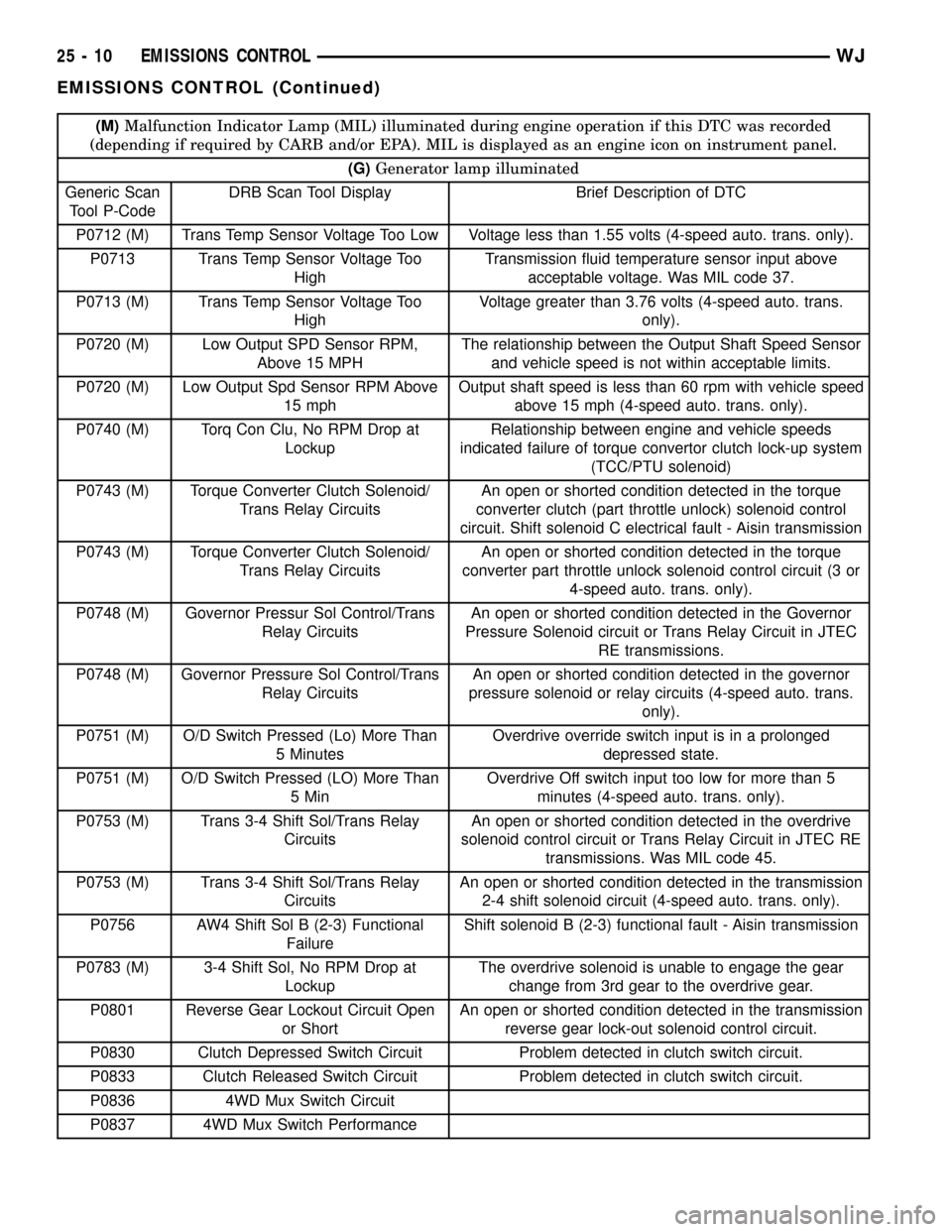
(M)Malfunction Indicator Lamp (MIL) illuminated during engine operation if this DTC was recorded
(depending if required by CARB and/or EPA). MIL is displayed as an engine icon on instrument panel.
(G)Generator lamp illuminated
Generic Scan
Tool P-CodeDRB Scan Tool Display Brief Description of DTC
P0712 (M) Trans Temp Sensor Voltage Too Low Voltage less than 1.55 volts (4-speed auto. trans. only).
P0713 Trans Temp Sensor Voltage Too
HighTransmission fluid temperature sensor input above
acceptable voltage. Was MIL code 37.
P0713 (M) Trans Temp Sensor Voltage Too
HighVoltage greater than 3.76 volts (4-speed auto. trans.
only).
P0720 (M) Low Output SPD Sensor RPM,
Above 15 MPHThe relationship between the Output Shaft Speed Sensor
and vehicle speed is not within acceptable limits.
P0720 (M) Low Output Spd Sensor RPM Above
15 mphOutput shaft speed is less than 60 rpm with vehicle speed
above 15 mph (4-speed auto. trans. only).
P0740 (M) Torq Con Clu, No RPM Drop at
LockupRelationship between engine and vehicle speeds
indicated failure of torque convertor clutch lock-up system
(TCC/PTU solenoid)
P0743 (M) Torque Converter Clutch Solenoid/
Trans Relay CircuitsAn open or shorted condition detected in the torque
converter clutch (part throttle unlock) solenoid control
circuit. Shift solenoid C electrical fault - Aisin transmission
P0743 (M) Torque Converter Clutch Solenoid/
Trans Relay CircuitsAn open or shorted condition detected in the torque
converter part throttle unlock solenoid control circuit (3 or
4-speed auto. trans. only).
P0748 (M) Governor Pressur Sol Control/Trans
Relay CircuitsAn open or shorted condition detected in the Governor
Pressure Solenoid circuit or Trans Relay Circuit in JTEC
RE transmissions.
P0748 (M) Governor Pressure Sol Control/Trans
Relay CircuitsAn open or shorted condition detected in the governor
pressure solenoid or relay circuits (4-speed auto. trans.
only).
P0751 (M) O/D Switch Pressed (Lo) More Than
5 MinutesOverdrive override switch input is in a prolonged
depressed state.
P0751 (M) O/D Switch Pressed (LO) More Than
5 MinOverdrive Off switch input too low for more than 5
minutes (4-speed auto. trans. only).
P0753 (M) Trans 3-4 Shift Sol/Trans Relay
CircuitsAn open or shorted condition detected in the overdrive
solenoid control circuit or Trans Relay Circuit in JTEC RE
transmissions. Was MIL code 45.
P0753 (M) Trans 3-4 Shift Sol/Trans Relay
CircuitsAn open or shorted condition detected in the transmission
2-4 shift solenoid circuit (4-speed auto. trans. only).
P0756 AW4 Shift Sol B (2-3) Functional
FailureShift solenoid B (2-3) functional fault - Aisin transmission
P0783 (M) 3-4 Shift Sol, No RPM Drop at
LockupThe overdrive solenoid is unable to engage the gear
change from 3rd gear to the overdrive gear.
P0801 Reverse Gear Lockout Circuit Open
or ShortAn open or shorted condition detected in the transmission
reverse gear lock-out solenoid control circuit.
P0830 Clutch Depressed Switch Circuit Problem detected in clutch switch circuit.
P0833 Clutch Released Switch Circuit Problem detected in clutch switch circuit.
P0836 4WD Mux Switch Circuit
P0837 4WD Mux Switch Performance
25 - 10 EMISSIONS CONTROLWJ
EMISSIONS CONTROL (Continued)
Page 2170 of 2199

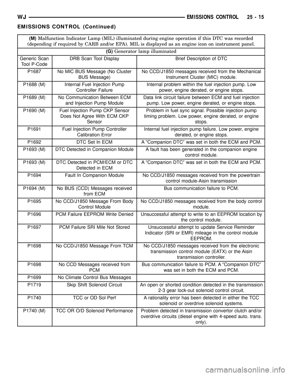
(M)Malfunction Indicator Lamp (MIL) illuminated during engine operation if this DTC was recorded
(depending if required by CARB and/or EPA). MIL is displayed as an engine icon on instrument panel.
(G)Generator lamp illuminated
Generic Scan
Tool P-CodeDRB Scan Tool Display Brief Description of DTC
P1687 No MIC BUS Message (No Cluster
BUS Message)No CCD/J1850 messages received from the Mechanical
Instrument Cluster (MIC) module.
P1688 (M) Internal Fuel Injection Pump
Controller FailureInternal problem within the fuel injection pump. Low
power, engine derated, or engine stops.
P1689 (M) No Communication Between ECM
and Injection Pump ModuleData link circuit failure between ECM and fuel injection
pump. Low power, engine derated, or engine stops.
P1690 (M) Fuel Injection Pump CKP Sensor
Does Not Agree With ECM CKP
SensorProblem in fuel sync signal. Possible injection pump
timing problem. Low power, engine derated, or engine
stops.
P1691 Fuel Injection Pump Controller
Calibration ErrorInternal fuel injection pump failure. Low power, engine
derated, or engine stops.
P1692 DTC Set In ECM A9Companion DTC9was set in both the ECM and PCM.
P1693 (M) DTC Detected in Companion Module A fault has been generated in the companion engine
control module.
P1693 (M) DTC Detected in PCM/ECM or DTC
Detected in ECMA9Companion DTC9was set in both the ECM and PCM.
P1694 Fault In Companion Module No CCD/J1850 messages received from the powertrain
control module-Aisin transmission
P1694 (M) No BUS (CCD) Messages received
from ECMBus communication failure to PCM.
P1695 No CCD/J1850 Message From Body
Control ModuleNo CCD/J1850 messages received from the body control
module.
P1696 PCM Failure EEPROM Write Denied Unsuccessful attempt to write to an EEPROM location by
the control module.
P1697 PCM Failure SRI Mile Not Stored Unsuccessful attempt to update Service Reminder
Indicator (SRI or EMR) mileage in the control module
EEPROM.
P1698 No CCD/J1850 Message From TCM No CCD/J1850 messages received from the electronic
transmission control module (EATX) or the Aisin
transmission controller.
P1698 No CCD Messages received from
PCMBus communication failure to PCM. A9Companion DTC9
was set in both the ECM and PCM.
P1699 No Climate Control Bus Messages
P1719 Skip Shift Solenoid Circuit An open or shorted condition detected in the transmission
2-3 gear lock-out solenoid control circuit.
P1740 TCC or OD Sol Perf A rationality error has been detected in either the TCC
solenoid or overdrive solenoid systems.
P1740 (M) TCC OR O/D Solenoid Performance Problem detected in transmission convertor clutch and/or
overdrive circuits (diesel engine with 4-speed auto. trans.
only).
WJEMISSIONS CONTROL 25 - 15
EMISSIONS CONTROL (Continued)
Page 2171 of 2199

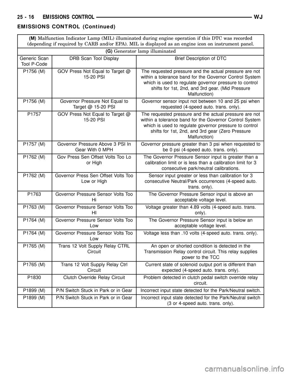
(M)Malfunction Indicator Lamp (MIL) illuminated during engine operation if this DTC was recorded
(depending if required by CARB and/or EPA). MIL is displayed as an engine icon on instrument panel.
(G)Generator lamp illuminated
Generic Scan
Tool P-CodeDRB Scan Tool Display Brief Description of DTC
P1756 (M) GOV Press Not Equal to Target @
15-20 PSIThe requested pressure and the actual pressure are not
within a tolerance band for the Governor Control System
which is used to regulate governor pressure to control
shifts for 1st, 2nd, and 3rd gear. (Mid Pressure
Malfunction)
P1756 (M) Governor Pressure Not Equal to
Target @ 15-20 PSIGovernor sensor input not between 10 and 25 psi when
requested (4-speed auto. trans. only).
P1757 GOV Press Not Equal to Target @
15-20 PSIThe requested pressure and the actual pressure are not
within a tolerance band for the Governor Control System
which is used to regulate governor pressure to control
shifts for 1st, 2nd, and 3rd gear (Zero Pressure
Malfunction)
P1757 (M) Governor Pressure Above 3 PSI In
Gear With 0 MPHGovernor pressure greater than 3 psi when requested to
be 0 psi (4-speed auto. trans. only).
P1762 (M) Gov Press Sen Offset Volts Too Lo
or HighThe Governor Pressure Sensor input is greater than a
calibration limit or is less than a calibration limit for 3
consecutive park/neutral calibrations.
P1762 (M) Governor Press Sen Offset Volts Too
Low or HighSensor input greater or less than calibration for 3
consecutive Neutral/Park occurrences (4-speed auto.
trans. only).
P1763 Governor Pressure Sensor Volts Too
HiThe Governor Pressure Sensor input is above an
acceptable voltage level.
P1763 (M) Governor Pressure Sensor Volts Too
HIVoltage greater than 4.89 volts (4-speed auto. trans.
only).
P1764 (M) Governor Pressure Sensor Volts Too
LowThe Governor Pressure Sensor input is below an
acceptable voltage level.
P1764 (M) Governor Pressure Sensor Volts Too
LowVoltage less than .10 volts (4-speed auto. trans. only).
P1765 (M) Trans 12 Volt Supply Relay CTRL
CircuitAn open or shorted condition is detected in the
Transmission Relay control circuit. This relay supplies
power to the TCC
P1765 (M) Trans 12 Volt Supply Relay Ctrl
CircuitCurrent state of solenoid output port is different than
expected (4-speed auto. trans. only).
P1830 Clutch Override Relay Circuit Problem detected in clutch pedal switch override relay
circuit.
P1899 (M) P/N Switch Stuck in Park or in Gear Incorrect input state detected for the Park/Neutral switch.
P1899 (M) P/N Switch Stuck in Park or in Gear Incorrect input state detected for the Park/Neutral switch
(3 or 4-speed auto. trans. only).
25 - 16 EMISSIONS CONTROLWJ
EMISSIONS CONTROL (Continued)