Index JEEP GRAND CHEROKEE 2003 WJ / 2.G Owner's Guide
[x] Cancel search | Manufacturer: JEEP, Model Year: 2003, Model line: GRAND CHEROKEE, Model: JEEP GRAND CHEROKEE 2003 WJ / 2.GPages: 2199, PDF Size: 76.01 MB
Page 2010 of 2199

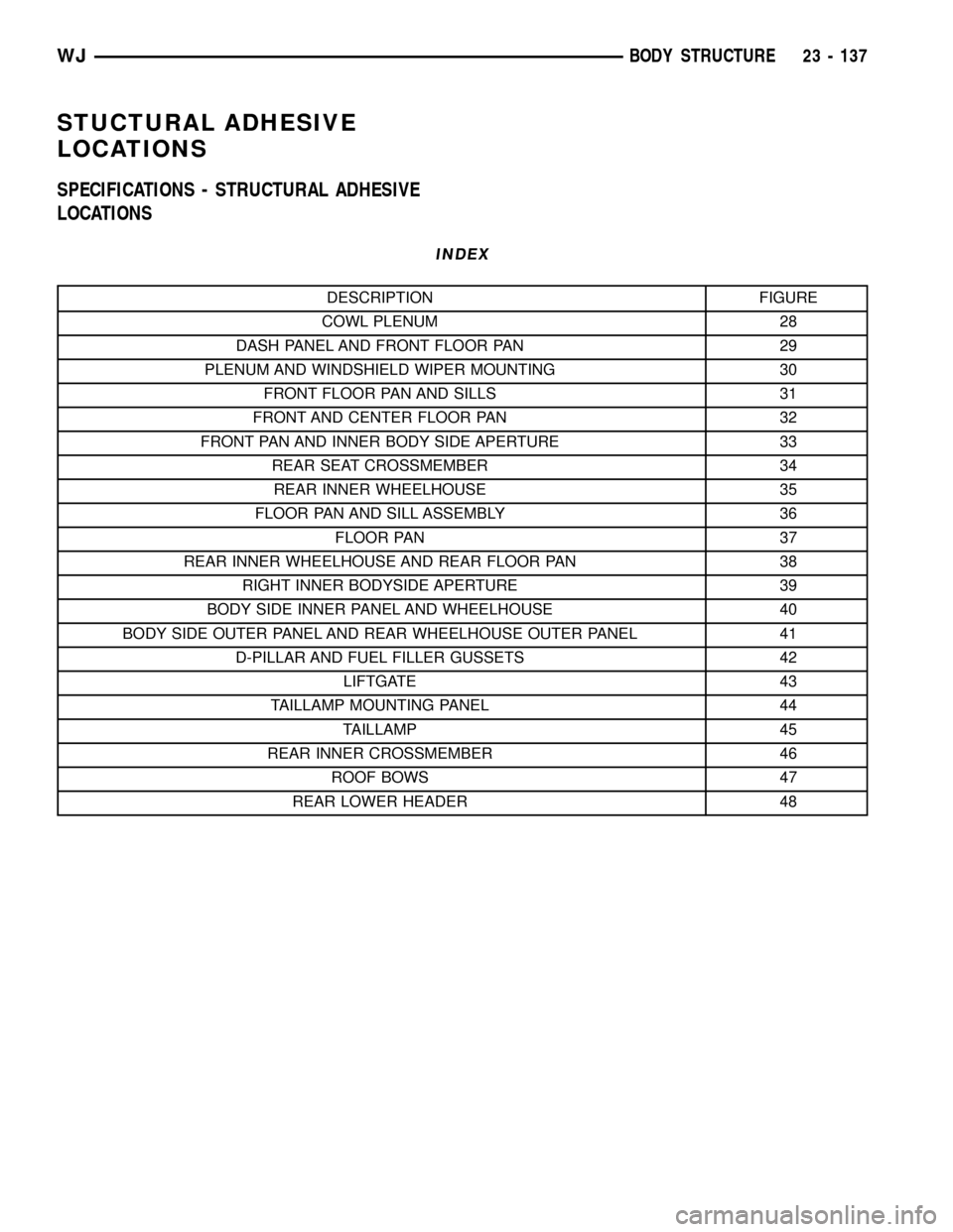
STUCTURAL ADHESIVE
LOCATIONS
SPECIFICATIONS - STRUCTURAL ADHESIVE
LOCATIONS
INDEX
DESCRIPTION FIGURE
COWL PLENUM 28
DASH PANEL AND FRONT FLOOR PAN 29
PLENUM AND WINDSHIELD WIPER MOUNTING 30
FRONT FLOOR PAN AND SILLS 31
FRONT AND CENTER FLOOR PAN 32
FRONT PAN AND INNER BODY SIDE APERTURE 33
REAR SEAT CROSSMEMBER 34
REAR INNER WHEELHOUSE 35
FLOOR PAN AND SILL ASSEMBLY 36
FLOOR PAN 37
REAR INNER WHEELHOUSE AND REAR FLOOR PAN 38
RIGHT INNER BODYSIDE APERTURE 39
BODY SIDE INNER PANEL AND WHEELHOUSE 40
BODY SIDE OUTER PANEL AND REAR WHEELHOUSE OUTER PANEL 41
D-PILLAR AND FUEL FILLER GUSSETS 42
LIFTGATE 43
TAILLAMP MOUNTING PANEL 44
TAILLAMP 45
REAR INNER CROSSMEMBER 46
ROOF BOWS 47
REAR LOWER HEADER 48
WJBODY STRUCTURE 23 - 137
Page 2026 of 2199

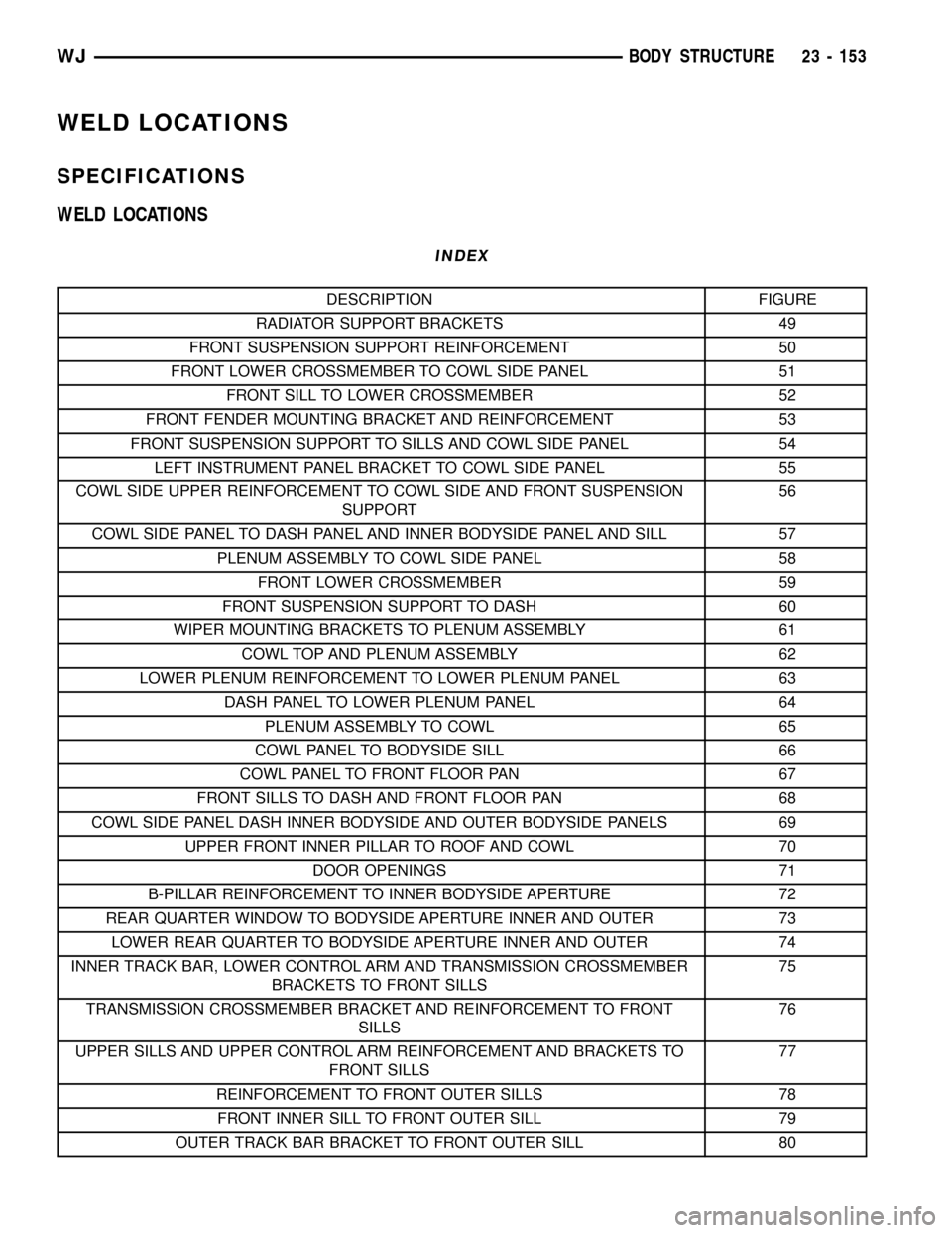
WELD LOCATIONS
SPECIFICATIONS
WELD LOCATIONS
INDEX
DESCRIPTION FIGURE
RADIATOR SUPPORT BRACKETS 49
FRONT SUSPENSION SUPPORT REINFORCEMENT 50
FRONT LOWER CROSSMEMBER TO COWL SIDE PANEL 51
FRONT SILL TO LOWER CROSSMEMBER 52
FRONT FENDER MOUNTING BRACKET AND REINFORCEMENT 53
FRONT SUSPENSION SUPPORT TO SILLS AND COWL SIDE PANEL 54
LEFT INSTRUMENT PANEL BRACKET TO COWL SIDE PANEL 55
COWL SIDE UPPER REINFORCEMENT TO COWL SIDE AND FRONT SUSPENSION
SUPPORT56
COWL SIDE PANEL TO DASH PANEL AND INNER BODYSIDE PANEL AND SILL 57
PLENUM ASSEMBLY TO COWL SIDE PANEL 58
FRONT LOWER CROSSMEMBER 59
FRONT SUSPENSION SUPPORT TO DASH 60
WIPER MOUNTING BRACKETS TO PLENUM ASSEMBLY 61
COWL TOP AND PLENUM ASSEMBLY 62
LOWER PLENUM REINFORCEMENT TO LOWER PLENUM PANEL 63
DASH PANEL TO LOWER PLENUM PANEL 64
PLENUM ASSEMBLY TO COWL 65
COWL PANEL TO BODYSIDE SILL 66
COWL PANEL TO FRONT FLOOR PAN 67
FRONT SILLS TO DASH AND FRONT FLOOR PAN 68
COWL SIDE PANEL DASH INNER BODYSIDE AND OUTER BODYSIDE PANELS 69
UPPER FRONT INNER PILLAR TO ROOF AND COWL 70
DOOR OPENINGS 71
B-PILLAR REINFORCEMENT TO INNER BODYSIDE APERTURE 72
REAR QUARTER WINDOW TO BODYSIDE APERTURE INNER AND OUTER 73
LOWER REAR QUARTER TO BODYSIDE APERTURE INNER AND OUTER 74
INNER TRACK BAR, LOWER CONTROL ARM AND TRANSMISSION CROSSMEMBER
BRACKETS TO FRONT SILLS75
TRANSMISSION CROSSMEMBER BRACKET AND REINFORCEMENT TO FRONT
SILLS76
UPPER SILLS AND UPPER CONTROL ARM REINFORCEMENT AND BRACKETS TO
FRONT SILLS77
REINFORCEMENT TO FRONT OUTER SILLS 78
FRONT INNER SILL TO FRONT OUTER SILL 79
OUTER TRACK BAR BRACKET TO FRONT OUTER SILL 80
WJBODY STRUCTURE 23 - 153
Page 2099 of 2199

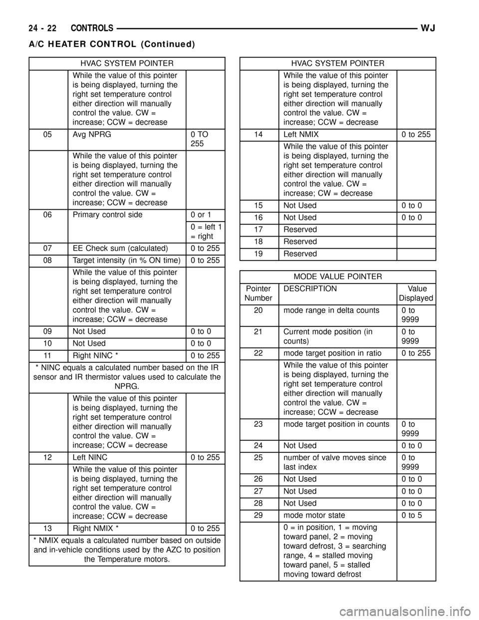
HVAC SYSTEM POINTER
While the value of this pointer
is being displayed, turning the
right set temperature control
either direction will manually
control the value. CW =
increase; CCW = decrease
05 Avg NPRG 0 TO
255
While the value of this pointer
is being displayed, turning the
right set temperature control
either direction will manually
control the value. CW =
increase; CCW = decrease
06 Primary control side 0 or 1
0 = left 1
= right
07 EE Check sum (calculated) 0 to 255
08 Target intensity (in % ON time) 0 to 255
While the value of this pointer
is being displayed, turning the
right set temperature control
either direction will manually
control the value. CW =
increase; CCW = decrease
09 Not Used 0 to 0
10 Not Used 0 to 0
11 Right NINC * 0 to 255
* NINC equals a calculated number based on the IR
sensor and IR thermistor values used to calculate the
NPRG.
While the value of this pointer
is being displayed, turning the
right set temperature control
either direction will manually
control the value. CW =
increase; CCW = decrease
12 Left NINC 0 to 255
While the value of this pointer
is being displayed, turning the
right set temperature control
either direction will manually
control the value. CW =
increase; CCW = decrease
13 Right NMIX * 0 to 255
* NMIX equals a calculated number based on outside
and in-vehicle conditions used by the AZC to position
the Temperature motors.HVAC SYSTEM POINTER
While the value of this pointer
is being displayed, turning the
right set temperature control
either direction will manually
control the value. CW =
increase; CCW = decrease
14 Left NMIX 0 to 255
While the value of this pointer
is being displayed, turning the
right set temperature control
either direction will manually
control the value. CW =
increase; CW = decrease
15 Not Used 0 to 0
16 Not Used 0 to 0
17 Reserved
18 Reserved
19 Reserved
MODE VALUE POINTER
Pointer
NumberDESCRIPTION Value
Displayed
20 mode range in delta counts 0 to
9999
21 Current mode position (in
counts)0to
9999
22 mode target position in ratio 0 to 255
While the value of this pointer
is being displayed, turning the
right set temperature control
either direction will manually
control the value. CW =
increase; CCW = decrease
23 mode target position in counts 0 to
9999
24 Not Used 0 to 0
25 number of valve moves since
last index0to
9999
26 Not Used 0 to 0
27 Not Used 0 to 0
28 Not Used 0 to 0
29 mode motor state 0 to 5
0 = in position, 1 = moving
toward panel, 2 = moving
toward defrost, 3 = searching
range, 4 = stalled moving
toward panel, 5 = stalled
moving toward defrost
24 - 22 CONTROLSWJ
A/C HEATER CONTROL (Continued)
Page 2100 of 2199

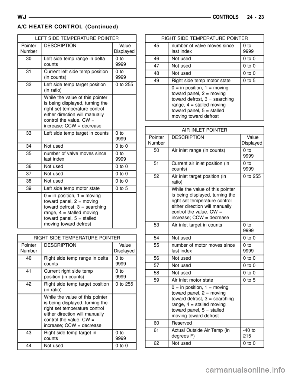
LEFT SIDE TEMPERATURE POINTER
Pointer
NumberDESCRIPTION Value
Displayed
30 Left side temp range in delta
counts0to
9999
31 Current left side temp position
(in counts)0to
9999
32 Left side temp target position
(in ratio)0to255
While the value of this pointer
is being displayed, turning the
right set temperature control
either direction will manually
control the value. CW =
increase; CCW = decrease
33 Left side temp target in counts 0 to
9999
34 Not used 0 to 0
35 number of valve moves since
last index0to
9999
36 Not used 0 to 0
37 Not used 0 to 0
38 Not used 0 to 0
39 Left side temp motor state 0 to 5
0 = in position, 1 = moving
toward panel, 2 = moving
toward defrost, 3 = searching
range, 4 = stalled moving
toward panel, 5 = stalled
moving toward defrost
RIGHT SIDE TEMPERATURE POINTER
Pointer
NumberDESCRIPTION Value
Displayed
40 Right side temp range in delta
counts0to
9999
41 Current right side temp
position (in counts)0to
9999
42 Right side temp target position
(in ratio)0to255
While the value of this pointer
is being displayed, turning the
right set temperature control
either direction will manually
control the value. CW =
increase; CCW = decrease
43 Right side temp target in
counts0to
9999
44 Not used 0 to 0
RIGHT SIDE TEMPERATURE POINTER
45 number of valve moves since
last index0to
9999
46 Not used 0 to 0
47 Not used 0 to 0
48 Not used 0 to 0
49 Right side temp motor state 0 to 5
0 = in position, 1 = moving
toward panel, 2 = moving
toward defrost, 3 = searching
range, 4 = stalled moving
toward panel, 5 = stalled
moving toward defrost
AIR INLET POINTER
Pointer
NumberDESCRIPTION Value
Displayed
50 Air inlet range (in counts) 0 to
9999
51 Current air inlet position (in
counts)0to
9999
52 Air inlet target position (in
ratio)0to255
While the value of this pointer
is being displayed, turning the
right set temperature control
either direction will manually
control the value. CW =
increase; CCW = decrease
53 Air inlet target in counts 0 to
9999
54 Not used 0 to 0
55 number of motor moves since
last index0to
9999
56 Not used 0 to 0
57 Not used 0 to 0
58 Not used 0 to 0
59 Air inlet motor state 0 to 5
0 = in position, 1 = moving
toward panel, 2 = moving
toward defrost, 3 = searching
range, 4 = stalled moving
toward panel, 5 = stalled
moving toward defrost
60 Reserved
61 Actual Outside Air Temp (in
degrees F)-40 to
215
62 Not used 0 to 0
WJCONTROLS 24 - 23
A/C HEATER CONTROL (Continued)
Page 2104 of 2199

REMOVAL
(1) Disconnect and isolate the battery negative
cable.
(2) Depress locking tab and unplug the wire har-
ness connector from the blower motor controller.
(3) Depress locking tab and unplug the controller
connector from the blower motor.
(4) Remove the 2 screws that secure the blower
motor controller to the HVAC housing.
(5) Remove the blower motor controller from the
HVAC housing (Fig. 15).
INSTALLATION
(1) Install the blower motor controller in the
HVAC housing. The housing is indexed to allow con-
troller mounting in only one position. Tighten the
mounting screws to 2.2 N´m (20 in. lbs.).
(2) Plug in the wire harness connector to the
blower motor controller.
(3) Plug in the connector from the blower motor
controller to the blower motor.
(4) Connect the battery negative cable.
BLOWER MOTOR RESISTOR
BLOCK
DESCRIPTION
Models with the standard manual temperature
control system have a blower motor resistor. The
blower motor resistor is mounted to the bottom of the
HVAC housing, under the instrument panel and just
inboard of the blower motor. It can be accessed for
service without removing any other components.
OPERATION
The resistor has multiple resistor wires, each of
which will reduce the current flow to the blower
motor to change the blower motor speed by changing
the resistance in the blower motor ground path. The
blower motor switch directs the ground path through
the correct resistor wire to obtain the selected speed.
With the blower motor switch in the lowest speed
position, the ground path for the motor is applied
through all of the resistor wires. Each higher speed
selected with the blower motor switch applies the
blower motor ground path through fewer of the resis-
tor wires, increasing the blower motor speed. When
the blower motor switch is in the highest speed posi-
tion, the blower motor resistor is bypassed and the
blower motor receives a direct path to ground.
The blower motor resistor cannot be repaired and,
if faulty or damaged, it must be replaced.
DIAGNOSIS AND TESTING - BLOWER MOTOR
RESISTOR BLOCK
For circuit descriptions and diagrams, refer to the
appropriate wiring information.
WARNING: ON VEHICLES EQUIPPED WITH AIR-
BAGS, DISABLE THE AIRBAG SYSTEM BEFORE
ATTEMPTING ANY STEERING WHEEL, STEERING
COLUMN, OR INSTRUMENT PANEL COMPONENT
DIAGNOSIS OR SERVICE. DISCONNECT AND ISO-
LATE THE BATTERY NEGATIVE (GROUND) CABLE,
THEN WAIT TWO MINUTES FOR THE AIRBAG SYS-
TEM CAPACITOR TO DISCHARGE BEFORE PER-
FORMING FURTHER DIAGNOSIS OR SERVICE. THIS
IS THE ONLY SURE WAY TO DISABLE THE AIRBAG
SYSTEM. FAILURE TO TAKE THE PROPER PRE-
CAUTIONS COULD RESULT IN AN ACCIDENTAL
AIRBAG DEPLOYMENT AND POSSIBLE PERSONAL
INJURY.
(1) Disconnect and isolate the battery negative
cable.
(2) Unplug the wire harness connector from the
blower motor resistor.
Fig. 15 BLOWER MOTOR CONTROLLER REMOVE/
INSTALL
1 - BLOWER MOTOR CONTROLLER
2 - BLOWER MOTOR
3 - GROUND STRAP
4 - ELECTRICAL CONNECTORS
5 - HEATER CORE TUBES
WJCONTROLS 24 - 27
BLOWER MOTOR CONTROLLER (Continued)
Page 2105 of 2199

(3) Check for continuity between each of the
blower motor switch input terminals of the resistor
and the resistor output terminal. In each case there
should be continuity. If OK, repair the wire harness
circuits between the blower motor switch and the
blower motor resistor or blower motor as required. If
not OK, replace the faulty blower motor resistor.
REMOVAL
(1) Disconnect and isolate the battery negative
cable.
(2) Depress locking tab and unplug the wire har-
ness connector from the blower motor resistor.
(3) Depress locking tab and unplug the resistor
connector from the blower motor.
(4) Remove the 2 screws that secure the blower
motor resistor to the HVAC housing.
(5) Remove the blower motor resistor from the
HVAC housing (Fig. 16).
INSTALLATION
(1) Install the blower motor resistor in the HVAC
housing. The housing is indexed to allow mounting in
only one position. Tighten the mounting screws to 2.2
N´m (20 in. lbs.).
(2) Plug in the wire harness connector to the
blower motor resistor.(3) Plug in the connector from the blower motor
resistor to the blower motor.
(4) Connect the battery negative cable.
BLOWER MOTOR SWITCH
DESCRIPTION
The A/C Heater blower motor is controlled by a
rotary-type blower motor switch, mounted in the A/C
Heater control panel. On vehicles with manual tem-
perature control systems, the switch allows the selec-
tion of four blower motor speeds, but will only
operate with the ignition switch in the On position
and the A/C Heater mode control switch in any posi-
tion, except Off. On vehicles with the Automatic Zone
Control (AZC) systems, the switch allows the selec-
tion of Lo Auto, Hi Auto, and ten speed settings
between Lo and Hi.
OPERATION
On manual temperature control systems, the
blower motor switch is connected in series with the
blower motor ground path through the a/c heater
mode control switch. The blower motor switch directs
this ground path to the blower motor through the
blower motor resistor wires, or directly to the blower
motor, as required to achieve the selected blower
motor speed.
On AZC systems, the blower motor switch is just
one of many inputs to the AZC control module. In the
manual blower modes, the AZC control module
adjusts the blower motor speed through the blower
motor controller as required to achieve the selected
blower switch position. In the auto blower modes, the
AZC control assembly is programmed to select and
adjust the blower motor speed through the blower
motor controller as required to achieve and maintain
the selected comfort level.
The blower motor switch cannot be repaired and, if
faulty or damaged, it must be replaced. The switch is
serviced only as a part of the a/c heater control
assembly.
DIAGNOSIS AND TESTING - BLOWER MOTOR
SWITCH-MANUAL TEMPERATURE CONTROL
SYSTEM
For circuit descriptions and diagrams, refer to the
appropriate wiring information.
Fig. 16 BLOWER MOTOR RESISTOR REMOVE/
INSTALL
1 - BLOWER MOTOR RESISTOR
2 - BLOWER MOTOR
3 - GROUND STRAP
4 - ELECTRICAL CONNECTORS
5 - HEATER CORE TUBES
24 - 28 CONTROLSWJ
BLOWER MOTOR RESISTOR BLOCK (Continued)
Page 2115 of 2199

(1) Disconnect and isolate the battery negative
cable.
(2) Pinch the connector retainer and unplug the
blower motor wire harness from the blower motor
(Fig. 2).
(3) Remove the three screws that secure the
blower motor and blower wheel assembly to the
HVAC housing, using either a T-25 Torxthead or
flat-bladed screwdriver.
(4) Lower the blower motor and wheel from the
HVAC housing.
(5) Remove the blower wheel retainer clip (Fig. 3).
(6) Remove the wheel from the blower motor shaft.
INSTALLATION
(1) Press the blower wheel hub onto the blower
motor shaft. Be sure the flat on the blower motor
shaft is indexed to the flat on the inside of the blower
wheel hub.
(2) Install the retainer clip over the blower wheel
hub.
(3) Install the blower motor in the HVAC housing
with three mounting screws. Tighten the mounting
screws to 2.2 N´m (20 in. lbs.).
(4) Plug the blower motor wire harness connector
into the blower motor socket.
(5) Connect the battery negative cable.
DEFROSTER DUCTS
REMOVAL
(1) Remove the instrument panel assembly from
the vehicle(Refer to 23 - BODY/INSTRUMENT
PANEL - REMOVAL).
(2) Remove the three screws that secure the
defroster duct to the HVAC unit housing (Fig. 4).
(3) Remove the defroster duct from the HVAC unit
housing.
Fig. 2 BLOWER MOTOR (HOUSING REMOVED
FROM VEHICLE)
1 - BLOWER MOTOR RESISTOR
2 - BLOWER MOTOR
3 - GROUND STRAP
4 - ELECTRICAL CONNECTORS
5 - HEATER CORE TUBES
Fig. 3 BLOWER MOTOR WHEEL REMOVE/INSTALL
1 - BLOWER MOTOR WHEEL
2 - RETAINER CLIP
Fig. 4 HVAC DEFROSTER DUCT
1 - HVAC UNIT HOUSING
2 - INSTRUMENT PANEL
3 - SCREWS
4 - DEFROSTER DUCT
24 - 38 DISTRIBUTIONWJ
BLOWER MOTOR (Continued)