Rotors JEEP GRAND CHEROKEE 2003 WJ / 2.G Owner's Guide
[x] Cancel search | Manufacturer: JEEP, Model Year: 2003, Model line: GRAND CHEROKEE, Model: JEEP GRAND CHEROKEE 2003 WJ / 2.GPages: 2199, PDF Size: 76.01 MB
Page 213 of 2199
(3) Push the cables into the upper suspension arm
brackets.
(4) Install the cable retainer bolts to the rear
spring pads.
(5) Install the ABS sensor wiring harness to the
rear brake cables.
(6) Install the rotors, caliper anchors and brake
calipers.
(7) Install the wheel and tire assemblies.
(8) Remove support and lower the vehicle.
(9) Engage the cable ends into the parking brake
equalizer.
(10) Pull on the lever to release the lock out
spring.
(11) Install center console, (Refer to 23 - BODY/IN-
TERIOR/FLOOR CONSOLE - INSTALLATION).
(12) Fold down the rear carpet cover and rear seat.
(13) Verify parking brake operation.
LEVER
REMOVAL
(1) Remove center console,(Refer to 23 - BODY/IN-
TERIOR/FLOOR CONSOLE - REMOVAL).
(2) Lift up rear seat and carpet covering the park-
ing brake cables.
(3) Place a screw driver through the front cable
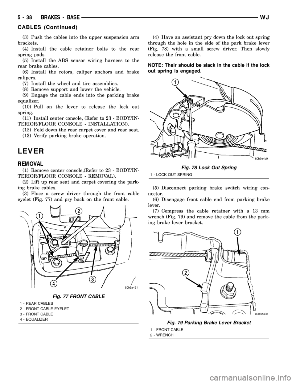
eyelet (Fig. 77) and pry back on the front cable.(4) Have an assistant pry down the lock out spring
through the hole in the side of the park brake lever
(Fig. 78) with a small screw driver. Then slowly
release the front cable.
NOTE: Their should be slack in the cable if the lock
out spring is engaged.
(5) Disconnect parking brake switch wiring con-
nector.
(6) Disengage front cable end from parking brake
lever.
(7) Compress the cable retainer with a 13 mm
wrench (Fig. 79) and remove the cable from the park-
ing brake lever bracket.
Fig. 77 FRONT CABLE
1 - REAR CABLES
2 - FRONT CABLE EYELET
3 - FRONT CABLE
4 - EQUALIZER
Fig. 78 Lock Out Spring
1 - LOCK OUT SPRING
Fig. 79 Parking Brake Lever Bracket
1 - FRONT CABLE
2 - WRENCH
5 - 38 BRAKES - BASEWJ
CABLES (Continued)
Page 251 of 2199
²Fan control valve
²Two stage G-rotor hydraulic drive
The hydraulic fan and drive is not serviceable.
Therefore any failure of the fan blade, hydraulic fan
drive or fan shroud requires replacement of the fan
module because the fan blade and hydraulic fan drive
are matched and balanced as a system and servicing
either separately would disrupt this balance.
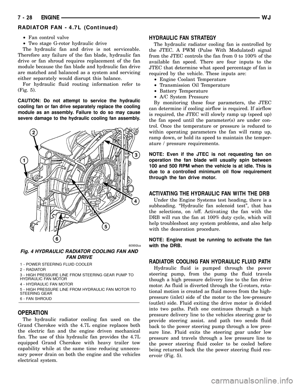
For hydraulic fluid routing information refer to
(Fig. 5).
CAUTION: Do not attempt to service the hydraulic
cooling fan or fan drive separately replace the cooling
module as an assembly. Failure to do so may cause
severe damage to the hydraulic cooling fan assembly.
OPERATION
The hydraulic radiator cooling fan used on the
Grand Cherokee with the 4.7L engine replaces both
the electric fan and the engine driven mechanical
fan. The use of this hydraulic fan provides the 4.7L
equipped Grand Cherokee with heavy trailer tow
capability while at the same time reducing unneces-
sary power drain on both the engine and the vehicles
electrical system.
HYDRAULIC FAN STRATEGY
The hydraulic radiator cooling fan is controlled by
the JTEC. A PWM (Pulse With Modulated) signal
from the JTEC controls the fan from 0 to 100% of the
available fan speed. There are four inputs to the
JTEC that determine what speed percentage of fan is
required by the vehicle. These inputs are:
²Engine Coolant Temperature
²Transmission Oil Temperature
²Battery Temperature
²A/C System Pressure
By monitoring these four parameters, the JTEC
can determine if cooling airflow is required. If airflow
is required, the JTEC will slowly ramp up (speed up)
the fan speed until the parameter(s) are under con-
trol. Once the temperature or pressure is reduced to
within operating parameters the fan will ramp up,
ramp down, or hold its speed to maintain the temper-
ature / pressure requirements.
NOTE: Even if the JTEC is not requesting fan on
operation the fan blade will usually spin between
100 and 500 RPM when the vehicle is at idle. This is
due to a controlled minimum oil flow requirement
through the fan drive motor.
ACTIVATING THE HYDRAULIC FAN WITH THE DRB
Under the Engine Systems test heading, there is a
subheading. ªHydraulic fan solenoid testº, that has
the selections, on /off. Activating the fan with the
DRB will run the fan at 100% duty cycle, which will
help troubleshoot any system problems, and also help
with the deaeration procedure.
NOTE: Engine must be running to activate the fan
with the DRB.
RADIATOR COOLING FAN HYDRAULIC FLUID PATH
Hydraulic fluid is pumped through the power
steering pump, from the pump the fluid travels
though a high pressure delivery line to the fan drive
motor. As fluid is diverted through the G-rotors, rota-
tional motion is created as fluid moves from the high-
pressure (inlet) side of the motor to the low-pressure
(outlet) side. Fluid exiting the drive motor is divided
into two paths. Path one continues through a high
pressure delivery line to the vehicles steering gear to
provide steering assist. and path two sends fluid
back to the power steering pump through a low pres-
sure line. Fluid exits the steering gear under low
pressure and travels through a low pressure line to
the power steering fluid cooler to be cooled before
being returned back the the power steering fluid res-
ervoir (Fig. 5).
Fig. 4 HYDRAULIC RADIATOR COOLING FAN AND
FAN DRIVE
1 - POWER STEERING FLUID COOLER
2 - RADIATOR
3 - HIGH PRESSURE LINE FROM STEERING GEAR PUMP TO
HYDRAULIC FAN MOTOR
4 - HYDRAULIC FAN MOTOR
5 - HIGH PRESSURE LINE FROM HYDRAULIC FAN MOTOR TO
STEERING GEAR
6 - FAN SHROUD
7 - 28 ENGINEWJ
RADIATOR FAN - 4.7L (Continued)
Page 1319 of 2199
DESCRIPTION SPECIFICATION
Exhaust 36.87 - 37.13 mm
1.4516 - 1.4618 in.)
Length (Overall)
Intake 113.45 - 114.21 mm
(4.4666 - 4.4965)
Exhaust 114.92 - 115.68 mm
(4.5244 - 4.5543 in.)
Stem Diameter
Intake 6.931 - 6.957 mm
(0.2729 - 0.2739 in.)
Exhaust 6.902 - 6.928 mm
(0.2717 - 0.2728 in.)
Stem - to - Guide
Clearance
Intake .018 - .069 mm
(0.0008 - 0.0028 in.)
Exhaust .047 - .098 mm
(0.0019 - 0.0039 in.)
Max. Allowable Stem -
to -
Guide Clearance
(Rocking
Method)
Intake 0.069 mm (0.0028 in.)
Exhaust 0.098 mm (0.0039 in.)
Valve Lift (Zero Lash)
Intake 11.25 mm (0.443 in.)
Exhaust 10.90 mm (0.4292 in.)
VALVE SPRING
Free Length (Approx)
Intake and Exhaust 48.6 mm (1.9134 in.)
Spring Force (Valve
Closed)
Intake and Exhaust 315.5 - 352.5 N @ 40.89
mm
(70.92722 - 79.24515 lbs.
@ 1.6099 in.)DESCRIPTION SPECIFICATION
Spring Force (Valve
Open)
Intake and Exhaust 786.0 - 860.0 N @ 29.64
mm
176.6998 - 193.3357 lbs.
@ 1.167 in.)
Number of Coils
Intake and Exhaust 6.69
Wire Diameter
Intake and Exhaust 4.2799 - 4.3561 mm
(0.1685 - 0.1715 in.)
Installed Height (Spring
Seat to Bottom of
Retainer)
Nominal
Intake 40.97 mm (1.613 in.)
Exhaust 40.81 mm (1.606 in.)
CYLINDER HEAD
Gasket Thickness
(Compressed) .7 mm (0.0276 in.)
Valve Seat Angle 44.5É - 45.0É
Valve Seat Runout (MAX) 0.051 mm (0.002 in.)
Valve Seat Width
Intake 1.75 - 2.36 mm
(0.0698 - 0.0928 in.)
Exhaust 1.71 - 2.32 mm
(0.0673 - 0.0911 in.)
Guide Bore Diameter
(Std.)6.975 - 7.00 mm
(0.2747 - 0.2756 in.)
Cylinder Head Warpage
(Flatness) 0.0508 mm (0.002 in.)
OIL PUMP
Clearance Over Rotors /
End Face (MAX).035 - .095 mm
(0.0014 - 0.0038 in.)
Cover Out - of -Flat
(MAX).025 mm (0.001 in.)
Inner and Outer Rotor
Thickness 12.02 mm (0.4731 in.)
9 - 76 ENGINE - 4.7LWJ
ENGINE - 4.7L (Continued)
Page 1320 of 2199
DESCRIPTION SPECIFICATION
Outer Rotor Clearance
(MAX).235 mm (.0093 in.)
Outer Rotor Diameter
(MIN)85.925 mm (0.400 in.)
Tip Clearance Between
Rotors
(MAX) .150 mm (0.006 in.)
OIL PRESSURE
At Curb Idle Speed
(MIN)*25 kPa (4 psi)
@ 3000 rpm 170 - 758 kPa (25 - 110
psi)
* CAUTION: If pressure is zero at curb idle, DO
NOT run
engine at 3000 rpm.
SPECIFICATIONS - 4.7L H.O. ENGINE
DESCRIPTION SPECIFICATION
GENERAL SPECIFICATIONS
Engine Type 90É SOHC V-8 16-Valve
Displacement 4.7 Liters / 4701cc
(287 Cubic Inches)
Bore 93.0 mm (3.66 in.)
Stroke 86.5 mm (3.40 in.)
Compression Ratio 9.7:1
Horsepower 270 BHP @ 5100 RPM
Torque 330 LB-FT @ 3600 RPM
Lead Cylinder #1 Left Bank
Firing Order 1-8-4-3-6-5-7-2
CYLINDER BLOCK
Cylinder Block Cast Iron
Bore Diameter 93.010 .0075 mm
(3.6619 0.0003 in.)
Out of Round (MAX) 0.076 mm (0.003 in.)
Taper (MAX) 0.051 mm (0.002 in.)
PISTONS
Material Aluminum Alloy
Diameter 92.975 mm (3.6605 in.)
Weight 383.5 grams (13.52 oz)
Ring Groove Diameter
No. 1 83.37 - 83.13 mm
(3.296 - 3.269 in.)
DESCRIPTION SPECIFICATION
No. 2 82.833 - 83.033 mm
(3.261 - 3.310 in.)
No. 3 83.88 - 84.08 mm
(3.302 - 3.310 in.)
PISTON PINS
Type Full Floating
Clearance In Piston 0.010 - 0.019 mm
(0.0004 - 0.0008 in.)
Clearance in Rod 0.006 - 0.015 mm
(0.0002 - 0.0005 in.)
Diameter 24.017 - 24.020 mm
(0.9455 - 0.9456 in.)
PISTON RINGS
Ring Gap
Top Compression Ring 0.37 - 0.63 mm
(0.0146 - 0.0249 in.)
Second Compression
Ring0.37 - 0.63 mm
(0.0146 - 0.0249 in.)
Oil Control (Steel Rails) 0.25 - 0.76 mm
(0.0099 - 0.30 in.)
Side Clearance
Top Compression Ring .051 - .094 mm
(0.0020 - 0.0037 in.)
Second Compression
Ring0.040 - 0.080 mm
(0.0016 - 0.0031 in.)
Oil Ring (Steel Ring) .019 - .229 mm
(.0007 - .0091 in.)
Ring Width
Top Compression Ring 1.472 - 1.490 mm
(0.057 - 0.058 in.)
Second Compression
Ring1.472 - 1.490 mm
(0.057 - 0.058 in.)
Oil Ring (Steel Rails) 0.445 - 0.470 mm
(0.017 - 0.018 in.)
CONNECTING RODS
Bearing Clearance 0.010 - 0.048 mm
(0.0004 - 0.0019 in.)
WJENGINE - 4.7L 9 - 77
ENGINE - 4.7L (Continued)
Page 1322 of 2199
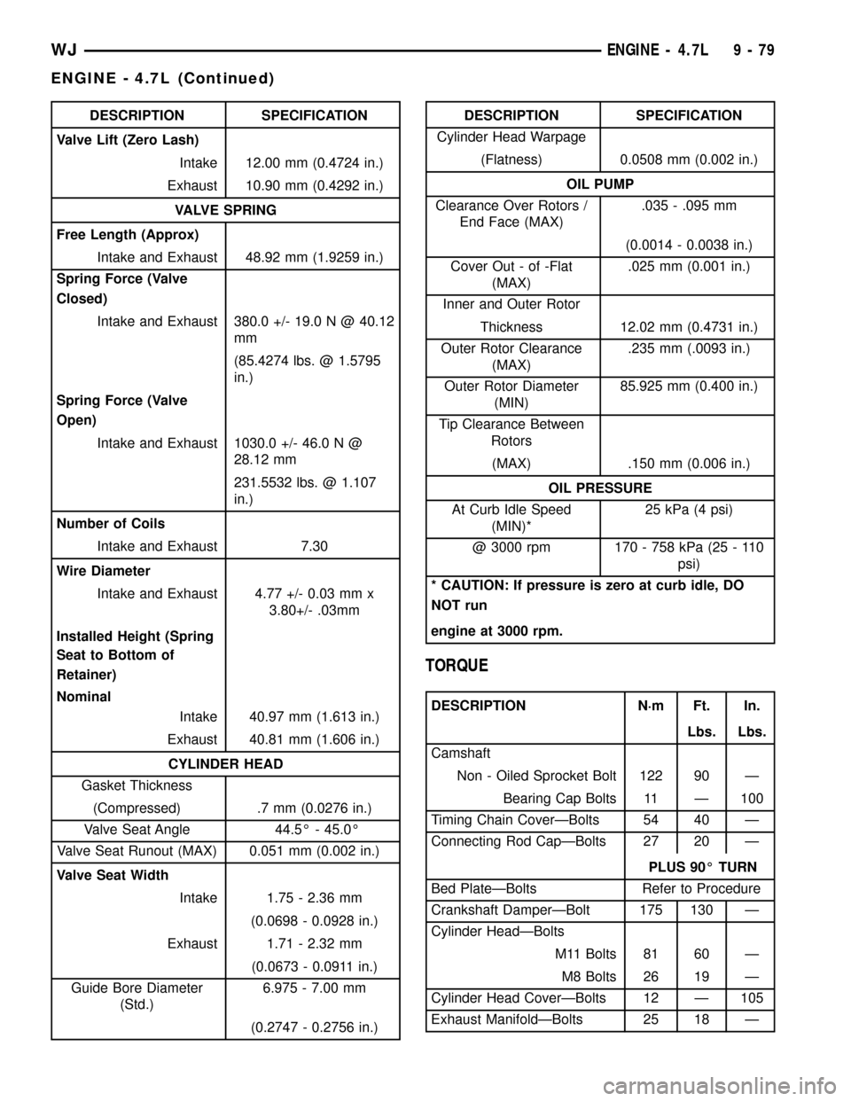
DESCRIPTION SPECIFICATION
Valve Lift (Zero Lash)
Intake 12.00 mm (0.4724 in.)
Exhaust 10.90 mm (0.4292 in.)
VALVE SPRING
Free Length (Approx)
Intake and Exhaust 48.92 mm (1.9259 in.)
Spring Force (Valve
Closed)
Intake and Exhaust 380.0 +/- 19.0 N @ 40.12
mm
(85.4274 lbs. @ 1.5795
in.)
Spring Force (Valve
Open)
Intake and Exhaust 1030.0 +/- 46.0 N @
28.12 mm
231.5532 lbs. @ 1.107
in.)
Number of Coils
Intake and Exhaust 7.30
Wire Diameter
Intake and Exhaust 4.77 +/- 0.03 mm x
3.80+/- .03mm
Installed Height (Spring
Seat to Bottom of
Retainer)
Nominal
Intake 40.97 mm (1.613 in.)
Exhaust 40.81 mm (1.606 in.)
CYLINDER HEAD
Gasket Thickness
(Compressed) .7 mm (0.0276 in.)
Valve Seat Angle 44.5É - 45.0É
Valve Seat Runout (MAX) 0.051 mm (0.002 in.)
Valve Seat Width
Intake 1.75 - 2.36 mm
(0.0698 - 0.0928 in.)
Exhaust 1.71 - 2.32 mm
(0.0673 - 0.0911 in.)
Guide Bore Diameter
(Std.)6.975 - 7.00 mm
(0.2747 - 0.2756 in.)DESCRIPTION SPECIFICATION
Cylinder Head Warpage
(Flatness) 0.0508 mm (0.002 in.)
OIL PUMP
Clearance Over Rotors /
End Face (MAX).035 - .095 mm
(0.0014 - 0.0038 in.)
Cover Out - of -Flat
(MAX).025 mm (0.001 in.)
Inner and Outer Rotor
Thickness 12.02 mm (0.4731 in.)
Outer Rotor Clearance
(MAX).235 mm (.0093 in.)
Outer Rotor Diameter
(MIN)85.925 mm (0.400 in.)
Tip Clearance Between
Rotors
(MAX) .150 mm (0.006 in.)
OIL PRESSURE
At Curb Idle Speed
(MIN)*25 kPa (4 psi)
@ 3000 rpm 170 - 758 kPa (25 - 110
psi)
* CAUTION: If pressure is zero at curb idle, DO
NOT run
engine at 3000 rpm.
TORQUE
DESCRIPTION N´m Ft. In.
Lbs. Lbs.
Camshaft
Non - Oiled Sprocket Bolt 122 90 Ð
Bearing Cap Bolts 11 Ð 100
Timing Chain CoverÐBolts 54 40 Ð
Connecting Rod CapÐBolts 27 20 Ð
PLUS 90É TURN
Bed PlateÐBolts Refer to Procedure
Crankshaft DamperÐBolt 175 130 Ð
Cylinder HeadÐBolts
M11 Bolts 81 60 Ð
M8 Bolts 26 19 Ð
Cylinder Head CoverÐBolts 12 Ð 105
Exhaust ManifoldÐBolts 25 18 Ð
WJENGINE - 4.7L 9 - 79
ENGINE - 4.7L (Continued)
Page 1377 of 2199
OIL PUMP
REMOVAL
(1) Remove the oil pan and pick-up tube (Refer to
9 - ENGINE/LUBRICATION/OIL PAN - REMOVAL).
(2) Remove the timing chain cover (Refer to 9 -
ENGINE/VALVE TIMING/TIMING BELT / CHAIN
COVER(S) - REMOVAL).
(3) Remove the timing chains and tensioners
(Refer to 9 - ENGINE/VALVE TIMING/TIMING
BELT/CHAIN AND SPROCKETS - REMOVAL).
(4) Remove the four bolts, primary timing chain
tensioner and the oil pump.
DISASSEMBLY
(1) Remove oil pump cover screws and lift off cover
plate.
(2) Remove pump inner and outer rotors.
NOTE: Once the oil pressure relief valve, cup plug,
and pin are removed, the pump assembly must be
replaced.
(3) If it is necessary to remove the pressure relief
valve, drive the roll pin from pump housing and
remove cup plug, spring and valve.
CLEANING
(1) Wash all parts in a suitable solvent.
INSPECTION
CAUTION: Oil pump pressure relief valve and
spring should not be removed from the oil pump. If
these components are disassembled and or
removed from the pump the entire oil pump assem-
bly must be replaced.
(1) Clean all parts thoroughly. Mating surface of
the oil pump housing should be smooth. If the pump
cover is scratched or grooved the oil pump assembly
should be replaced.
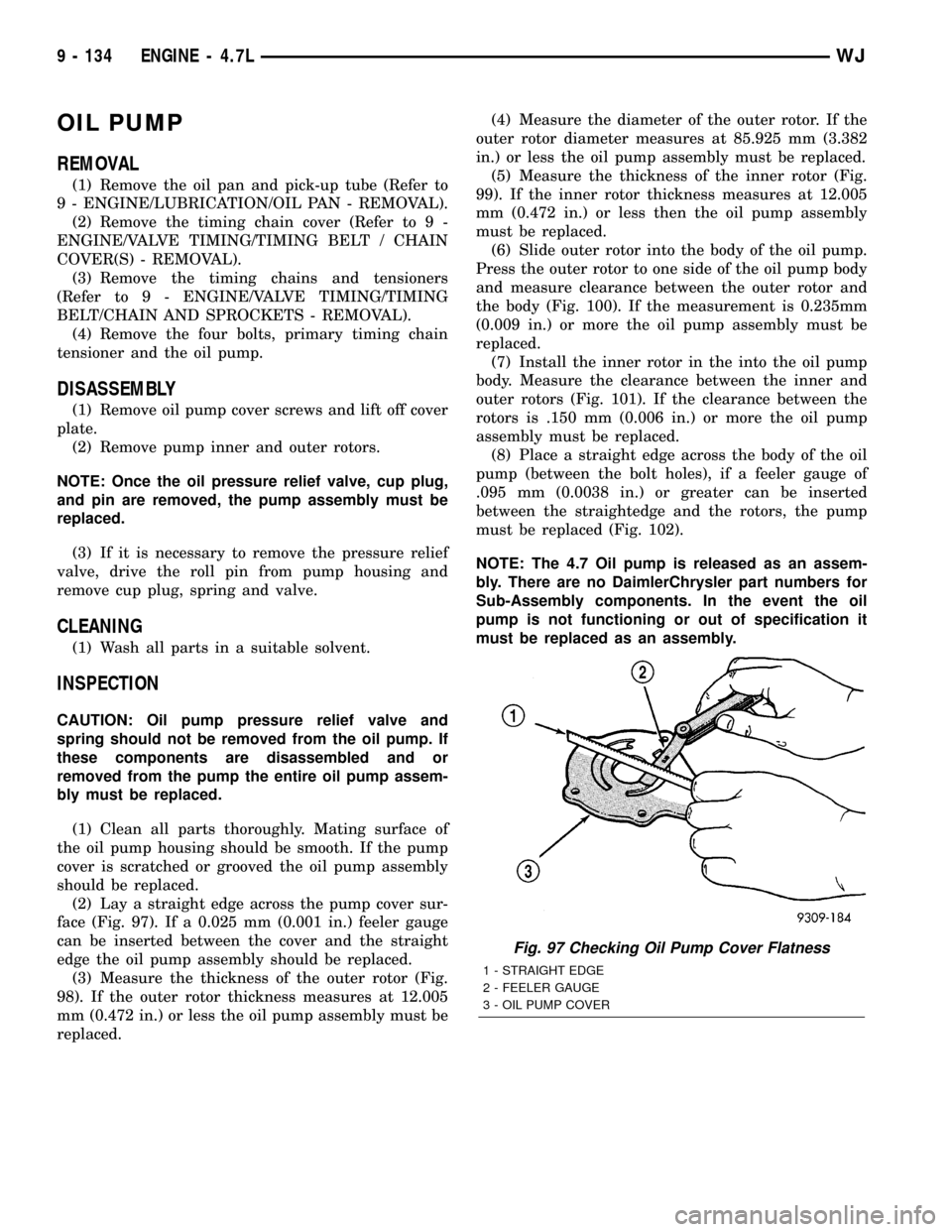
(2) Lay a straight edge across the pump cover sur-
face (Fig. 97). If a 0.025 mm (0.001 in.) feeler gauge
can be inserted between the cover and the straight
edge the oil pump assembly should be replaced.
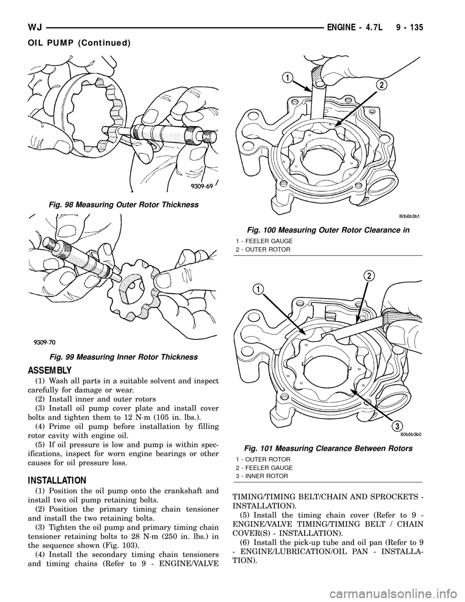
(3) Measure the thickness of the outer rotor (Fig.
98). If the outer rotor thickness measures at 12.005
mm (0.472 in.) or less the oil pump assembly must be
replaced.(4) Measure the diameter of the outer rotor. If the
outer rotor diameter measures at 85.925 mm (3.382
in.) or less the oil pump assembly must be replaced.
(5) Measure the thickness of the inner rotor (Fig.
99). If the inner rotor thickness measures at 12.005
mm (0.472 in.) or less then the oil pump assembly
must be replaced.
(6) Slide outer rotor into the body of the oil pump.
Press the outer rotor to one side of the oil pump body
and measure clearance between the outer rotor and
the body (Fig. 100). If the measurement is 0.235mm
(0.009 in.) or more the oil pump assembly must be
replaced.
(7) Install the inner rotor in the into the oil pump
body. Measure the clearance between the inner and
outer rotors (Fig. 101). If the clearance between the
rotors is .150 mm (0.006 in.) or more the oil pump
assembly must be replaced.
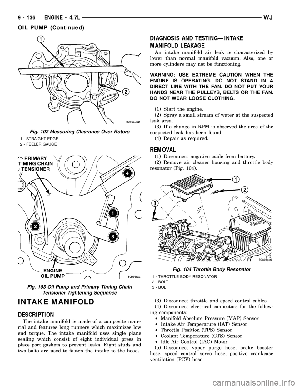
(8) Place a straight edge across the body of the oil
pump (between the bolt holes), if a feeler gauge of
.095 mm (0.0038 in.) or greater can be inserted
between the straightedge and the rotors, the pump
must be replaced (Fig. 102).
NOTE: The 4.7 Oil pump is released as an assem-
bly. There are no DaimlerChrysler part numbers for
Sub-Assembly components. In the event the oil
pump is not functioning or out of specification it
must be replaced as an assembly.
Fig. 97 Checking Oil Pump Cover Flatness
1 - STRAIGHT EDGE
2 - FEELER GAUGE
3 - OIL PUMP COVER
9 - 134 ENGINE - 4.7LWJ
Page 1378 of 2199
ASSEMBLY
(1) Wash all parts in a suitable solvent and inspect
carefully for damage or wear.
(2) Install inner and outer rotors
(3) Install oil pump cover plate and install cover
bolts and tighten them to 12 N´m (105 in. lbs.).
(4) Prime oil pump before installation by filling
rotor cavity with engine oil.
(5) If oil pressure is low and pump is within spec-
ifications, inspect for worn engine bearings or other
causes for oil pressure loss.
INSTALLATION
(1) Position the oil pump onto the crankshaft and
install two oil pump retaining bolts.
(2) Position the primary timing chain tensioner
and install the two retaining bolts.
(3) Tighten the oil pump and primary timing chain
tensioner retaining bolts to 28 N´m (250 in. lbs.) in
the sequence shown (Fig. 103).
(4) Install the secondary timing chain tensioners
and timing chains (Refer to 9 - ENGINE/VALVETIMING/TIMING BELT/CHAIN AND SPROCKETS -
INSTALLATION).
(5) Install the timing chain cover (Refer to 9 -
ENGINE/VALVE TIMING/TIMING BELT / CHAIN
COVER(S) - INSTALLATION).
(6) Install the pick-up tube and oil pan (Refer to 9
- ENGINE/LUBRICATION/OIL PAN - INSTALLA-
TION).
Fig. 98 Measuring Outer Rotor Thickness
Fig. 99 Measuring Inner Rotor Thickness
Fig. 100 Measuring Outer Rotor Clearance in
1 - FEELER GAUGE
2 - OUTER ROTOR
Fig. 101 Measuring Clearance Between Rotors
1 - OUTER ROTOR
2 - FEELER GAUGE
3 - INNER ROTOR
WJENGINE - 4.7L 9 - 135
OIL PUMP (Continued)
Page 1379 of 2199
INTAKE MANIFOLD
DESCRIPTION
The intake manifold is made of a composite mate-
rial and features long runners which maximizes low
end torque. The intake manifold uses single plane
sealing which consist of eight individual press in
place port gaskets to prevent leaks. Eight studs and
two bolts are used to fasten the intake to the head.
DIAGNOSIS AND TESTINGÐINTAKE
MANIFOLD LEAKAGE
An intake manifold air leak is characterized by
lower than normal manifold vacuum. Also, one or
more cylinders may not be functioning.
WARNING: USE EXTREME CAUTION WHEN THE
ENGINE IS OPERATING. DO NOT STAND IN A
DIRECT LINE WITH THE FAN. DO NOT PUT YOUR
HANDS NEAR THE PULLEYS, BELTS OR THE FAN.
DO NOT WEAR LOOSE CLOTHING.
(1) Start the engine.
(2) Spray a small stream of water at the suspected
leak area.
(3) If a change in RPM is observed the area of the
suspected leak has been found.
(4) Repair as required.
REMOVAL
(1) Disconnect negative cable from battery.
(2) Remove air cleaner housing and throttle body
resonator (Fig. 104).
(3) Disconnect throttle and speed control cables.
(4) Disconnect electrical connectors for the follow-
ing components:
²Manifold Absolute Pressure (MAP) Sensor
²Intake Air Temperature (IAT) Sensor
²Throttle Position (TPS) Sensor
²Coolant Temperature (CTS) Sensor
²Idle Air Control (IAC) Motor
(5) Disconnect vapor purge hose, brake booster
hose, speed control servo hose, positive crankcase
ventilation (PCV) hose.
Fig. 102 Measuring Clearance Over Rotors
1 - STRAIGHT EDGE
2 - FEELER GAUGE
Fig. 103 Oil Pump and Primary Timing Chain
Tensioner Tightening Sequence
Fig. 104 Throttle Body Resonator
1 - THROTTLE BODY RESONATOR
2 - BOLT
3 - BOLT
9 - 136 ENGINE - 4.7LWJ
OIL PUMP (Continued)
Page 1509 of 2199
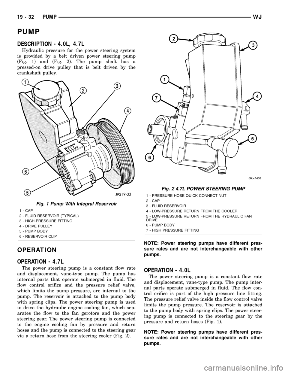
PUMP
DESCRIPTION - 4.0L, 4.7L
Hydraulic pressure for the power steering system
is provided by a belt driven power steering pump
(Fig. 1) and (Fig. 2). The pump shaft has a
pressed-on drive pulley that is belt driven by the
crankshaft pulley.
OPERATION
OPERATION - 4.7L
The power steering pump is a constant flow rate
and displacement, vane-type pump. The pump has
internal parts that operate submerged in fluid. The
flow control orifice and the pressure relief valve,
which limits the pump pressure, are internal to the
pump. The reservoir is attached to the pump body
with spring clips. The power steering pump is used
to drive the hydraulic engine cooling fan, which sep-
arates the flow to the fan gerotors and the power
steering gear. The power steering pump is connected
to the engine cooling fan by pressure and return
hoses and the pump is connected to the steering gear
via a return hose from the steering cooler (Fig. 2).NOTE: Power steering pumps have different pres-
sure rates and are not interchangeable with other
pumps.OPERATION - 4.0L
The power steering pump is a constant flow rate
and displacement, vane-type pump. The pump inter-
nal parts operate submerged in fluid. The flow con-
trol orifice is part of the high pressure line fitting.
The pressure relief valve inside the flow control valve
limits the pump pressure. The reservoir is attached
to the pump body with spring clips. The power steer-
ing pump is connected to the steering gear by the
pressure and return hoses (Fig. 1).
NOTE: Power steering pumps have different pres-
sure rates and are not interchangeable with other
pumps.
Fig. 1 Pump With Integral Reservoir
1 - CAP
2 - FLUID RESERVOIR (TYPICAL)
3 - HIGH-PRESSURE FITTING
4 - DRIVE PULLEY
5 - PUMP BODY
6 - RESERVOIR CLIP
Fig. 2 4.7L POWER STEERING PUMP
1 - PRESSURE HOSE QUICK CONNECT NUT
2 - CAP
3 - FLUID RESERVOIR
4 - LOW-PRESSURE RETURN FROM THE COOLER
5 - LOW-PRESSURE RETURN FROM THE HYDRAULIC FAN
DRIVE
6 - PUMP BODY
7 - HIGH PRESSURE FITTING
19 - 32 PUMPWJ
Page 1870 of 2199
²Bent or dented
²Leak air through welds
²Have damaged bolt holes
Wheel repairs employing hammering, heating, or
welding are not allowed.
Original equipment wheels are available through
your dealer. Replacement wheels from any other
source should be equivalent in:
²Load carrying capacity
²Diameter
²Width²Offset
²Mounting configuration
Failure to use equivalent replacement wheels may
affect the safety and handling of your vehicle.
Replacement withusedwheels is not recommended.
Their service history may have included severe treat-
ment.
SPECIFICATIONS
TORQUE CHART
TORQUE SPECIFICATIONS
DESCRIPTION N´m Ft. Lbs. In. Lbs.
Lug Nut
1/2 X 20 with 60É Cone115-150 85-115 Ð
STUDS
REMOVAL
CAUTION: Do not use a hammer to remove wheel
studs.
(1) Raise and support vehicle.
(2) Remove wheel and tire assembly.
(3) Remove brake caliper, caliper adapter and
rotor,(Refer to 5 - BRAKES/HYDRAULIC/MECHAN-
ICAL/ROTORS - REMOVAL).
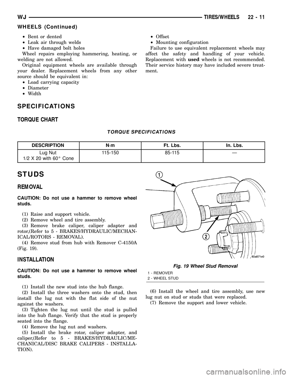
(4) Remove stud from hub with Remover C-4150A
(Fig. 19).
INSTALLATION
CAUTION: Do not use a hammer to remove wheel
studs.
(1) Install the new stud into the hub flange.
(2) Install the three washers onto the stud, then
install the lug nut with the flat side of the nut
against the washers.
(3) Tighten the lug nut until the stud is pulled
into the hub flange. Verify that the stud is properly
seated into the flange.
(4) Remove the lug nut and washers.
(5) Install the brake rotor, caliper adapter, and
caliper,(Refer to 5 - BRAKES/HYDRAULIC/ME-
CHANICAL/DISC BRAKE CALIPERS - INSTALLA-
TION).(6) Install the wheel and tire assembly, use new
lug nut on stud or studs that were replaced.
(7) Remove the support and lower vehicle.Fig. 19 Wheel Stud Removal
1 - REMOVER
2 - WHEEL STUD
WJTIRES/WHEELS 22 - 11
WHEELS (Continued)