Suspension JEEP GRAND CHEROKEE 2003 WJ / 2.G Owner's Guide
[x] Cancel search | Manufacturer: JEEP, Model Year: 2003, Model line: GRAND CHEROKEE, Model: JEEP GRAND CHEROKEE 2003 WJ / 2.GPages: 2199, PDF Size: 76.01 MB
Page 187 of 2199
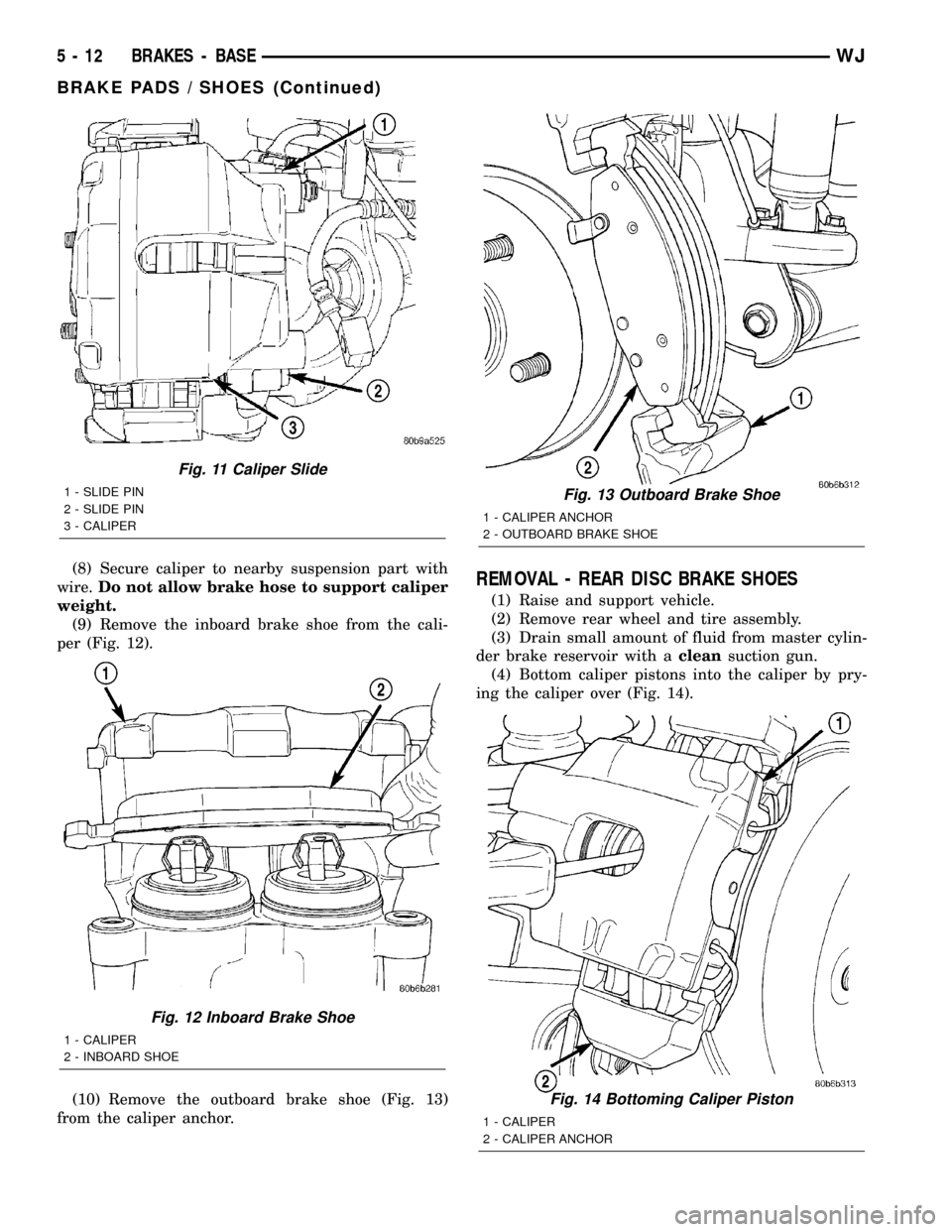
(8) Secure caliper to nearby suspension part with
wire.Do not allow brake hose to support caliper
weight.
(9) Remove the inboard brake shoe from the cali-
per (Fig. 12).
(10) Remove the outboard brake shoe (Fig. 13)
from the caliper anchor.REMOVAL - REAR DISC BRAKE SHOES
(1) Raise and support vehicle.
(2) Remove rear wheel and tire assembly.
(3) Drain small amount of fluid from master cylin-
der brake reservoir with acleansuction gun.
(4) Bottom caliper pistons into the caliper by pry-
ing the caliper over (Fig. 14).
Fig. 11 Caliper Slide
1 - SLIDE PIN
2 - SLIDE PIN
3 - CALIPER
Fig. 12 Inboard Brake Shoe
1 - CALIPER
2 - INBOARD SHOE
Fig. 13 Outboard Brake Shoe
1 - CALIPER ANCHOR
2 - OUTBOARD BRAKE SHOE
Fig. 14 Bottoming Caliper Piston
1 - CALIPER
2 - CALIPER ANCHOR
5 - 12 BRAKES - BASEWJ
BRAKE PADS / SHOES (Continued)
Page 188 of 2199
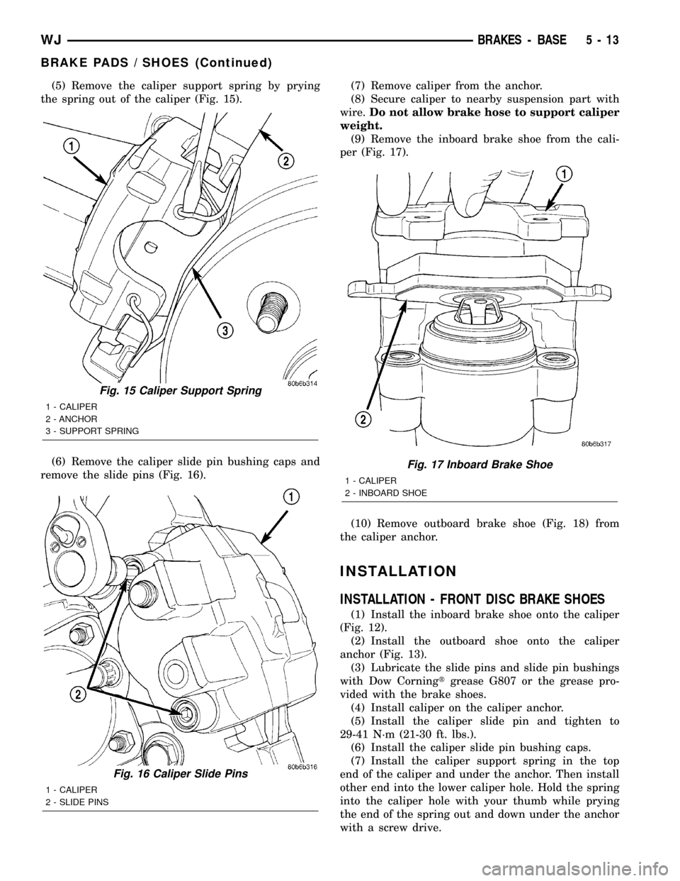
(5) Remove the caliper support spring by prying
the spring out of the caliper (Fig. 15).
(6) Remove the caliper slide pin bushing caps and
remove the slide pins (Fig. 16).(7) Remove caliper from the anchor.
(8) Secure caliper to nearby suspension part with
wire.Do not allow brake hose to support caliper
weight.
(9) Remove the inboard brake shoe from the cali-
per (Fig. 17).
(10) Remove outboard brake shoe (Fig. 18) from
the caliper anchor.
INSTALLATION
INSTALLATION - FRONT DISC BRAKE SHOES
(1) Install the inboard brake shoe onto the caliper
(Fig. 12).
(2) Install the outboard shoe onto the caliper
anchor (Fig. 13).
(3) Lubricate the slide pins and slide pin bushings
with Dow Corningtgrease G807 or the grease pro-
vided with the brake shoes.
(4) Install caliper on the caliper anchor.
(5) Install the caliper slide pin and tighten to
29-41 N´m (21-30 ft. lbs.).
(6) Install the caliper slide pin bushing caps.
(7) Install the caliper support spring in the top
end of the caliper and under the anchor. Then install
other end into the lower caliper hole. Hold the spring
into the caliper hole with your thumb while prying
the end of the spring out and down under the anchor
with a screw drive.
Fig. 15 Caliper Support Spring
1 - CALIPER
2 - ANCHOR
3 - SUPPORT SPRING
Fig. 16 Caliper Slide Pins
1 - CALIPER
2 - SLIDE PINS
Fig. 17 Inboard Brake Shoe
1 - CALIPER
2 - INBOARD SHOE
WJBRAKES - BASE 5 - 13
BRAKE PADS / SHOES (Continued)
Page 212 of 2199
(7) Raise and support the vehicle.
(8) Remove the wheel and tire assemblies.
(9) Remove the brake calipers, caliper anchors and
rotors.
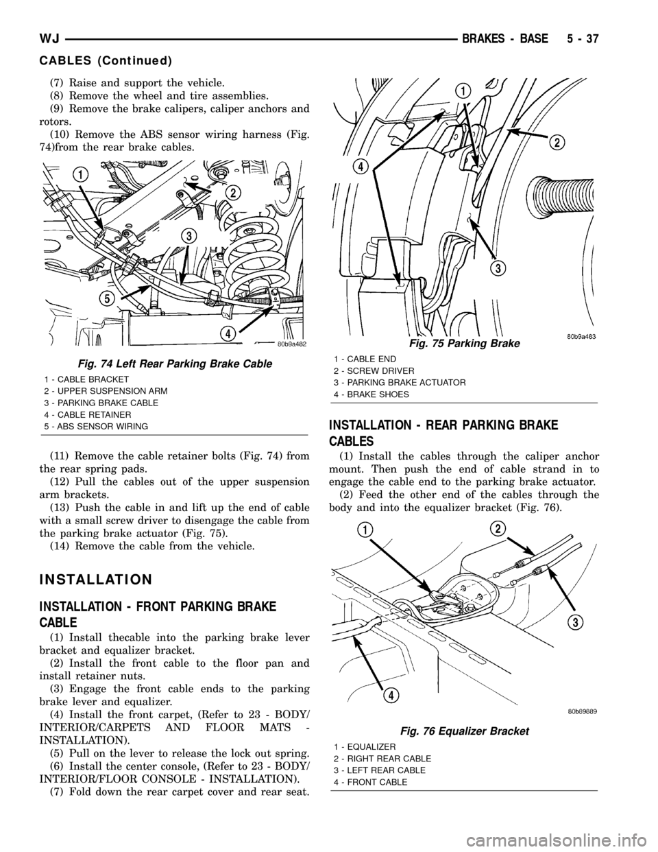
(10) Remove the ABS sensor wiring harness (Fig.
74)from the rear brake cables.
(11) Remove the cable retainer bolts (Fig. 74) from
the rear spring pads.
(12) Pull the cables out of the upper suspension
arm brackets.
(13) Push the cable in and lift up the end of cable
with a small screw driver to disengage the cable from
the parking brake actuator (Fig. 75).
(14) Remove the cable from the vehicle.
INSTALLATION
INSTALLATION - FRONT PARKING BRAKE
CABLE
(1) Install thecable into the parking brake lever
bracket and equalizer bracket.
(2) Install the front cable to the floor pan and
install retainer nuts.
(3) Engage the front cable ends to the parking
brake lever and equalizer.
(4) Install the front carpet, (Refer to 23 - BODY/
INTERIOR/CARPETS AND FLOOR MATS -
INSTALLATION).
(5) Pull on the lever to release the lock out spring.
(6) Install the center console, (Refer to 23 - BODY/
INTERIOR/FLOOR CONSOLE - INSTALLATION).
(7) Fold down the rear carpet cover and rear seat.
INSTALLATION - REAR PARKING BRAKE
CABLES
(1) Install the cables through the caliper anchor
mount. Then push the end of cable strand in to
engage the cable end to the parking brake actuator.
(2) Feed the other end of the cables through the
body and into the equalizer bracket (Fig. 76).
Fig. 74 Left Rear Parking Brake Cable
1 - CABLE BRACKET
2 - UPPER SUSPENSION ARM
3 - PARKING BRAKE CABLE
4 - CABLE RETAINER
5 - ABS SENSOR WIRING
Fig. 75 Parking Brake
1 - CABLE END
2 - SCREW DRIVER
3 - PARKING BRAKE ACTUATOR
4 - BRAKE SHOES
Fig. 76 Equalizer Bracket
1 - EQUALIZER
2 - RIGHT REAR CABLE
3 - LEFT REAR CABLE
4 - FRONT CABLE
WJBRAKES - BASE 5 - 37
CABLES (Continued)
Page 213 of 2199
(3) Push the cables into the upper suspension arm
brackets.
(4) Install the cable retainer bolts to the rear
spring pads.
(5) Install the ABS sensor wiring harness to the
rear brake cables.
(6) Install the rotors, caliper anchors and brake
calipers.
(7) Install the wheel and tire assemblies.
(8) Remove support and lower the vehicle.
(9) Engage the cable ends into the parking brake
equalizer.
(10) Pull on the lever to release the lock out
spring.
(11) Install center console, (Refer to 23 - BODY/IN-
TERIOR/FLOOR CONSOLE - INSTALLATION).
(12) Fold down the rear carpet cover and rear seat.
(13) Verify parking brake operation.
LEVER
REMOVAL
(1) Remove center console,(Refer to 23 - BODY/IN-
TERIOR/FLOOR CONSOLE - REMOVAL).
(2) Lift up rear seat and carpet covering the park-
ing brake cables.
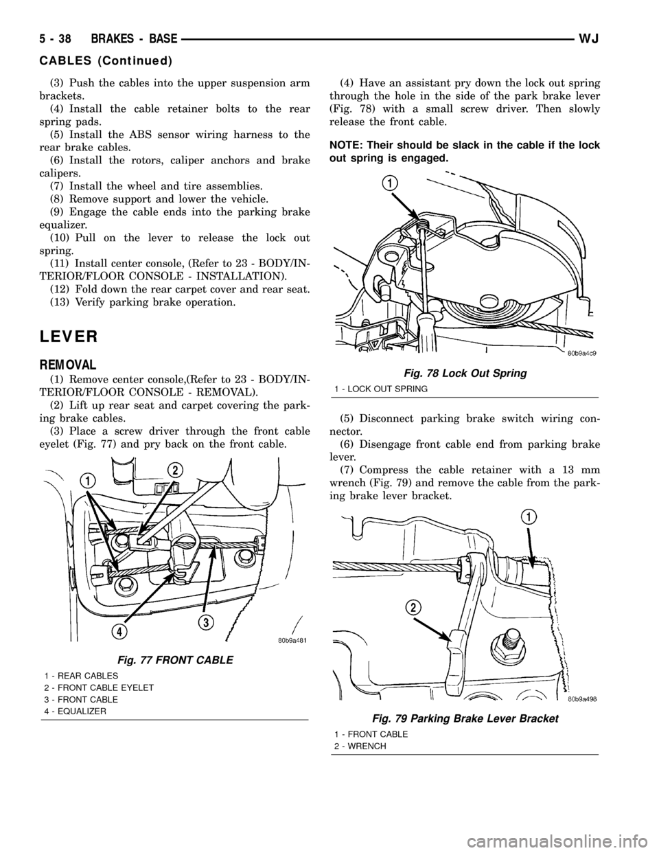
(3) Place a screw driver through the front cable
eyelet (Fig. 77) and pry back on the front cable.(4) Have an assistant pry down the lock out spring
through the hole in the side of the park brake lever
(Fig. 78) with a small screw driver. Then slowly
release the front cable.
NOTE: Their should be slack in the cable if the lock
out spring is engaged.
(5) Disconnect parking brake switch wiring con-
nector.
(6) Disengage front cable end from parking brake
lever.
(7) Compress the cable retainer with a 13 mm
wrench (Fig. 79) and remove the cable from the park-
ing brake lever bracket.
Fig. 77 FRONT CABLE
1 - REAR CABLES
2 - FRONT CABLE EYELET
3 - FRONT CABLE
4 - EQUALIZER
Fig. 78 Lock Out Spring
1 - LOCK OUT SPRING
Fig. 79 Parking Brake Lever Bracket
1 - FRONT CABLE
2 - WRENCH
5 - 38 BRAKES - BASEWJ
CABLES (Continued)
Page 219 of 2199
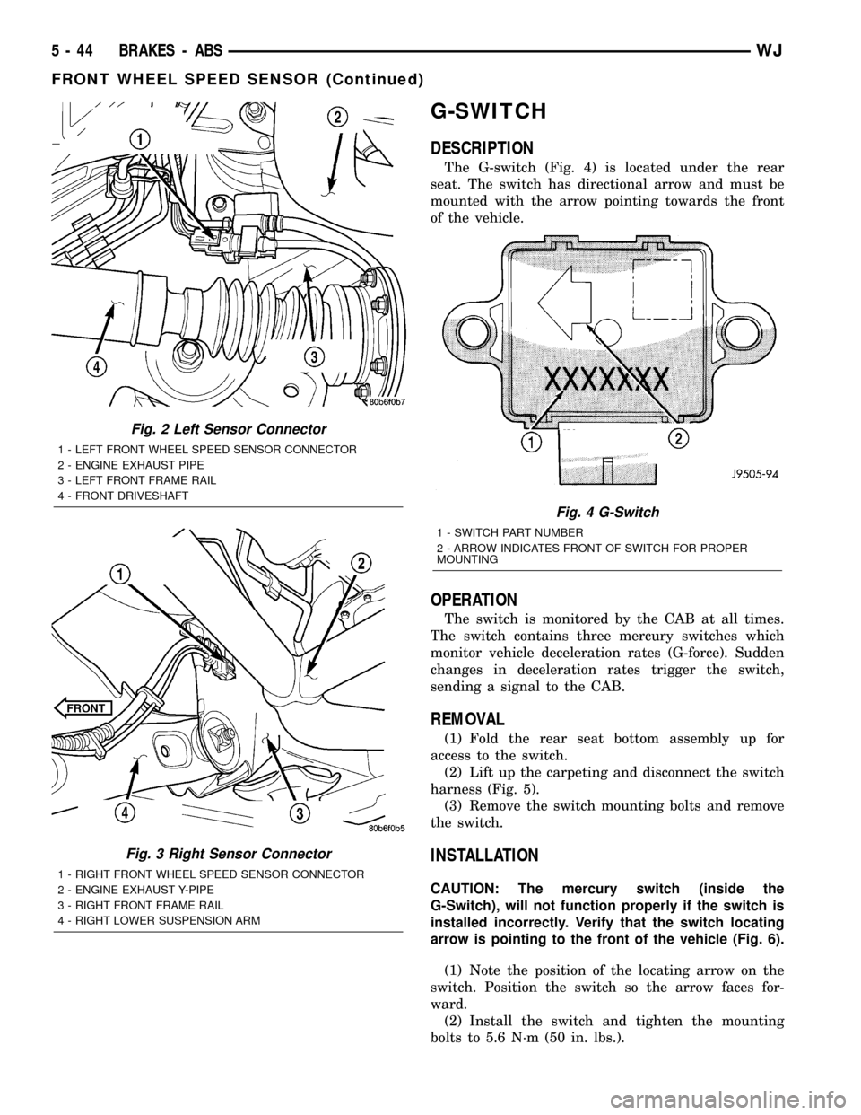
G-SWITCH
DESCRIPTION
The G-switch (Fig. 4) is located under the rear
seat. The switch has directional arrow and must be
mounted with the arrow pointing towards the front
of the vehicle.
OPERATION
The switch is monitored by the CAB at all times.
The switch contains three mercury switches which
monitor vehicle deceleration rates (G-force). Sudden
changes in deceleration rates trigger the switch,
sending a signal to the CAB.
REMOVAL
(1) Fold the rear seat bottom assembly up for
access to the switch.
(2) Lift up the carpeting and disconnect the switch
harness (Fig. 5).
(3) Remove the switch mounting bolts and remove
the switch.
INSTALLATION
CAUTION: The mercury switch (inside the
G-Switch), will not function properly if the switch is
installed incorrectly. Verify that the switch locating
arrow is pointing to the front of the vehicle (Fig. 6).
(1) Note the position of the locating arrow on the
switch. Position the switch so the arrow faces for-
ward.
(2) Install the switch and tighten the mounting
bolts to 5.6 N´m (50 in. lbs.).
Fig. 2 Left Sensor Connector
1 - LEFT FRONT WHEEL SPEED SENSOR CONNECTOR
2 - ENGINE EXHAUST PIPE
3 - LEFT FRONT FRAME RAIL
4 - FRONT DRIVESHAFT
Fig. 3 Right Sensor Connector
1 - RIGHT FRONT WHEEL SPEED SENSOR CONNECTOR
2 - ENGINE EXHAUST Y-PIPE
3 - RIGHT FRONT FRAME RAIL
4 - RIGHT LOWER SUSPENSION ARM
Fig. 4 G-Switch
1 - SWITCH PART NUMBER
2 - ARROW INDICATES FRONT OF SWITCH FOR PROPER
MOUNTING
5 - 44 BRAKES - ABSWJ
FRONT WHEEL SPEED SENSOR (Continued)
Page 392 of 2199
CONDITION POSSIBLE CAUSES CORRECTION
HORN SOUNDS
CONTINUOUSLY1. Faulty horn relay. 1. Refer to Horn Relay for the proper horn relay
diagnosis and testing procedures. Replace the
horn relay or repair the shorted horn relay control
circuit, if required.
2. Faulty horn switch. 2. Refer to Horn Switch for the proper horn switch
diagnosis and testing procedures. Replace the
horn switch or repair the shorted horn switch
circuit, if required.
HORN
DESCRIPTION
The dual electromagnetic diaphragm-type horns
are standard equipment on this model. Both horns
are secured to a mounting bracket. The mounting
bracket is secured with a screw to the back side of
the right extension of the radiator closure assembly,
just ahead of the right front wheel house and below
the front wheel house extension. The two horns are
connected in parallel. Each horn is grounded through
its wire harness connector and circuit to an eyelet
secured to the right inner fender shield near the bat-
tery, and receives battery feed through the closed
contacts of the horn relay.
The horns cannot be repaired or adjusted and, if
faulty or damaged, they must be individually
replaced.
OPERATION
Within the two halves of the molded plastic horn
housing are a flexible diaphragm, a plunger, an elec-
tromagnetic coil and a set of contact points. The dia-
phragm is secured in suspension around its
perimeter by the mating surfaces of the horn hous-
ing. The plunger is secured to the center of the dia-
phragm and extends into the center of the
electromagnet. The contact points control the current
flow through the electromagnet.
When the horn is energized, electrical current
flows through the closed contact points to the electro-
magnet. The resulting electromagnetic field draws
the plunger and diaphragm toward it until that
movement mechanically opens the contact points.
When the contact points open, the electromagnetic
field collapses allowing the plunger and diaphragm to
return to their relaxed positions and closing the con-
tact points again. This cycle continues repeating at a
very rapid rate producing the vibration and move-
ment of air that creates the sound that is directed
through the horn outlet.
DIAGNOSIS AND TESTING - HORN
Refer to the appropriate wiring information. The
wiring information includes wiring diagrams, proper
wire and connector repair procedures, details of wire
harness routing and retention, connector pin-out
information and location views for the various wire
harness connectors, splices and grounds.
(1) Disconnect the wire harness connector(s) from
the horn connector receptacle(s). Measure the resis-
tance between the ground circuit cavity of the horn(s)
wire harness connector(s) and a good ground. There
should be no measurable resistance. If OK, go to Step
2. If not OK, repair the open ground circuit to ground
as required.
(2) Check for battery voltage at the horn relay out-
put circuit cavity of the horn(s) wire harness connec-
tor(s). There should be zero volts. If OK, go to Step 3.
If not OK, repair the shorted horn relay output cir-
cuit or replace the faulty horn relay as required.
(3) Depress the horn switch. There should now be
battery voltage at the horn relay output circuit cavity
of the horn(s) wire harness connector(s). If OK,
replace the faulty horns. If not OK, repair the open
horn relay output circuit to the horn relay as
required.
REMOVAL
(1) Disconnect and isolate the battery negative
cable.
(2) Raise and support the vehicle.
(3) Remove the lower front half of the inner liner
from the right front fender wheel house. (Refer to 23
- BODY/EXTERIOR/FRONT FENDER - REMOVAL).
(4) Reach through the front of the right front
fender wheel house opening to access and disconnect
the two right headlamp and dash wire harness con-
nectors from the horn connector receptacles (Fig. 1).
Be certain to disengage the connector lock tabs
before disconnecting them from the horn connector
receptacles.
(5) Remove the screw that secures the horn
mounting bracket to the right extension of the radi-
ator closure assembly.
WJHORN 8H - 3
HORN SYSTEM (Continued)
Page 468 of 2199

(from rear of vehicle forward) to verify accuracy of
the line placement.
(4) Rock vehicle side-to-side three times to allow
suspension to stabilize.
(5) Jounce front suspension three times by pushing
downward on front bumper and releasing.
(6) Measure the distance from the center of head-
lamp lens to the floor. Transfer measurement to the
alignment screen (with tape). Use this line for
up/down adjustment reference.
(7) Measure distance from the centerline of the
vehicle to the center of each headlamp being aligned.
Transfer measurements to screen (with tape) to each
side of vehicle centerline. Use these lines for left/
right adjustment reference.
HEADLAMP ADJUSTMENT
A properly aimed low beam will project the top
edge of the beam intensity pattern on the screen
from 25 mm (1 in.) above to 75 mm (3 in.) below
headlamp centerline. The side-to-side left edge of the
beam intensity pattern should be from 50 mm (2 in.)
left to 50 mm (2 in.) right of headlamp centerline
(Fig. 17).
(1) Clean front of the headlamps.
(2) Place headlamps on LOW beam.(3) Cover front of the headlamp that is not being
adjusted.
(4) Turn adjustment screw (Fig. 18) and (Fig. 19)
until the top edge of the beam intensity pattern is
positioned within 25 mm (1 in.) above or 75 mm (3
in.) below the headlamp horizontal centerline.
(5) Cover front of the headlamp and adjust the
other headlamp beam as instructed below.
(6) Rotate the adjustment screw until the top edge
of the beam intensity pattern is positioned within 25
mm (1 in.) above or 75 mm (3 in.) below the head-
lamp horizontal centerline.
LICENSE PLATE LAMP
REMOVAL
REMOVAL - BULB
(1) Remove lamp assembly from liftgate lamp mod-
ule.
(2) Rotate bulb socket counterclockwise to discon-
nect bulb socket from lamp.
(3) Remove bulb from socket.
Fig. 16 Headlamp Alignment ScreenÐTypical
1 - CENTER OF VEHICLE TO CENTER OF HEADLAMP LENS
2 - FLOOR TO CENTER OF HEADLAMP LENS
3 - 7.62 METERS (25 FEET)4 - FRONT OF HEADLAMP
5 - VEHICLE CENTERLINE
WJLAMPS/LIGHTING - EXTERIOR 8L - 17
HEADLAMP UNIT (Continued)
Page 635 of 2199
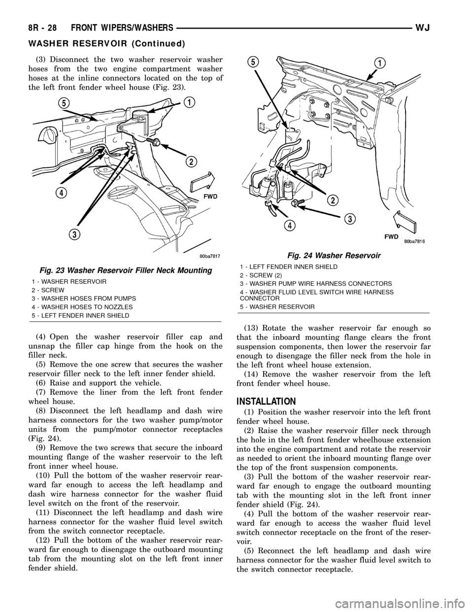
(3) Disconnect the two washer reservoir washer
hoses from the two engine compartment washer
hoses at the inline connectors located on the top of
the left front fender wheel house (Fig. 23).
(4) Open the washer reservoir filler cap and
unsnap the filler cap hinge from the hook on the
filler neck.
(5) Remove the one screw that secures the washer
reservoir filler neck to the left inner fender shield.
(6) Raise and support the vehicle.
(7) Remove the liner from the left front fender
wheel house.
(8) Disconnect the left headlamp and dash wire
harness connectors for the two washer pump/motor
units from the pump/motor connector receptacles
(Fig. 24).
(9) Remove the two screws that secure the inboard
mounting flange of the washer reservoir to the left
front inner wheel house.
(10) Pull the bottom of the washer reservoir rear-
ward far enough to access the left headlamp and
dash wire harness connector for the washer fluid
level switch on the front of the reservoir.
(11) Disconnect the left headlamp and dash wire
harness connector for the washer fluid level switch
from the switch connector receptacle.
(12) Pull the bottom of the washer reservoir rear-
ward far enough to disengage the outboard mounting
tab from the mounting slot on the left front inner
fender shield.(13) Rotate the washer reservoir far enough so
that the inboard mounting flange clears the front
suspension components, then lower the reservoir far
enough to disengage the filler neck from the hole in
the left front wheel house extension.
(14) Remove the washer reservoir from the left
front fender wheel house.
INSTALLATION
(1) Position the washer reservoir into the left front
fender wheel house.
(2) Raise the washer reservoir filler neck through
the hole in the left front fender wheelhouse extension
into the engine compartment and rotate the reservoir
as needed to orient the inboard mounting flange over
the top of the front suspension components.
(3) Pull the bottom of the washer reservoir rear-
ward far enough to engage the outboard mounting
tab with the mounting slot in the left front inner
fender shield (Fig. 24).
(4) Pull the bottom of the washer reservoir rear-
ward far enough to access the washer fluid level
switch connector receptacle on the front of the reser-
voir.
(5) Reconnect the left headlamp and dash wire
harness connector for the washer fluid level switch to
the switch connector receptacle.
Fig. 23 Washer Reservoir Filler Neck Mounting
1 - WASHER RESERVOIR
2 - SCREW
3 - WASHER HOSES FROM PUMPS
4 - WASHER HOSES TO NOZZLES
5 - LEFT FENDER INNER SHIELD
Fig. 24 Washer Reservoir
1 - LEFT FENDER INNER SHIELD
2 - SCREW (2)
3 - WASHER PUMP WIRE HARNESS CONNECTORS
4 - WASHER FLUID LEVEL SWITCH WIRE HARNESS
CONNECTOR
5 - WASHER RESERVOIR
8R - 28 FRONT WIPERS/WASHERSWJ
WASHER RESERVOIR (Continued)
Page 661 of 2199
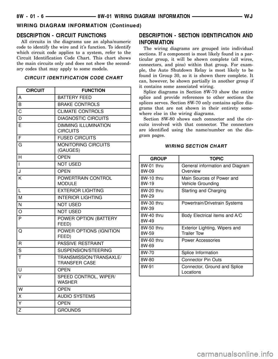
DESCRIPTION - CIRCUIT FUNCTIONS
All circuits in the diagrams use an alpha/numeric
code to identify the wire and it's function. To identify
which circuit code applies to a system, refer to the
Circuit Identification Code Chart. This chart shows
the main circuits only and does not show the second-
ary codes that may apply to some models.
CIRCUIT IDENTIFICATION CODE CHART
CIRCUIT FUNCTION
A BATTERY FEED
B BRAKE CONTROLS
C CLIMATE CONTROLS
D DIAGNOSTIC CIRCUITS
E DIMMING ILLUMINATION
CIRCUITS
F FUSED CIRCUITS
G MONITORING CIRCUITS
(GAUGES)
H OPEN
I NOT USED
J OPEN
K POWERTRAIN CONTROL
MODULE
L EXTERIOR LIGHTING
M INTERIOR LIGHTING
N NOT USED
O NOT USED
P POWER OPTION (BATTERY
FEED)
Q POWER OPTIONS (IGNITION
FEED)
R PASSIVE RESTRAINT
S SUSPENSION/STEERING
T TRANSMISSION/TRANSAXLE/
TRANSFER CASE
U OPEN
V SPEED CONTROL, WIPER/
WASHER
W OPEN
X AUDIO SYSTEMS
Y OPEN
Z GROUNDS
DESCRIPTION - SECTION IDENTIFICATION AND
INFORMATION
The wiring diagrams are grouped into individual
sections. If a component is most likely found in a par-
ticular group, it will be shown complete (all wires,
connectors, and pins) within that group. For exam-
ple, the Auto Shutdown Relay is most likely to be
found in Group 30, so it is shown there complete. It
can, however, be shown partially in another group if
it contains some associated wiring.
Splice diagrams in Section 8W-70 show the entire
splice and provide references to other sections the
splices serves. Section 8W-70 only contains splice dia-
grams that are not shown in their entirety some-
where else in the wiring diagrams.
Section 8W-80 shows each connector and the cir-
cuits involved with that connector. The connectors
are identified using the name/number on the dia-
gram pages.
WIRING SECTION CHART
GROUP TOPIC
8W-01 thru
8W-09General information and Diagram
Overview
8W-10 thru
8W-19Main Sources of Power and
Vehicle Grounding
8W-20 thru
8W-29Starting and Charging
8W-30 thru
8W-39Powertrain/Drivetrain Systems
8W-40 thru
8W-49Body Electrical items and A/C
8W-50 thru
8W-59Exterior Lighting, Wipers and
Trailer Tow
8W-60 thru
8W-69Power Accessories
8W-70 Splice Information
8W-80 Connector Pin Outs
8W-91 Connector, Ground and Splice
Locations
8W - 01 - 6 8W-01 WIRING DIAGRAM INFORMATIONWJ
WIRING DIAGRAM INFORMATION (Continued)
Page 1479 of 2199
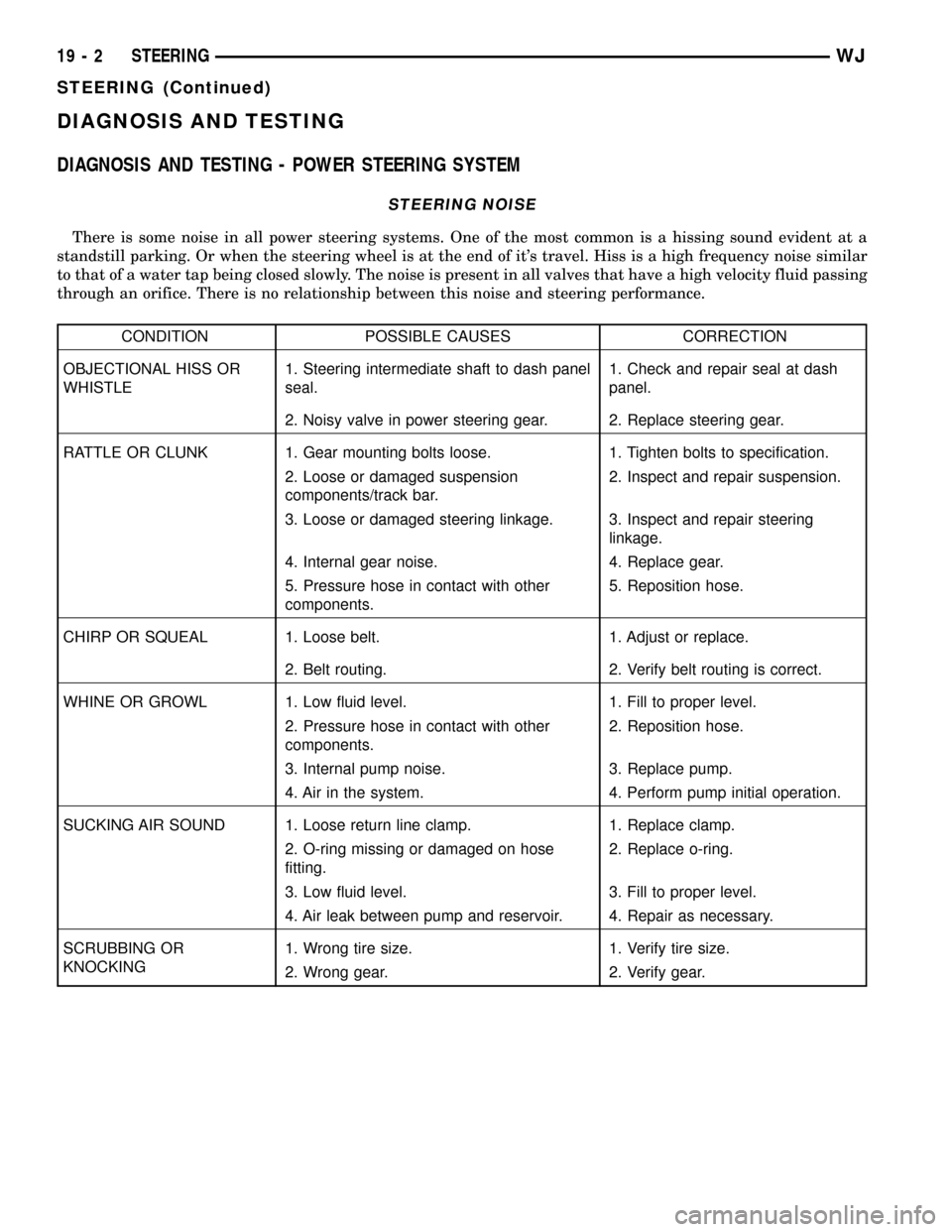
DIAGNOSIS AND TESTING
DIAGNOSIS AND TESTING - POWER STEERING SYSTEM
STEERING NOISE
There is some noise in all power steering systems. One of the most common is a hissing sound evident at a
standstill parking. Or when the steering wheel is at the end of it's travel. Hiss is a high frequency noise similar
to that of a water tap being closed slowly. The noise is present in all valves that have a high velocity fluid passing
through an orifice. There is no relationship between this noise and steering performance.
CONDITION POSSIBLE CAUSES CORRECTION
OBJECTIONAL HISS OR
WHISTLE1. Steering intermediate shaft to dash panel
seal.1. Check and repair seal at dash
panel.
2. Noisy valve in power steering gear. 2. Replace steering gear.
RATTLE OR CLUNK 1. Gear mounting bolts loose. 1. Tighten bolts to specification.
2. Loose or damaged suspension
components/track bar.2. Inspect and repair suspension.
3. Loose or damaged steering linkage. 3. Inspect and repair steering
linkage.
4. Internal gear noise. 4. Replace gear.
5. Pressure hose in contact with other
components.5. Reposition hose.
CHIRP OR SQUEAL 1. Loose belt. 1. Adjust or replace.
2. Belt routing. 2. Verify belt routing is correct.
WHINE OR GROWL 1. Low fluid level. 1. Fill to proper level.
2. Pressure hose in contact with other
components.2. Reposition hose.
3. Internal pump noise. 3. Replace pump.
4. Air in the system. 4. Perform pump initial operation.
SUCKING AIR SOUND 1. Loose return line clamp. 1. Replace clamp.
2. O-ring missing or damaged on hose
fitting.2. Replace o-ring.
3. Low fluid level. 3. Fill to proper level.
4. Air leak between pump and reservoir. 4. Repair as necessary.
SCRUBBING OR
KNOCKING1. Wrong tire size. 1. Verify tire size.
2. Wrong gear. 2. Verify gear.
19 - 2 STEERINGWJ
STEERING (Continued)