drain bolt JEEP GRAND CHEROKEE 2003 WJ / 2.G Owner's Guide
[x] Cancel search | Manufacturer: JEEP, Model Year: 2003, Model line: GRAND CHEROKEE, Model: JEEP GRAND CHEROKEE 2003 WJ / 2.GPages: 2199, PDF Size: 76.01 MB
Page 1323 of 2199
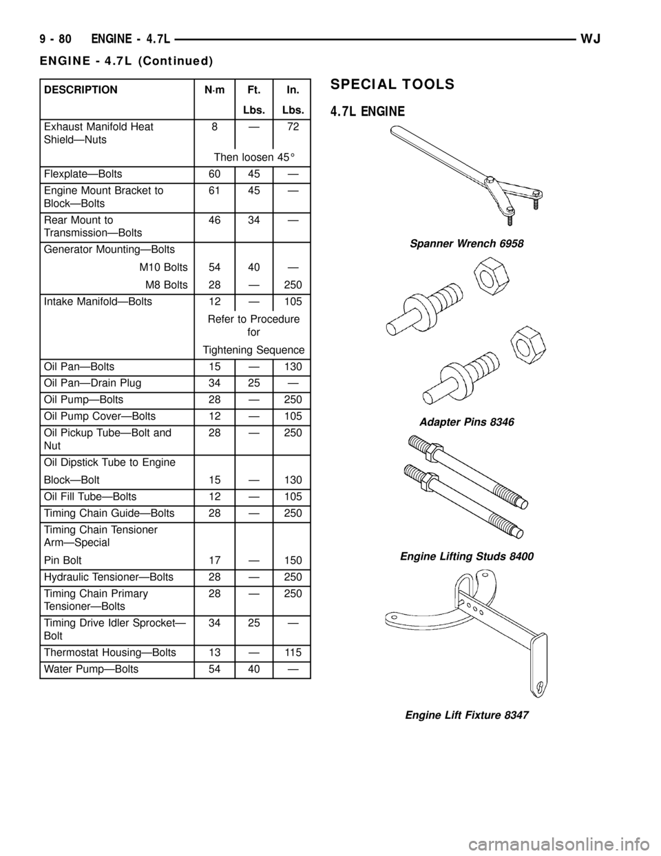
DESCRIPTION N´m Ft. In.
Lbs. Lbs.
Exhaust Manifold Heat
ShieldÐNuts8Ð72
Then loosen 45É
FlexplateÐBolts 60 45 Ð
Engine Mount Bracket to
BlockÐBolts61 45 Ð
Rear Mount to
TransmissionÐBolts46 34 Ð
Generator MountingÐBolts
M10 Bolts 54 40 Ð
M8 Bolts 28 Ð 250
Intake ManifoldÐBolts 12 Ð 105
Refer to Procedure
for
Tightening Sequence
Oil PanÐBolts 15 Ð 130
Oil PanÐDrain Plug 34 25 Ð
Oil PumpÐBolts 28 Ð 250
Oil Pump CoverÐBolts 12 Ð 105
Oil Pickup TubeÐBolt and
Nut28 Ð 250
Oil Dipstick Tube to Engine
BlockÐBolt 15 Ð 130
Oil Fill TubeÐBolts 12 Ð 105
Timing Chain GuideÐBolts 28 Ð 250
Timing Chain Tensioner
ArmÐSpecial
Pin Bolt 17 Ð 150
Hydraulic TensionerÐBolts 28 Ð 250
Timing Chain Primary
TensionerÐBolts28 Ð 250
Timing Drive Idler SprocketÐ
Bolt34 25 Ð
Thermostat HousingÐBolts 13 Ð 115
Water PumpÐBolts 54 40 ÐSPECIAL TOOLS
4.7L ENGINE
Spanner Wrench 6958
Adapter Pins 8346
Engine Lifting Studs 8400
Engine Lift Fixture 8347
9 - 80 ENGINE - 4.7LWJ
ENGINE - 4.7L (Continued)
Page 1327 of 2199
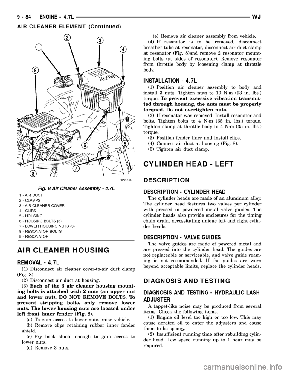
AIR CLEANER HOUSING
REMOVAL - 4.7L
(1) Disconnect air cleaner cover-to-air duct clamp
(Fig. 8).
(2) Disconnect air duct at housing.
(3)Each of the 3 air cleaner housing mount-
ing bolts is attached with 2 nuts (an upper nut
and lower nut). DO NOT REMOVE BOLTS. To
prevent stripping bolts, only remove lower
nuts. The lower housing nuts are located under
left front inner fender (Fig. 8).
(a) To gain access to lower nuts, raise vehicle.
(b) Remove clips retaining rubber inner fender
shield.
(c) Pry back shield enough to gain access to
lower nuts.
(d) Remove 3 nuts.(e) Remove air cleaner assembly from vehicle.
(4) If resonator is to be removed, disconnect
breather tube at resonator, disconnect air duct clamp
at resonator (Fig. 8)and remove 2 resonator mount-
ing bolts (at sides of resonator). Remove resonator
from throttle body by loosening clamp at throttle
body.
INSTALLATION - 4.7L
(1) Position air cleaner assembly to body and
install 3 nuts. Tighten nuts to 10 N´m (93 in. lbs.)
torque.To prevent excessive vibration transmit-
ted through housing, the nuts must be properly
torqued. Do not overtighten nuts.
(2) If resonator was removed: Install resonator and
bolts. Tighten bolts to 4 N´m (35 in. lbs.) torque.
Tighten clamp at throttle body to 4 N´m (35 in. lbs.)
torque.
(3) Position fender liner and install clips.
(4) Connect air duct at housing (Fig. 8).
(5) Tighten air duct clamp.
CYLINDER HEAD - LEFT
DESCRIPTION
DESCRIPTION - CYLINDER HEAD
The cylinder heads are made of an aluminum alloy.
The cylinder head features two valves per cylinder
with pressed in powdered metal valve guides. The
cylinder heads also provide enclosures for the timing
chain drain, necessitating unique left and right cylin-
der heads.
DESCRIPTION - VALVE GUIDES
The valve guides are made of powered metal and
are pressed into the cylinder head. The guides are
not replaceable or serviceable, and valve guide ream-
ing is not recommended. If the guides are worn
beyond acceptable limits, replace the cylinder heads.
DIAGNOSIS AND TESTING
DIAGNOSIS AND TESTING - HYDRAULIC LASH
ADJUSTER
A tappet-like noise may be produced from several
items. Check the following items.
(1) Engine oil level too high or too low. This may
cause aerated oil to enter the adjusters and cause
them to be spongy.
(2) Insufficient running time after rebuilding cylin-
der head. Low speed running up to 1 hour may be
required.
Fig. 8 Air Cleaner Assembly - 4.7L
1 - AIR DUCT
2 - CLAMPS
3 - AIR CLEANER COVER
4 - CLIPS
5 - HOUSING
6 - HOUSING BOLTS (3)
7 - LOWER HOUSING NUTS (3)
8 - RESONATOR BOLTS
9 - RESONATOR
9 - 84 ENGINE - 4.7LWJ
AIR CLEANER ELEMENT (Continued)
Page 1347 of 2199
CYLINDER HEAD COVER(S) -
RIGHT
DESCRIPTION
The cylinder head covers are made of die cast mag-
nesium, and are not interchangeable from side-to-
side. It is imperative that nothing rest on the
cylinder head covers. Prolonged contact with other
items may wear a hole in the cylinder head cover.
REMOVAL - RIGHT SIDE
(1) Disconnect battery negative cable.
(2) Remove air cleaner assembly, resonator assem-
bly and air inlet hose.
(3) Drain cooling system (Refer to 7 - COOLING -
STANDARD PROCEDURE).
(4) Remove accessory drive belt (Refer to 7 -
COOLING/ACCESSORY DRIVE/DRIVE BELTS -
REMOVAL).
(5) Remove air conditioning compressor retaining
bolts and move compressor to the left.
(6) Remove heater hoses.
(7) Disconnect injector and ignition coil connectors.
(8) Disconnect and remove positive crankcase ven-
tilation (PCV) hose.
(9) Remove oil fill tube.
(10) Un-clip injector and ignition coil harness and
move away from cylinder head cover.
(11) Remove right rear breather tube and filter
assembly.
(12) Remove cylinder head cover retaining bolts.
(13) Remove cylinder head cover.
NOTE: The gasket may be used again, provided no
cuts, tears, or deformation has occurred.
CLEANING
Clean cylinder head cover gasket surface.
Clean head rail, if necessary.
INSTALLATION - RIGHT SIDE
CAUTION: Do not use harsh cleaners to clean the
cylinder head covers. Severe damage to covers
may occur.
CAUTION: DO NOT allow other components includ-
ing the wire harness to rest on or against the
engine cylinder head cover. Prolonged contact with
other objects may wear a hole in the cylinder head
cover.
(1) Clean cylinder head cover and both sealing sur-
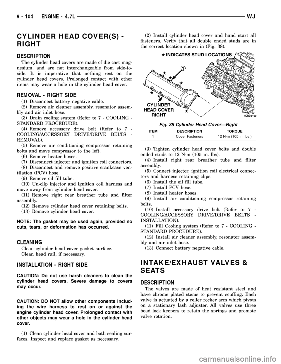
faces. Inspect and replace gasket as necessary.(2) Install cylinder head cover and hand start all
fasteners. Verify that all double ended studs are in
the correct location shown in (Fig. 38).
(3) Tighten cylinder head cover bolts and double
ended studs to 12 N´m (105 in. lbs).
(4) Install right rear breather tube and filter
assembly.
(5) Connect injector, ignition coil electrical connec-
tors and harness retaining clips.
(6) Install the oil fill tube.
(7) Install PCV hose.
(8) Install heater hoses.
(9) Install air conditioning compressor retaining
bolts.
(10) Install accessory drive belt (Refer to 7 -
COOLING/ACCESSORY DRIVE/DRIVE BELTS -
INSTALLATION).
(11) Fill Cooling system (Refer to 7 - COOLING -
STANDARD PROCEDURE).
(12) Install air cleaner assembly, resonator assem-
bly and air inlet hose.
(13) Connect battery negative cable.
INTAKE/EXHAUST VALVES &
SEATS
DESCRIPTION
The valves are made of heat resistant steel and
have chrome plated stems to prevent scuffing. Each
valve is actuated by a roller rocker arm which pivots
on a stationary lash adjuster. All valves use three
bead lock keepers to retain the springs and promote
valve rotation.
Fig. 38 Cylinder Head CoverÐRight
ITEM DESCRIPTION TORQUE
1 Cover Fasteners 12 N´m (105 in. lbs.)
9 - 104 ENGINE - 4.7LWJ
Page 1375 of 2199
(5) With a wiping cloth, clean the gasket sealing
surface of oil and grime.
INSTALLATION
(1) Lightly lubricate oil filter gasket with engine
oil.
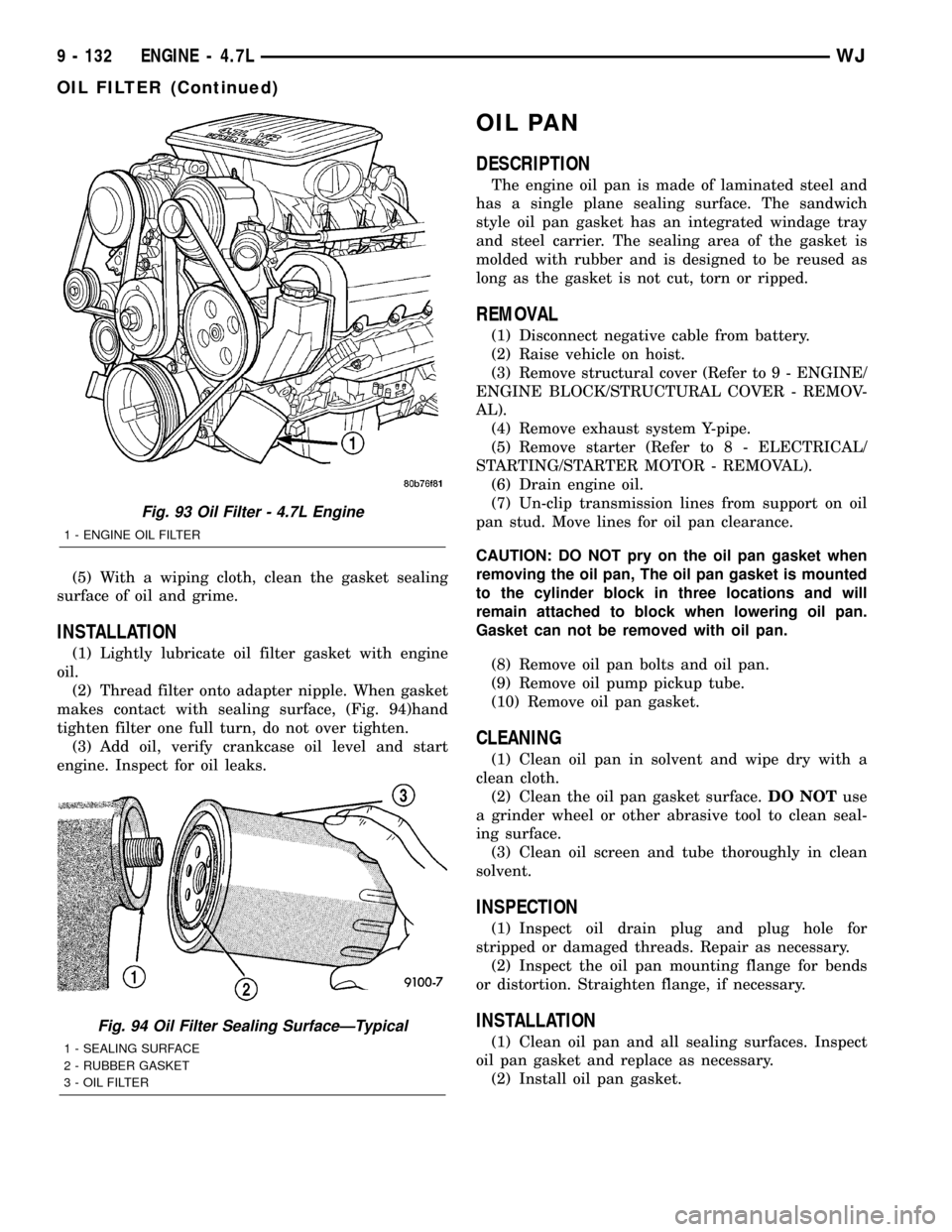
(2) Thread filter onto adapter nipple. When gasket
makes contact with sealing surface, (Fig. 94)hand
tighten filter one full turn, do not over tighten.
(3) Add oil, verify crankcase oil level and start
engine. Inspect for oil leaks.
OIL PAN
DESCRIPTION
The engine oil pan is made of laminated steel and
has a single plane sealing surface. The sandwich
style oil pan gasket has an integrated windage tray
and steel carrier. The sealing area of the gasket is
molded with rubber and is designed to be reused as
long as the gasket is not cut, torn or ripped.
REMOVAL
(1) Disconnect negative cable from battery.
(2) Raise vehicle on hoist.
(3) Remove structural cover (Refer to 9 - ENGINE/
ENGINE BLOCK/STRUCTURAL COVER - REMOV-
AL).
(4) Remove exhaust system Y-pipe.
(5) Remove starter (Refer to 8 - ELECTRICAL/
STARTING/STARTER MOTOR - REMOVAL).
(6) Drain engine oil.
(7) Un-clip transmission lines from support on oil
pan stud. Move lines for oil pan clearance.
CAUTION: DO NOT pry on the oil pan gasket when
removing the oil pan, The oil pan gasket is mounted
to the cylinder block in three locations and will
remain attached to block when lowering oil pan.
Gasket can not be removed with oil pan.
(8) Remove oil pan bolts and oil pan.
(9) Remove oil pump pickup tube.
(10) Remove oil pan gasket.
CLEANING
(1) Clean oil pan in solvent and wipe dry with a
clean cloth.
(2) Clean the oil pan gasket surface.DO NOTuse
a grinder wheel or other abrasive tool to clean seal-
ing surface.
(3) Clean oil screen and tube thoroughly in clean
solvent.
INSPECTION
(1) Inspect oil drain plug and plug hole for
stripped or damaged threads. Repair as necessary.
(2) Inspect the oil pan mounting flange for bends
or distortion. Straighten flange, if necessary.
INSTALLATION
(1) Clean oil pan and all sealing surfaces. Inspect
oil pan gasket and replace as necessary.
(2) Install oil pan gasket.
Fig. 93 Oil Filter - 4.7L Engine
1 - ENGINE OIL FILTER
Fig. 94 Oil Filter Sealing SurfaceÐTypical
1 - SEALING SURFACE
2 - RUBBER GASKET
3 - OIL FILTER
9 - 132 ENGINE - 4.7LWJ
OIL FILTER (Continued)
Page 1380 of 2199
(6) Remove accessory drive belt (Refer to 7 -
COOLING/ACCESSORY DRIVE/DRIVE BELTS -
REMOVAL).
(7) Disconnect generator electrical connections.
(8) Unbolt the generator and move it away from
the intake manifold for clearance.
(9) Disconnect air conditioning compressor electri-
cal connections.
(10) Unbolt the air conditioning compressor and
move it away from the intake manifold for clearance.
(11) Disconnect left and right radio suppressor
straps.
(12) Disconnect and remove ignition coil towers
(Refer to 8 - ELECTRICAL/IGNITION CONTROL/
IGNITION COIL - REMOVAL).
(13) Remove top oil dipstick tube retaining bolt
and ground strap.
(14) Bleed pressure from fuel system (Refer to 14 -
FUEL SYSTEM/FUEL DELIVERY - STANDARD
PROCEDURE).
(15) Remove fuel rail (Refer to 14 - FUEL SYS-
TEM/FUEL DELIVERY/FUEL RAIL - REMOVAL).
(16) Remove throttle body assembly and mounting
bracket.
(17) Drain cooling system below coolant tempera-
ture level (Refer to 7 - COOLING - STANDARD
PROCEDURE).
(18) Remove coolant temperature sensor (Refer to
7 - COOLING/ENGINE/ENGINE COOLANT TEMP
SENSOR - REMOVAL).
(19) Remove cowl to hood seal. (Refer to 23 -
BODY/WEATHERSTRIP/SEALS/COWL WEATHER-
STRIP - REMOVAL).
(20) Remove right side engine lifting stud.
(21) Remove intake manifold retaining fasteners,
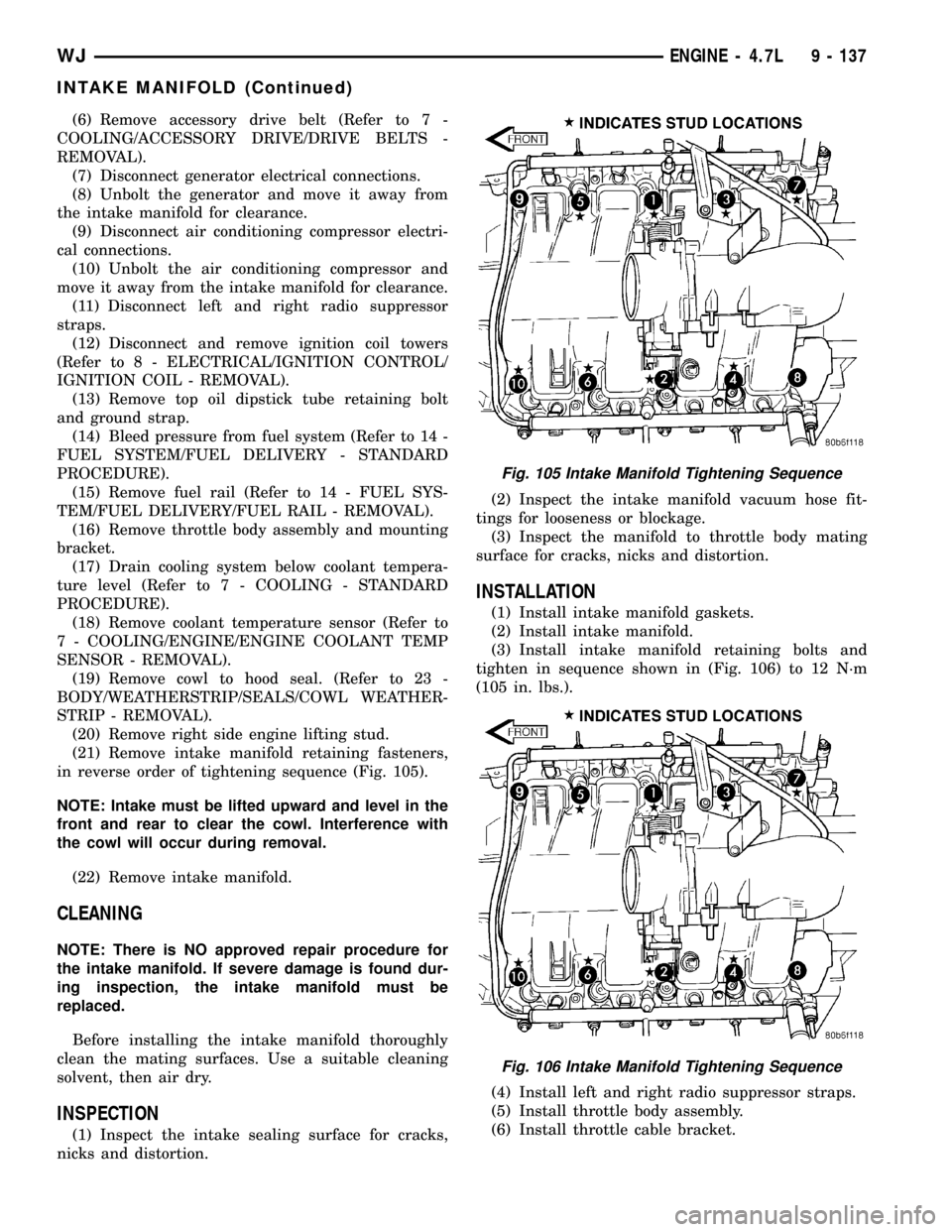
in reverse order of tightening sequence (Fig. 105).
NOTE: Intake must be lifted upward and level in the
front and rear to clear the cowl. Interference with
the cowl will occur during removal.
(22) Remove intake manifold.
CLEANING
NOTE: There is NO approved repair procedure for
the intake manifold. If severe damage is found dur-
ing inspection, the intake manifold must be
replaced.
Before installing the intake manifold thoroughly
clean the mating surfaces. Use a suitable cleaning
solvent, then air dry.
INSPECTION
(1) Inspect the intake sealing surface for cracks,
nicks and distortion.(2) Inspect the intake manifold vacuum hose fit-
tings for looseness or blockage.
(3) Inspect the manifold to throttle body mating
surface for cracks, nicks and distortion.
INSTALLATION
(1) Install intake manifold gaskets.
(2) Install intake manifold.
(3) Install intake manifold retaining bolts and
tighten in sequence shown in (Fig. 106) to 12 N´m
(105 in. lbs.).
(4) Install left and right radio suppressor straps.
(5) Install throttle body assembly.
(6) Install throttle cable bracket.
Fig. 105 Intake Manifold Tightening Sequence
Fig. 106 Intake Manifold Tightening Sequence
WJENGINE - 4.7L 9 - 137
INTAKE MANIFOLD (Continued)
Page 1383 of 2199
(7) Remove A/C compressor from mounting and set
aside.
(8) Remove A/C accumulator support bracket fas-
tener.
(9) Drain coolant (Refer to 7 - COOLING - STAN-
DARD PROCEDURE).
(10) Remove heater hoses at engine.
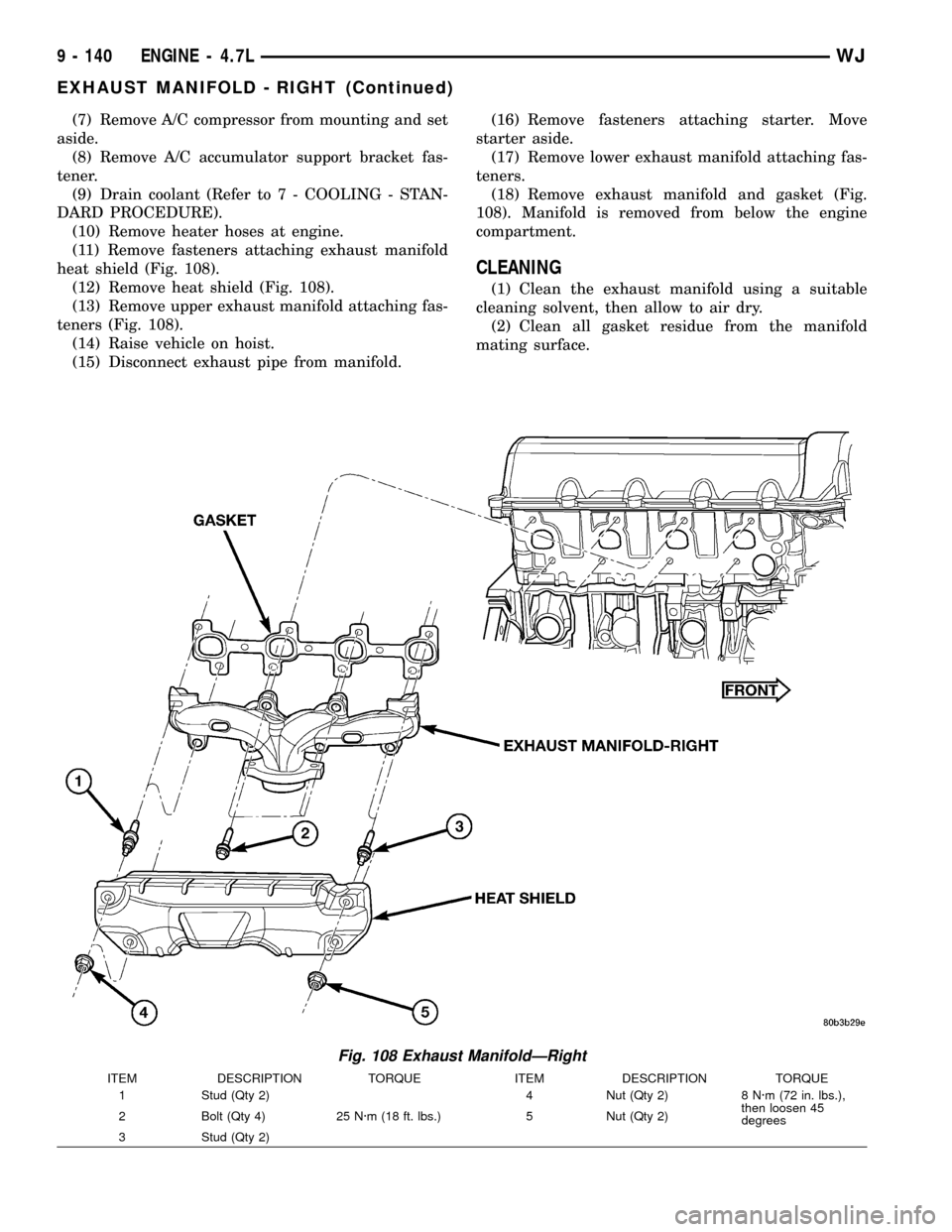
(11) Remove fasteners attaching exhaust manifold
heat shield (Fig. 108).
(12) Remove heat shield (Fig. 108).
(13) Remove upper exhaust manifold attaching fas-
teners (Fig. 108).
(14) Raise vehicle on hoist.
(15) Disconnect exhaust pipe from manifold.(16) Remove fasteners attaching starter. Move
starter aside.
(17) Remove lower exhaust manifold attaching fas-
teners.
(18) Remove exhaust manifold and gasket (Fig.
108). Manifold is removed from below the engine
compartment.
CLEANING
(1) Clean the exhaust manifold using a suitable
cleaning solvent, then allow to air dry.
(2) Clean all gasket residue from the manifold
mating surface.
Fig. 108 Exhaust ManifoldÐRight
ITEM DESCRIPTION TORQUE ITEM DESCRIPTION TORQUE
1 Stud (Qty 2)
25 N´m (18 ft. lbs.)4 Nut (Qty 2) 8 N´m (72 in. lbs.),
then loosen 45
degrees 2 Bolt (Qty 4) 5 Nut (Qty 2)
3 Stud (Qty 2)
9 - 140 ENGINE - 4.7LWJ
EXHAUST MANIFOLD - RIGHT (Continued)
Page 1390 of 2199
TIMING BELT/CHAIN AND
SPROCKETS
REMOVAL
(1) Disconnect negative cable from battery.
(2) Drain cooling system (Refer to 7 - COOLING -
STANDARD PROCEDURE).
(3) Remove right and left cylinder head covers
(Refer to 9 - ENGINE/CYLINDER HEAD/CYLIN-
DER HEAD COVER(S) - REMOVAL).
(4) Remove radiator fan (Refer to 7 - COOLING/
ENGINE/RADIATOR FAN - REMOVAL).
(5) Rotate engine until timing mark on crankshaft
damper aligns with TDC mark on timing chain cover
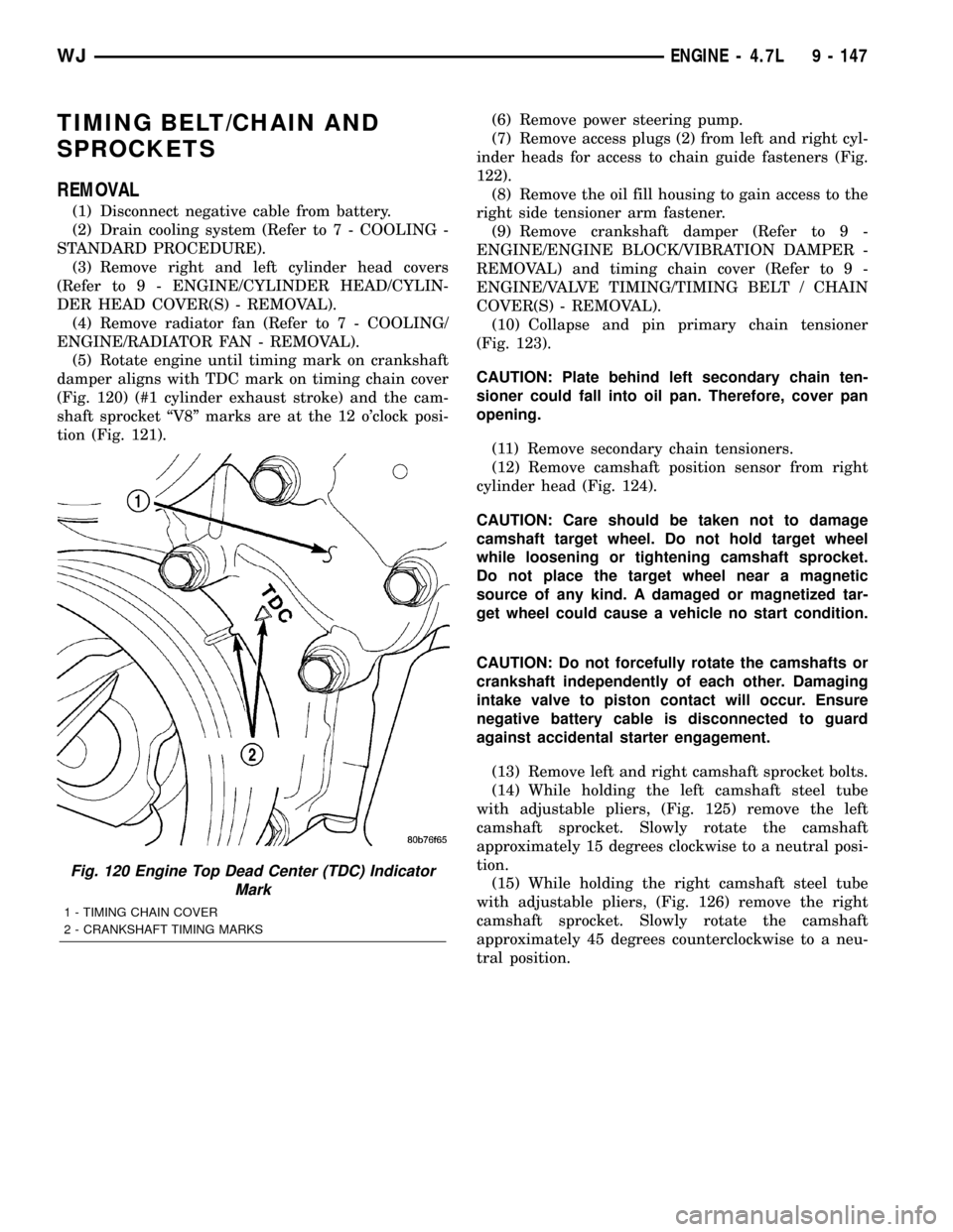
(Fig. 120) (#1 cylinder exhaust stroke) and the cam-
shaft sprocket ªV8º marks are at the 12 o'clock posi-
tion (Fig. 121).(6) Remove power steering pump.
(7) Remove access plugs (2) from left and right cyl-
inder heads for access to chain guide fasteners (Fig.
122).
(8) Remove the oil fill housing to gain access to the
right side tensioner arm fastener.
(9) Remove crankshaft damper (Refer to 9 -
ENGINE/ENGINE BLOCK/VIBRATION DAMPER -
REMOVAL) and timing chain cover (Refer to 9 -
ENGINE/VALVE TIMING/TIMING BELT / CHAIN
COVER(S) - REMOVAL).
(10) Collapse and pin primary chain tensioner
(Fig. 123).
CAUTION: Plate behind left secondary chain ten-
sioner could fall into oil pan. Therefore, cover pan
opening.
(11) Remove secondary chain tensioners.
(12) Remove camshaft position sensor from right
cylinder head (Fig. 124).
CAUTION: Care should be taken not to damage
camshaft target wheel. Do not hold target wheel
while loosening or tightening camshaft sprocket.
Do not place the target wheel near a magnetic
source of any kind. A damaged or magnetized tar-
get wheel could cause a vehicle no start condition.
CAUTION: Do not forcefully rotate the camshafts or
crankshaft independently of each other. Damaging
intake valve to piston contact will occur. Ensure
negative battery cable is disconnected to guard
against accidental starter engagement.
(13) Remove left and right camshaft sprocket bolts.
(14) While holding the left camshaft steel tube
with adjustable pliers, (Fig. 125) remove the left
camshaft sprocket. Slowly rotate the camshaft
approximately 15 degrees clockwise to a neutral posi-
tion.
(15) While holding the right camshaft steel tube
with adjustable pliers, (Fig. 126) remove the right
camshaft sprocket. Slowly rotate the camshaft
approximately 45 degrees counterclockwise to a neu-
tral position.
Fig. 120 Engine Top Dead Center (TDC) Indicator
Mark
1 - TIMING CHAIN COVER
2 - CRANKSHAFT TIMING MARKS
WJENGINE - 4.7L 9 - 147
Page 1438 of 2199

(14) Install air tube (or duct) at top of throttle
body.
(15) Install fuel tank cap.
(16) Connect negative battery cable to battery.
(17) Start engine and check for fuel leaks.
FUEL TANK
DESCRIPTION
The fuel tank is constructed of a plastic material.
Its main functions are for fuel storage and for place-
ment of the fuel pump module and certain ORVR
components.
OPERATION
All models pass a full 360 degree rollover test
without fuel leakage. To accomplish this, fuel and
vapor flow controls are required for all fuel tank con-
nections.
A fuel tank check valve(s) is mounted into the top
of the fuel tank (or pump module). Refer to Fuel
Tank Check Valve for additional information.
An evaporation control system is connected to the
check valve(s) to reduce emissions of fuel vapors into
the atmosphere. When fuel evaporates from the fuel
tank, vapors pass through vent hoses or tubes to a
charcoal canister where they are temporarily held.
When the engine is running, the vapors are drawn
into the intake manifold. Certain models are also
equipped with a self-diagnosing system using a Leak
Detection Pump (LDP). Refer to Emission Control
System for additional information.
Refer to ORVR for On-Board Refueling Vapor
Recovery system information.
REMOVAL
WARNING: THE FUEL SYSTEM IS UNDER CON-
STANT FUEL PRESSURE EVEN WITH ENGINE OFF.
PRESSURE MUST BE RELEASED BEFORE SERVIC-
ING FUEL TANK.
Two different procedures may be used to drain fuel
tank (through ORVR control valve opening at top of
fuel tank, or using DRB scan tool). The quickest is
draining through ORVR control valve opening at top
of fuel tank (Fig. 26).
As an alternative procedure, the electric fuel pump
may be activated allowing tank to be drained at fuel
rail connection. Refer to DRB scan tool for fuel pump
activation procedures. Before disconnecting fuel line
at fuel rail, release fuel pressure. Refer to the Fuel
System Pressure Release Procedure for procedures.
Attach end of Special Adapter Hose Tool number
6539 at fuel rail disconnection. Position opposite end
of 6539 to an approved gasoline draining station.Activate fuel pump with DRB and drain tank until
empty.
If electric fuel pump is not operating, tankMUST
be drained through ORVR control valve opening at
top of fuel tank (Fig. 26).
(1) Release fuel system pressure. Refer to Fuel
System Pressure Release Procedure.
(2) Disconnect negative battery cable at battery.
(3) Raise and support vehicle.
(4) Remove left rear wheel/tire.
CAUTION: HANDLE EVAP, LDP AND ORVR VAPOR /
VACUUM LINES VERY CAREFULLY. THESE LINES
AND HOSES MUST BE FIRMLY CONNECTED.
CHECK THE VAPOR/VACUUM LINES AT THE LDP,
LDP FILTER, EVAP CANISTER, EVAP CANISTER
PURGE SOLENOID AND ORVR COMPONENTS FOR
DAMAGE OR LEAKS. IF A LEAK IS PRESENT, A
DIAGNOSTIC TROUBLE CODE (DTC) MAY BE SET.
(5) Clean top of fuel tank at ORVR control valve
(Fig. 26) or (Fig. 27).
(6) Press release tab in direction of arrow in (Fig.
27) and remove ORVR control valve lock ring
(counter-clockwise). Lift up ORVR control slightly.
Using an approved gasoline draining station, drain
tank until empty through this opening.
(7) Remove stone shield behind left/rear wheel
(Fig. 28). Drill out plastic rivets for removal.
(8) Remove 3 LDP mounting bolts (Fig. 29).
(9) Remove support bracket brace bolt (Fig. 30).
(10) Loosen, but do not remove 2 support bracket
nuts at frame rail (Fig. 29).
(11) To separate and lower front section of two-
piece support bracket, remove 3 attaching bolts on
bottom of support bracket (Fig. 30). While lowering
support bracket, disconnect LDP wiring clip (Fig. 31).
(12) Remove hose clamp (Fig. 32) and remove fuel
fill hose from fuel fill tube.
(13) Cut and discard tie wrap from axle vent hose
(Fig. 32).
(14) Disconnect fuel vent hose from fuel vent tube
(Fig. 32).
(15) Disconnect ORVR hose elbow (Fig. 33) at top
of EVAP canister.
(16) Place hydraulic jack to bottom of fuel tank.
(17) Remove fuel tank-to-rear bumper fascia clips
(Fig. 34).
(18) Remove fuel tank heat shield mounting bolts
(Fig. 35).
CAUTION: To protect fuel tank from exhaust heat,
shield must re-installed after tank installation.
WARNING: PLACE SHOP TOWEL AROUND FUEL
LINES TO CATCH ANY EXCESS FUEL.
WJFUEL DELIVERY 14 - 19
FUEL RAIL (Continued)
Page 1493 of 2199
GEAR
TABLE OF CONTENTS
page page
GEAR
DESCRIPTION.........................16
OPERATION...........................16
REMOVAL.............................16
INSTALLATION.........................16
ADJUSTMENTS
STEERING GEAR.....................18
SPECIFICATIONS
POWER STEERING GEAR..............18
SPECIAL TOOLS
POWER STEERING GEAR..............19
PITMAN SHAFT
REMOVAL.............................20INSTALLATION.........................20
PITMAN SHAFT BEARING
REMOVAL.............................22
INSTALLATION.........................22
PITMAN SHAFT SEAL
REMOVAL.............................22
INSTALLATION.........................23
RACK PISTON/VALVE ASSEMBLY
REMOVAL.............................23
INSTALLATION.........................25
STUB SHAFT HOUSING
REMOVAL.............................25
INSTALLATION.........................25
GEAR
DESCRIPTION
The power steering gear is a recirculating ball type
gear (Fig. 1) .
The following gear components can be serviced:
²Pitman Shaft and Cover
²Pitman Shaft Bearings
²Pitman Shaft Oil Seal/Dust Seal
²Stud Shaft Housing with Seal
²O-Rings and Teflon Rings
NOTE: If rack piston assembly is damaged the gear
must be replaced.
OPERATION
The gear acts as a rolling thread between the
worm shaft and rack piston. The worm shaft is sup-
ported by a thrust bearing at the lower end and a
bearing assembly at the upper end. When the worm
shaft is turned the rack piston moves. The rack pis-
ton teeth mesh with the pitman shaft. Turning the
worm shaft turns the pitman shaft, which turns the
steering linkage.
REMOVAL
(1) Place the front wheels in the straight ahead
position with the steering wheel centered and locked.
(2) Remove the air cleaner housing,(Refer to 9 -
ENGINE/AIR INTAKE SYSTEM/AIR CLEANER
HOUSING - REMOVAL).
(3) Drain or siphon the power steering system.(4) Remove the pressure and return lines (Fig.
2)from the steering gear. Refer to hose removal in
this section.
(5) Remove the column coupler shaft bolt (Fig.
2)and remove the shaft from the gear.
(6) Raise and support the vehicle.
(7) Remove the left front wheel and tire assembly.
(8) Remove the pitman arm from gear with Puller
C-4150A.
(9) Remove the windshield washer reservoir,(Refer
to 8 - ELECTRICAL/WIPERS/WASHERS/WASHER
RESERVOIR - REMOVAL).
(10) Remove the steering gear mounting bolts.
Remove the steering gear out of the engine compart-
ment (Fig. 3).
INSTALLATION
(1) Position the steering gear on the frame rail and
install the bolts. Tighten the bolts to 108 N´m (80 ft.
lbs.) torque.
(2) Install the pitman arm and tighten nut to 251
N´m (185 ft. lbs.).
(3) Install windshield washer reservoir,(Refer to 8 -
ELECTRICAL/WIPERS/WASHERS/WASHER RES-
ERVOIR - INSTALLATION).
(4) Install the wheel and tire assembly.
(5) Remove the support and lower the vehicle.
(6) Install the pressure and return hoses to the
steering gear and tighten to 20-38 N´m (14-28 ft.
lbs.).
(7) Install the column coupler shaft.
(8) Install the air cleaner housing,(Refer to 9 -
ENGINE/AIR INTAKE SYSTEM/AIR CLEANER
HOUSING - INSTALLATION).
19 - 16 GEARWJ
Page 1511 of 2199
(11) While the vehicle is in park, use the DRB III
to activate the hydraulic fan to full fan operation and
briefly rev the engine up to 3000 rpm to fully engage
the hydraulic fan.
(12) Check the fluid level add if necessary.
REMOVAL
REMOVAL - 4.0L ENGINE
(1) Remove serpentine drive belt,(Refer to 7 -
COOLING/ACCESSORY DRIVE/DRIVE BELTS -
REMOVAL).
(2) Remove pressure and return hoses from pump
and drain the pump.
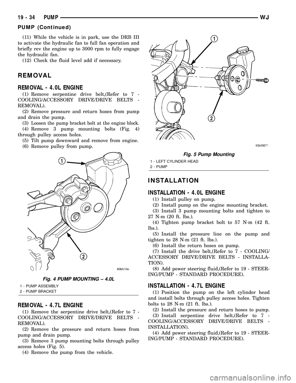
(3)
Loosen the pump bracket bolt at the engine block.
(4) Remove 3 pump mounting bolts (Fig. 4)
through pulley access holes.
(5) Tilt pump downward and remove from engine.
(6) Remove pulley from pump.
REMOVAL - 4.7L ENGINE
(1) Remove the serpentine drive belt,(Refer to 7 -
COOLING/ACCESSORY DRIVE/DRIVE BELTS -
REMOVAL).
(2) Remove the pressure and return hoses from
pump and drain pump.
(3) Remove 3 pump mounting bolts through pulley
access holes (Fig. 5).
(4) Remove the pump from the vehicle.
INSTALLATION
INSTALLATION - 4.0L ENGINE
(1) Install pulley on pump.
(2) Install pump on the engine mounting bracket.
(3) Install 3 pump mounting bolts and tighten to
27 N´m (20 ft. lbs.).
(4) Tighten pump bracket bolt to 57 N´m (42 ft.
lbs.).
(5) Install the pressure line on the pump and
tighten to 28 N´m (21 ft. lbs.).
(6) Install the return hoses on pump.
(7) Install the drive belt,(Refer to 7 - COOLING/
ACCESSORY DRIVE/DRIVE BELTS - INSTALLA-
TION).
(8) Add power steering fluid,(Refer to 19 - STEER-
ING/PUMP - STANDARD PROCEDURE).
INSTALLATION - 4.7L ENGINE
(1) Position the pump on the left cylinder head
and install bolts through pulley access holes. Tighten
bolts to 28 N´m (21 ft. lbs.).
(2) Install the pressure and return hoses to pump.
(3) Install serpentine drive belt,(Refer to 7 -
COOLING/ACCESSORY DRIVE/DRIVE BELTS -
INSTALLATION).
(4) Add power steering fluid,(Refer to 19 - STEER-
ING/PUMP - STANDARD PROCEDURE).
Fig. 4 PUMP MOUNTING ± 4.0L
1 - PUMP ASSEMBLY
2 - PUMP BRACKET
Fig. 5 Pump Mounting
1 - LEFT CYLINDER HEAD
2 - PUMP
19 - 34 PUMPWJ
PUMP (Continued)