reset JEEP GRAND CHEROKEE 2003 WJ / 2.G Owner's Guide
[x] Cancel search | Manufacturer: JEEP, Model Year: 2003, Model line: GRAND CHEROKEE, Model: JEEP GRAND CHEROKEE 2003 WJ / 2.GPages: 2199, PDF Size: 76.01 MB
Page 1343 of 2199

²Step 2: Verify that bolts 1±10, all reached 27
N´m (20 ft. lbs.), by repeating step-1 without loosen-
ing the bolts. Tighten bolts 11 thru 14 to 14 N´m (10
ft. lbs.).
²Step 3: Tighten bolts 1±10, 90 degrees.
²Step 4: Tighten bolts 1±10, 90 degrees, again.
Tighten bolts 11±14, 26 N´m (19 ft. lbs.)
(7) Install the secondary chain and secondary
chain guide (Refer to 9 - ENGINE/VALVE TIMING/
TIMING BELT/CHAIN AND SPROCKETS -
INSTALLATION).
(8) Install the cylinder head access plug.
(9) Re-set and install the right side secondary
chain tensioner (Refer to 9 - ENGINE/VALVE TIM-
ING/TIMING BELT/CHAIN AND SPROCKETS -
INSTALLATION).
(10) Remove Special Tool 8515.
(11) Install the timing chain cover (Refer to 9 -
ENGINE/VALVE TIMING/TIMING BELT / CHAIN
COVER(S) - INSTALLATION).
(12) Install the crankshaft damper (Refer to 9 -
ENGINE/ENGINE BLOCK/VIBRATION DAMPER -
INSTALLATION).
(13) Install accessory drive belt (Refer to 7 -
COOLING/ACCESSORY DRIVE/DRIVE BELTS -
INSTALLATION).
(14) Install the cylinder head cover (Refer to 9 -
ENGINE/CYLINDER HEAD/CYLINDER HEAD
COVER(S) - INSTALLATION).
(15) Install the intake manifold (Refer to 9 -
ENGINE/MANIFOLDS/INTAKE MANIFOLD -
INSTALLATION).
(16) Install oil fill housing onto cylinder head.
(17) Refill the cooling system (Refer to 7 - COOL-
ING - STANDARD PROCEDURE).
(18) Raise the vehicle.
(19) Install the exhaust pipe onto the right
exhaust manifold.
(20) Lower the vehicle.
(21) Reconnect battery negitive cable.
(22) Start the engine and check for leaks.CAMSHAFT(S) - RIGHT
DESCRIPTION
The camshafts consist of powdered metal steel
lobes which are sinter-bonded to a steel tube. A steel
post or nose piece is friction-welded to the steel cam-
shaft tube. Five bearing journals are machined into
the camshaft, four on the steel tube and one on the
steel nose piece. Camshaft end play is controlled by
two thrust walls that border the nose piece journal.
Engine oil enters the hollow camshafts at the third
journal and lubricates every intake lobe rocker
through a drilled passage in the intake lobe.
REMOVAL
CAUTION: When the timing chain is removed and
the cylinder heads are still installed, DO NOT force-
fully rotate the camshafts or crankshaft indepen-
dently of each other. Severe valve and/or piston
damage can occur.
CAUTION: When removing the cam sprocket, timing
chains or camshaft, Failure to use special tool 8350
will result in hydraulic tensioner ratchet over exten-
sion, Requiring timing chain cover removal to re-set
the tensioner ratchet.
(1) Remove the cylinder head covers (Refer to 9 -
ENGINE/CYLINDER HEAD/CYLINDER HEAD
COVER(S) - REMOVAL).
(2) Set engine to TDC cylinder #1, camshaft
sprocket V8 marks at the 12 o'clock position.
(3) Mark one link on the secondary timing chain
on both sides of the V8 mark on the camshaft
sprocket to aid in installation.
CAUTION: Do not hold or pry on the camshaft tar-
get wheel for any reason, Severe damage will occur
to the target wheel. A damaged target wheel could
cause a vehicle no start condition.
(4) Loosen butDO NOTremove the camshaft
sprocket retaining bolt. Leave bolt snug against
sprocket.
NOTE: The timing chain tensioners must be
secured prior to removing the camshaft sprockets.
Failure to secure tensioners will allow the tension-
ers to extend, requiring timing chain cover removal
in order to reset tensioners.
CAUTION: Do not force wedge past the narrowest
point between the chain strands. Damage to the
tensioners may occur.
Fig. 30 Cylinder Head Tightening Sequence
9 - 100 ENGINE - 4.7LWJ
CYLINDER HEAD - RIGHT (Continued)
Page 1394 of 2199
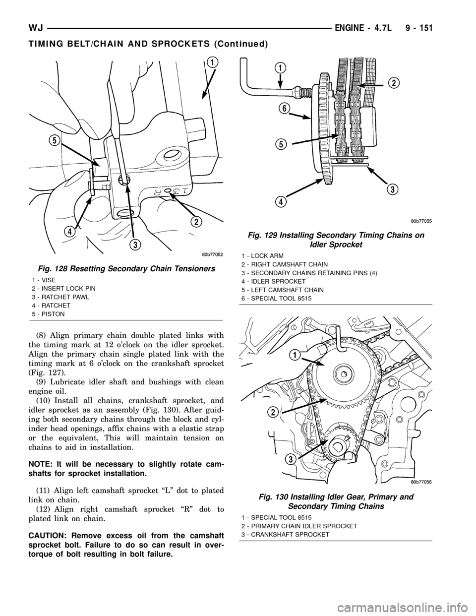
(8) Align primary chain double plated links with
the timing mark at 12 o'clock on the idler sprocket.
Align the primary chain single plated link with the
timing mark at 6 o'clock on the crankshaft sprocket
(Fig. 127).
(9) Lubricate idler shaft and bushings with clean
engine oil.
(10) Install all chains, crankshaft sprocket, and
idler sprocket as an assembly (Fig. 130). After guid-
ing both secondary chains through the block and cyl-
inder head openings, affix chains with a elastic strap
or the equivalent, This will maintain tension on
chains to aid in installation.
NOTE: It will be necessary to slightly rotate cam-
shafts for sprocket installation.
(11) Align left camshaft sprocket ªLº dot to plated
link on chain.
(12) Align right camshaft sprocket ªRº dot to
plated link on chain.
CAUTION: Remove excess oil from the camshaft
sprocket bolt. Failure to do so can result in over-
torque of bolt resulting in bolt failure.
Fig. 128 Resetting Secondary Chain Tensioners
1 - VISE
2 - INSERT LOCK PIN
3 - RATCHET PAWL
4 - RATCHET
5 - PISTON
Fig. 129 Installing Secondary Timing Chains on
Idler Sprocket
1 - LOCK ARM
2 - RIGHT CAMSHAFT CHAIN
3 - SECONDARY CHAINS RETAINING PINS (4)
4 - IDLER SPROCKET
5 - LEFT CAMSHAFT CHAIN
6 - SPECIAL TOOL 8515
Fig. 130 Installing Idler Gear, Primary and
Secondary Timing Chains
1 - SPECIAL TOOL 8515
2 - PRIMARY CHAIN IDLER SPROCKET
3 - CRANKSHAFT SPROCKET
WJENGINE - 4.7L 9 - 151
TIMING BELT/CHAIN AND SPROCKETS (Continued)
Page 1789 of 2199
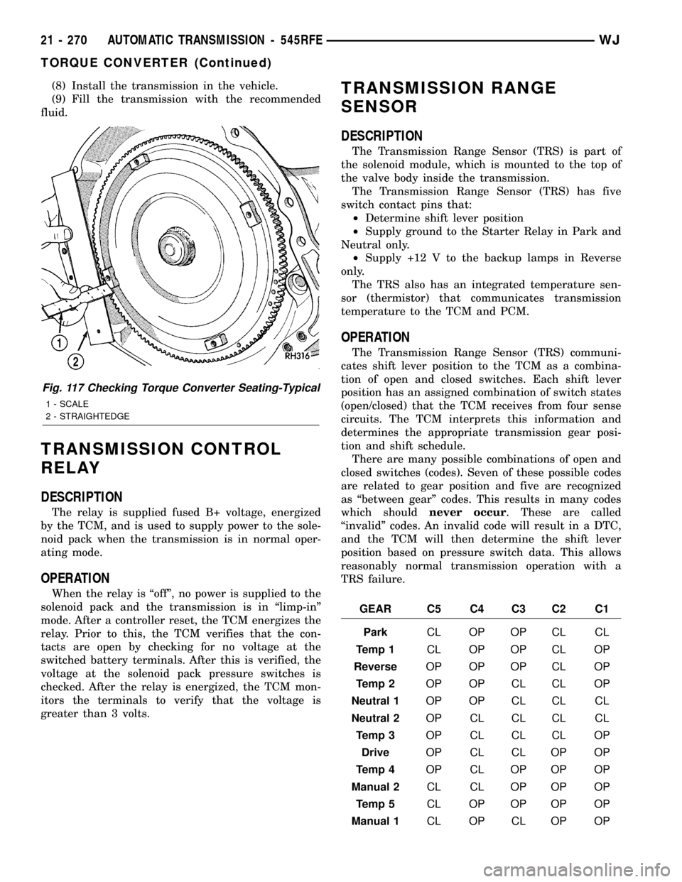
(8) Install the transmission in the vehicle.
(9) Fill the transmission with the recommended
fluid.
TRANSMISSION CONTROL
RELAY
DESCRIPTION
The relay is supplied fused B+ voltage, energized
by the TCM, and is used to supply power to the sole-
noid pack when the transmission is in normal oper-
ating mode.
OPERATION
When the relay is ªoffº, no power is supplied to the
solenoid pack and the transmission is in ªlimp-inº
mode. After a controller reset, the TCM energizes the
relay. Prior to this, the TCM verifies that the con-
tacts are open by checking for no voltage at the
switched battery terminals. After this is verified, the
voltage at the solenoid pack pressure switches is
checked. After the relay is energized, the TCM mon-
itors the terminals to verify that the voltage is
greater than 3 volts.
TRANSMISSION RANGE
SENSOR
DESCRIPTION
The Transmission Range Sensor (TRS) is part of
the solenoid module, which is mounted to the top of
the valve body inside the transmission.
The Transmission Range Sensor (TRS) has five
switch contact pins that:
²Determine shift lever position
²Supply ground to the Starter Relay in Park and
Neutral only.
²Supply +12 V to the backup lamps in Reverse
only.
The TRS also has an integrated temperature sen-
sor (thermistor) that communicates transmission
temperature to the TCM and PCM.
OPERATION
The Transmission Range Sensor (TRS) communi-
cates shift lever position to the TCM as a combina-
tion of open and closed switches. Each shift lever
position has an assigned combination of switch states
(open/closed) that the TCM receives from four sense
circuits. The TCM interprets this information and
determines the appropriate transmission gear posi-
tion and shift schedule.
There are many possible combinations of open and
closed switches (codes). Seven of these possible codes
are related to gear position and five are recognized
as ªbetween gearº codes. This results in many codes
which shouldnever occur. These are called
ªinvalidº codes. An invalid code will result in a DTC,
and the TCM will then determine the shift lever
position based on pressure switch data. This allows
reasonably normal transmission operation with a
TRS failure.
GEAR C5 C4 C3 C2 C1
ParkCL OP OP CL CL
Temp 1CL OP OP CL OP
ReverseOP OP OP CL OP
Temp 2OP OP CL CL OP
Neutral 1OP OP CL CL CL
Neutral 2OP CL CL CL CL
Temp 3OP CL CL CL OP
DriveOP CL CL OP OP
Temp 4OP CL OP OP OP
Manual 2CL CL OP OP OP
Temp 5CL OP OP OP OP
Manual 1CL OP CL OP OP
Fig. 117 Checking Torque Converter Seating-Typical
1 - SCALE
2 - STRAIGHTEDGE
21 - 270 AUTOMATIC TRANSMISSION - 545RFEWJ
TORQUE CONVERTER (Continued)
Page 1950 of 2199
HEADLINER
REMOVAL
CAUTION: The headliner is a one-piece, molded
component. It has limited flexibility and must not be
bent. Damage may possibly result.
(1) Record radio presets and disconnect negative
battery cable.
(2) Remove A pillar trim moldings (Refer to 23 -
BODY/INTERIOR/A-PILLAR TRIM - REMOVAL).
(3) Remove B pillar upper trim moldings (Refer to
23 - BODY/INTERIOR/B-PILLAR UPPER TRIM -
REMOVAL).
(4) Remove C pillar trim moldings (Refer to 23 -
BODY/INTERIOR/C-PILLAR TRIM - REMOVAL).
(5) Remove D pillar trim molding (Refer to 23 -
BODY/INTERIOR/D-PILLAR TRIM - REMOVAL).
(6) Remove the sun visors (Refer to 23 - BODY/IN-
TERIOR/SUN VISOR - REMOVAL).
(7) Disconnect the vanity lamp electrical connector.
(8) Remove assist handles from roof rails (Refer to
23 - BODY/INTERIOR/ASSIST HANDLE - REMOV-
AL).
(9) Remove dome lamp and overhead console, if
equipped.
(10) Remove rear cargo/dome lamp.
(11) Remove sun roof pinch welt, if equipped.
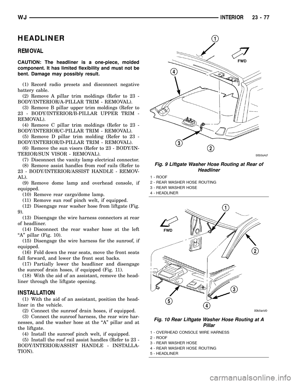
(12) Disengage rear washer hose from liftgate (Fig.
9).
(13) Disengage the wire harness connectors at rear
of headliner.
(14) Disconnect the rear washer hose at the left
ªAº pillar (Fig. 10).
(15) Disengage the wire harness for the sunroof, if
equipped.
(16) Fold down the rear seats, move the front seats
full forward, and lower the front seat backs.
(17) Partially lower the headliner and disengage
the sunroof drain hoses, if equipped (Fig. 11).
(18) With the aid of an assistant, remove the head-
liner through the liftgate opening.
INSTALLATION
(1) With the aid of an assistant, position the head-
liner in the vehicle.
(2) Connect the sunroof drain hoses, if equipped.
(3) Connect the sunroof harness, the rear wire har-
nesses, and the washer hose at the ªAº pillar and at
the liftgate.
(4) Install the sunroof pinch welt, if equipped.
(5) Install the roof rail assist handles (Refer to 23 -
BODY/INTERIOR/ASSIST HANDLE - INSTALLA-
TION).
Fig. 9 Liftgate Washer Hose Routing at Rear of
Headliner
1 - ROOF
2 - REAR WASHER HOSE ROUTING
3 - REAR WASHER HOSE
4 - HEADLINER
Fig. 10 Rear Liftgate Washer Hose Routing at A
Pillar
1 - OVERHEAD CONSOLE WIRE HARNESS
2 - ROOF
3 - REAR WASHER HOSE
4 - REAR WASHER HOSE ROUTING
5 - HEADLINER
WJINTERIOR 23 - 77
Page 1974 of 2199

CONTROL MODULE
REMOVAL
(1) Move the glass panel to the fully closed posi-
tion.
(2) Remove the A-pillar trim. (Refer to 23 - BODY/
INTERIOR/A-PILLAR TRIM - REMOVAL)
(3) Remove the sun visors. (Refer to 23 - BODY/
INTERIOR/SUN VISOR - REMOVAL)
(4) Remove the overhead console. (Refer to 8 -
ELECTRICAL/OVERHEAD CONSOLE - REMOVAL)
(5) Lower headliner as necessary to gain access to
the sunroof express module.
(6) Disconnect the express module wire harness
connectors.
(7) Remove express module screw.
(8) Remove express module from the keyway by
sliding module towards the center of the vehicle.
INSTALLATION
(1) Insert sunroof express module in the keyway
located in the sunroof module and slide the module
outward to lock it into position.
(2) Install the sunroof express module screw.
(3) Connect the wire connectors to the sunroof
express module.
(4) Install the headliner into position.
(5) Install the overhead console. (Refer to 8 -
ELECTRICAL/OVERHEAD CONSOLE - INSTALLA-
TION)
(6) Install the sun visors. (Refer to 23 - BODY/IN-
TERIOR/SUN VISOR - INSTALLATION)
(7) Install the A-pillar trim. (Refer to 23 - BODY/
INTERIOR/A-PILLAR TRIM - INSTALLATION)
(8) Test sunroof operation, adjust if necessary.
(Refer to 23 - BODY/SUNROOF/GLASS PANEL -
ADJUSTMENTS)
DRIVE MOTOR
REMOVAL
CAUTION: The sunroof system is timed from the
factory so that the motor shuts off automatically
when the sunroof window reaches a certain posi-
tion. Extreme care must be taken when removing
the motor, timing may be thrown off causing possi-
ble damage to the sunroof system. Anytime the
motor is removed from the sunroof assembly the
sunroof glass panel must be in the FULLY CLOSED
POSITION or the unit will be out of timing. The drive
motor cannot be reset to the park position after
being removed.CAUTION: The sunroof motor should only be pow-
ered through the vehicle battery and sunroof wire
harness. Applying power to the sunroof motor leads
will cause failure of the control module.
(1) Move glass panel to the fully closed position.
(2) Remove the A-pillar trim. (Refer to 23 - BODY/
INTERIOR/A-PILLAR TRIM - REMOVAL)
(3) Remove the B-pillar upper trim. (Refer to 23 -
BODY/INTERIOR/B-PILLAR UPPER TRIM -
REMOVAL)
(4) Remove the C-pillar trim. (Refer to 23 - BODY/
INTERIOR/C-PILLAR TRIM - REMOVAL)
(5) Remove the D-pillar trim. (Refer to 23 - BODY/
INTERIOR/D-PILLAR TRIM - REMOVAL)
(6) Remove the sunvisors. (Refer to 23 - BODY/IN-
TERIOR/SUN VISOR - REMOVAL)
(7) Remove the overhead console. (Refer to 8 -
ELECTRICAL/OVERHEAD CONSOLE - REMOVAL)
(8) Disconnect the control switch wire connector.
(9) Remove headliner as necessary to gain access
to sunroof drive motor. Refer to Headliner Removal
and Installation for proper procedures.
(10) Disconnect the drive motor wire harness con-
nectors (Fig. 3).
(11) Remove drive motor fasteners and remove
motor from the sunroof housing.
INSTALLATION
(1) Ensure that the window is in the fully closed
position before mounting the motor. If motor fails
with the window in the open position the sunroof
glass panel timing will have to be timed. The new
motor comes in the fully closed position and with a
gage for setting cable timing. (Refer to 23 - BODY/
SUNROOF/GLASS PANEL - ADJUSTMENTS - TIM-
ING)
(2) Place drive motor into position on the sunroof
housing and install fasteners.
Fig. 3 Sunroof Drive Motor and Express Module
1 - EXPRESS MODULE
2 - SCREW
WJSUNROOF 23 - 101
Page 2084 of 2199
(5) Install the new diode in the harness, making
sure current flow is correct. If necessary refer to the
appropriate wiring diagram for current flow.
(6) Solder the connection together using rosin core
type solder only.Do not use acid core solder.
(7) Tape the diode to the harness using electrical
tape making, sure the diode is completely sealed
from the elements.
(8) Re-connect the battery, and test affected sys-
tems.SPECIFICATIONS
A/C APPLICATION TABLE
Item Description Notes
VEHICLE WJ - Grand
Cherokee
SYSTEM R134a w/
expansion valve
COMPRESSOR Nippondenso
10PA17ND-8 PAG oil
Freeze±up
ControlEvaporator Probe Evaporator
mounted
Low psi Control opens < 22 psi -
resets > 34-38 psi
High psi Control opens > 450-490
psi - resets <
270-330 psiline mounted
CONTROL
HEADManual type manual
controls
Automatic Zone
Control (AZC)Automatic
Zone Control
(AZC) with
dual infrared
sensing
Mode Doors Vacuum actuators
(manual)electric
actuator
(AZC)
Blend Door Electric actuator (manual and
AZC)
Blend Door
(passenger)Electric actuator (AZC only)
Recirculation
DoorVacuum actuator
(manual)electric
actuator
(AZC)
Blower Motor Hardwired to
control head
resistor block
(manual),
blower
controller (AZC)
COOLING FAN Hybrid - viscous
clutch/electricPCM output
CLUTCH
Control Relay PCM
controlled
Draw
2.0-3.9 amps @ 12 V 0.5V@ 70É F
Gap 0.0169-0.0319
DRB IIIT
Reads TPS, RPM, A/C
switch
Actuators Clutch relay
WJHEATING & AIR CONDITIONING 24 - 7
HEATING & AIR CONDITIONING (Continued)
Page 2095 of 2199
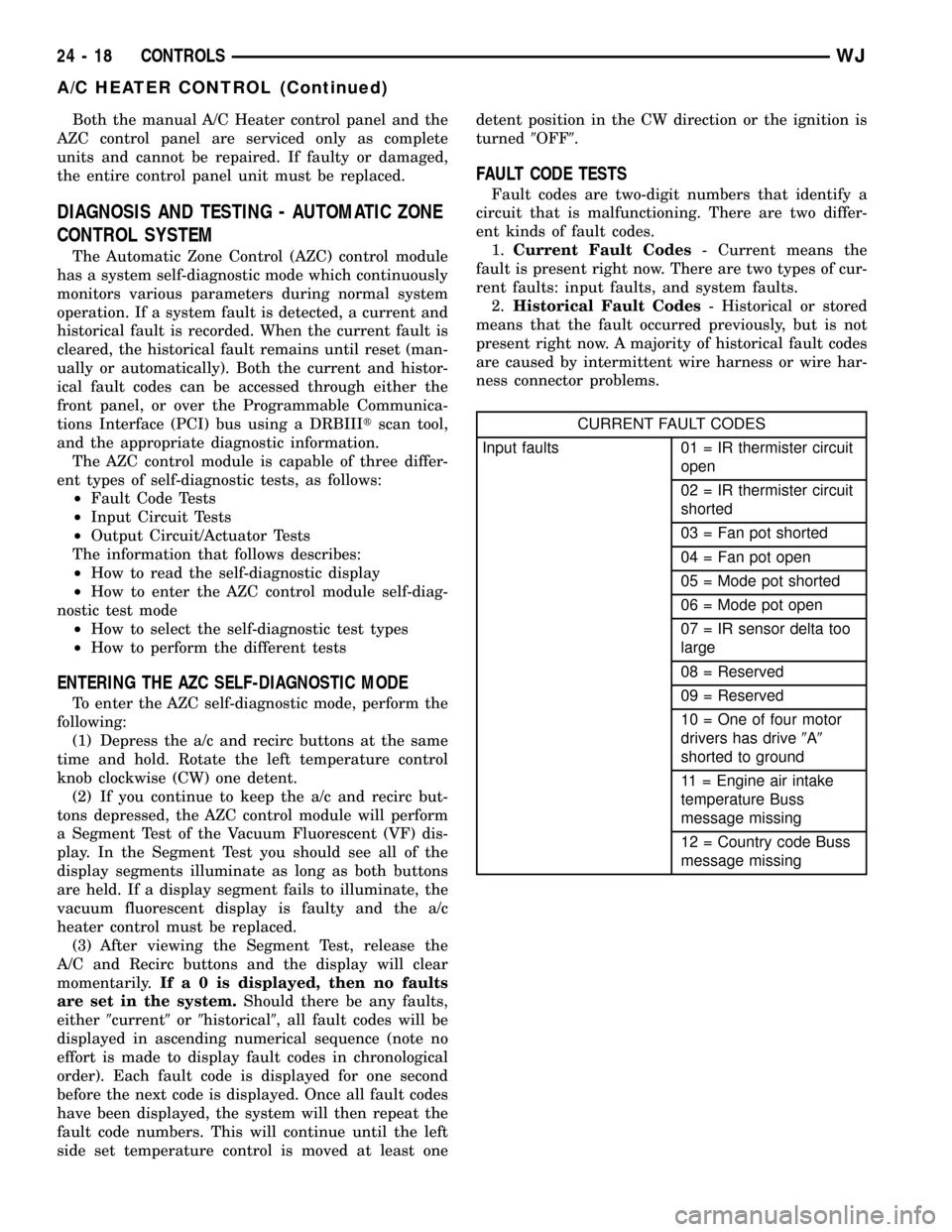
Both the manual A/C Heater control panel and the
AZC control panel are serviced only as complete
units and cannot be repaired. If faulty or damaged,
the entire control panel unit must be replaced.
DIAGNOSIS AND TESTING - AUTOMATIC ZONE
CONTROL SYSTEM
The Automatic Zone Control (AZC) control module
has a system self-diagnostic mode which continuously
monitors various parameters during normal system
operation. If a system fault is detected, a current and
historical fault is recorded. When the current fault is
cleared, the historical fault remains until reset (man-
ually or automatically). Both the current and histor-
ical fault codes can be accessed through either the
front panel, or over the Programmable Communica-
tions Interface (PCI) bus using a DRBIIItscan tool,
and the appropriate diagnostic information.
The AZC control module is capable of three differ-
ent types of self-diagnostic tests, as follows:
²Fault Code Tests
²Input Circuit Tests
²Output Circuit/Actuator Tests
The information that follows describes:
²How to read the self-diagnostic display
²How to enter the AZC control module self-diag-
nostic test mode
²How to select the self-diagnostic test types
²How to perform the different tests
ENTERING THE AZC SELF-DIAGNOSTIC MODE
To enter the AZC self-diagnostic mode, perform the
following:
(1) Depress the a/c and recirc buttons at the same
time and hold. Rotate the left temperature control
knob clockwise (CW) one detent.
(2) If you continue to keep the a/c and recirc but-
tons depressed, the AZC control module will perform
a Segment Test of the Vacuum Fluorescent (VF) dis-
play. In the Segment Test you should see all of the
display segments illuminate as long as both buttons
are held. If a display segment fails to illuminate, the
vacuum fluorescent display is faulty and the a/c
heater control must be replaced.
(3) After viewing the Segment Test, release the
A/C and Recirc buttons and the display will clear
momentarily.Ifa0isdisplayed, then no faults
are set in the system.Should there be any faults,
either9current9or9historical9, all fault codes will be
displayed in ascending numerical sequence (note no
effort is made to display fault codes in chronological
order). Each fault code is displayed for one second
before the next code is displayed. Once all fault codes
have been displayed, the system will then repeat the
fault code numbers. This will continue until the left
side set temperature control is moved at least onedetent position in the CW direction or the ignition is
turned9OFF9.
FAULT CODE TESTS
Fault codes are two-digit numbers that identify a
circuit that is malfunctioning. There are two differ-
ent kinds of fault codes.
1.Current Fault Codes- Current means the
fault is present right now. There are two types of cur-
rent faults: input faults, and system faults.
2.Historical Fault Codes- Historical or stored
means that the fault occurred previously, but is not
present right now. A majority of historical fault codes
are caused by intermittent wire harness or wire har-
ness connector problems.
CURRENT FAULT CODES
Input faults 01 = IR thermister circuit
open
02 = IR thermister circuit
shorted
03 = Fan pot shorted
04 = Fan pot open
05 = Mode pot shorted
06 = Mode pot open
07 = IR sensor delta too
large
08 = Reserved
09 = Reserved
10 = One of four motor
drivers has drive9A9
shorted to ground
11 = Engine air intake
temperature Buss
message missing
12 = Country code Buss
message missing
24 - 18 CONTROLSWJ
A/C HEATER CONTROL (Continued)