Panel JEEP GRAND CHEROKEE 2003 WJ / 2.G Workshop Manual
[x] Cancel search | Manufacturer: JEEP, Model Year: 2003, Model line: GRAND CHEROKEE, Model: JEEP GRAND CHEROKEE 2003 WJ / 2.GPages: 2199, PDF Size: 76.01 MB
Page 2163 of 2199
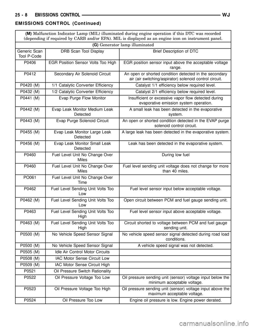
(M)Malfunction Indicator Lamp (MIL) illuminated during engine operation if this DTC was recorded
(depending if required by CARB and/or EPA). MIL is displayed as an engine icon on instrument panel.
(G)Generator lamp illuminated
Generic Scan
Tool P-CodeDRB Scan Tool Display Brief Description of DTC
P0406 EGR Position Sensor Volts Too High EGR position sensor input above the acceptable voltage
range.
P0412 Secondary Air Solenoid Circuit An open or shorted condition detected in the secondary
air (air switching/aspirator) solenoid control circuit.
P0420 (M) 1/1 Catalytic Converter Efficiency Catalyst 1/1 efficiency below required level.
P0432 (M) 1/2 Catalytic Converter Efficiency Catalyst 2/1 efficiency below required level.
P0441 (M) Evap Purge Flow Monitor Insufficient or excessive vapor flow detected during
evaporative emission system operation.
P0442 (M) Evap Leak Monitor Medium Leak
DetectedA small leak has been detected in the evaporative
system.
P0443 (M) Evap Purge Solenoid Circuit An open or shorted condition detected in the EVAP purge
solenoid control circuit.
P0455 (M) Evap Leak Monitor Large Leak
DetectedA large leak has been detected in the evaporative system.
P0456 (M) Evap Leak Monitor Small Leak
DetectedLeak has been detected in the evaporative system.
P0460 Fuel Level Unit No Change Over
MilesDuring low fuel
P0460 Fuel Level Unit No Change Over
MilesFuel level sending unit voltage does not change for more
than 40 miles.
PO061 Fuel Level Unit No Change Over
Time
P0462 Fuel Level Sending Unit Volts Too
LowFuel level sensor input below acceptable voltage.
P0462 (M) Fuel Level Sending Unit Volts Too
LowOpen circuit between PCM and fuel gauge sending unit.
P0463 Fuel Level Sending Unit Volts Too
HighFuel level sensor input above acceptable voltage.
P0463 (M) Fuel Level Sending Unit Volts Too
HighCircuit shorted to voltage between PCM and fuel gauge
sending unit.
P0500 (M) No Vehicle Speed Sensor Signal No vehicle speed sensor signal detected during road load
conditions.
P0500 (M) No Vehicle Speed Sensor Signal A vehicle speed signal was not detected.
P0505 (M) Idle Air Control Motor Circuits
P0508 (M) IAC Motor Sense Circuit Low
P0509 (M) IAC Motor Sense Circuit High
P0521 Oil Pressure Switch Rationality
P0522 Oil Pressure Voltage Too Low Oil pressure sending unit (sensor) voltage input below the
minimum acceptable voltage.
P0523 Oil Pressure Voltage Too High Oil pressure sending unit (sensor) voltage input above the
maximum acceptable voltage.
P0524 Oil Pressure Too Low Engine oil pressure is low. Engine power derated.
25 - 8 EMISSIONS CONTROLWJ
EMISSIONS CONTROL (Continued)
Page 2164 of 2199
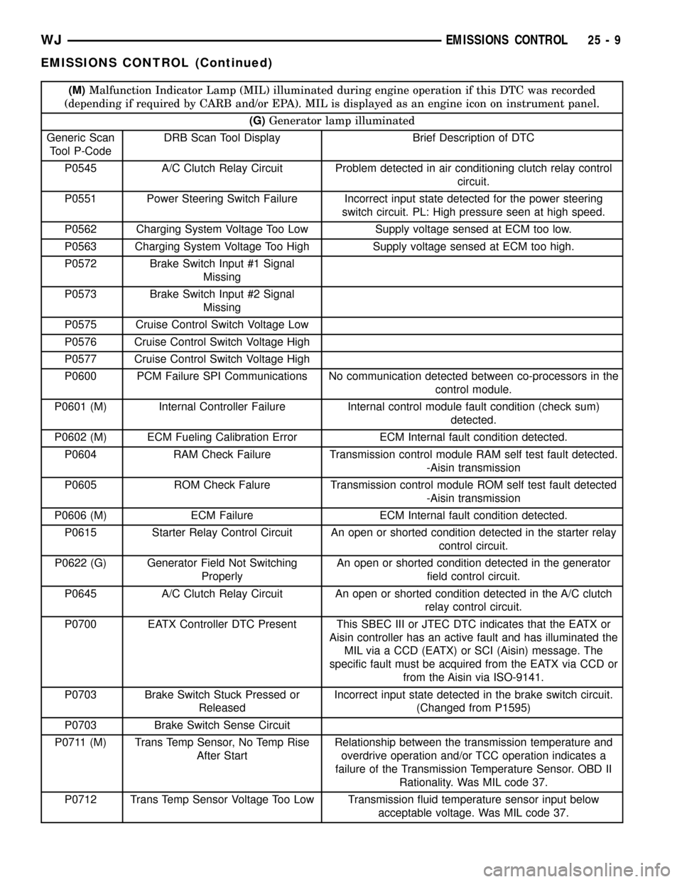
(M)Malfunction Indicator Lamp (MIL) illuminated during engine operation if this DTC was recorded
(depending if required by CARB and/or EPA). MIL is displayed as an engine icon on instrument panel.
(G)Generator lamp illuminated
Generic Scan
Tool P-CodeDRB Scan Tool Display Brief Description of DTC
P0545 A/C Clutch Relay Circuit Problem detected in air conditioning clutch relay control
circuit.
P0551 Power Steering Switch Failure Incorrect input state detected for the power steering
switch circuit. PL: High pressure seen at high speed.
P0562 Charging System Voltage Too Low Supply voltage sensed at ECM too low.
P0563 Charging System Voltage Too High Supply voltage sensed at ECM too high.
P0572 Brake Switch Input #1 Signal
Missing
P0573 Brake Switch Input #2 Signal
Missing
P0575 Cruise Control Switch Voltage Low
P0576 Cruise Control Switch Voltage High
P0577 Cruise Control Switch Voltage High
P0600 PCM Failure SPI Communications No communication detected between co-processors in the
control module.
P0601 (M) Internal Controller Failure Internal control module fault condition (check sum)
detected.
P0602 (M) ECM Fueling Calibration Error ECM Internal fault condition detected.
P0604 RAM Check Failure Transmission control module RAM self test fault detected.
-Aisin transmission
P0605 ROM Check Falure Transmission control module ROM self test fault detected
-Aisin transmission
P0606 (M) ECM Failure ECM Internal fault condition detected.
P0615 Starter Relay Control Circuit An open or shorted condition detected in the starter relay
control circuit.
P0622 (G) Generator Field Not Switching
ProperlyAn open or shorted condition detected in the generator
field control circuit.
P0645 A/C Clutch Relay Circuit An open or shorted condition detected in the A/C clutch
relay control circuit.
P0700 EATX Controller DTC Present This SBEC III or JTEC DTC indicates that the EATX or
Aisin controller has an active fault and has illuminated the
MIL via a CCD (EATX) or SCI (Aisin) message. The
specific fault must be acquired from the EATX via CCD or
from the Aisin via ISO-9141.
P0703 Brake Switch Stuck Pressed or
ReleasedIncorrect input state detected in the brake switch circuit.
(Changed from P1595)
P0703 Brake Switch Sense Circuit
P0711 (M) Trans Temp Sensor, No Temp Rise
After StartRelationship between the transmission temperature and
overdrive operation and/or TCC operation indicates a
failure of the Transmission Temperature Sensor. OBD II
Rationality. Was MIL code 37.
P0712 Trans Temp Sensor Voltage Too Low Transmission fluid temperature sensor input below
acceptable voltage. Was MIL code 37.
WJEMISSIONS CONTROL 25 - 9
EMISSIONS CONTROL (Continued)
Page 2165 of 2199
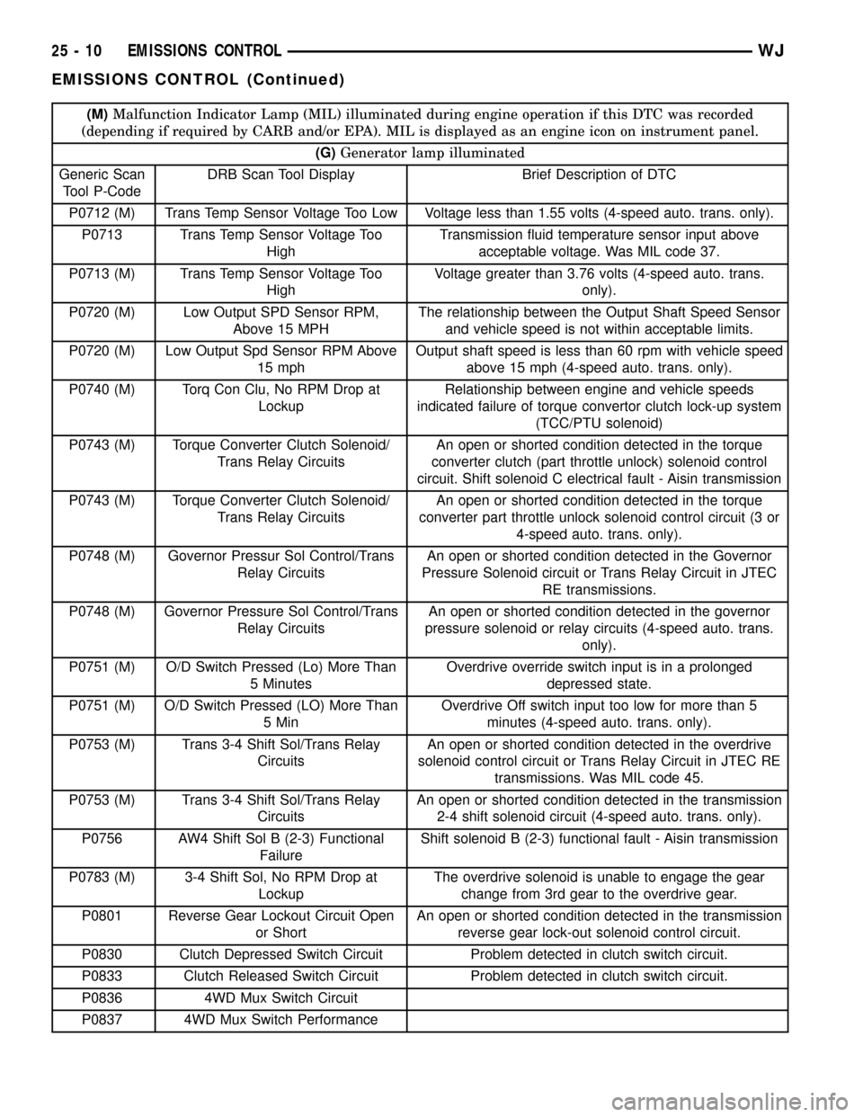
(M)Malfunction Indicator Lamp (MIL) illuminated during engine operation if this DTC was recorded
(depending if required by CARB and/or EPA). MIL is displayed as an engine icon on instrument panel.
(G)Generator lamp illuminated
Generic Scan
Tool P-CodeDRB Scan Tool Display Brief Description of DTC
P0712 (M) Trans Temp Sensor Voltage Too Low Voltage less than 1.55 volts (4-speed auto. trans. only).
P0713 Trans Temp Sensor Voltage Too
HighTransmission fluid temperature sensor input above
acceptable voltage. Was MIL code 37.
P0713 (M) Trans Temp Sensor Voltage Too
HighVoltage greater than 3.76 volts (4-speed auto. trans.
only).
P0720 (M) Low Output SPD Sensor RPM,
Above 15 MPHThe relationship between the Output Shaft Speed Sensor
and vehicle speed is not within acceptable limits.
P0720 (M) Low Output Spd Sensor RPM Above
15 mphOutput shaft speed is less than 60 rpm with vehicle speed
above 15 mph (4-speed auto. trans. only).
P0740 (M) Torq Con Clu, No RPM Drop at
LockupRelationship between engine and vehicle speeds
indicated failure of torque convertor clutch lock-up system
(TCC/PTU solenoid)
P0743 (M) Torque Converter Clutch Solenoid/
Trans Relay CircuitsAn open or shorted condition detected in the torque
converter clutch (part throttle unlock) solenoid control
circuit. Shift solenoid C electrical fault - Aisin transmission
P0743 (M) Torque Converter Clutch Solenoid/
Trans Relay CircuitsAn open or shorted condition detected in the torque
converter part throttle unlock solenoid control circuit (3 or
4-speed auto. trans. only).
P0748 (M) Governor Pressur Sol Control/Trans
Relay CircuitsAn open or shorted condition detected in the Governor
Pressure Solenoid circuit or Trans Relay Circuit in JTEC
RE transmissions.
P0748 (M) Governor Pressure Sol Control/Trans
Relay CircuitsAn open or shorted condition detected in the governor
pressure solenoid or relay circuits (4-speed auto. trans.
only).
P0751 (M) O/D Switch Pressed (Lo) More Than
5 MinutesOverdrive override switch input is in a prolonged
depressed state.
P0751 (M) O/D Switch Pressed (LO) More Than
5 MinOverdrive Off switch input too low for more than 5
minutes (4-speed auto. trans. only).
P0753 (M) Trans 3-4 Shift Sol/Trans Relay
CircuitsAn open or shorted condition detected in the overdrive
solenoid control circuit or Trans Relay Circuit in JTEC RE
transmissions. Was MIL code 45.
P0753 (M) Trans 3-4 Shift Sol/Trans Relay
CircuitsAn open or shorted condition detected in the transmission
2-4 shift solenoid circuit (4-speed auto. trans. only).
P0756 AW4 Shift Sol B (2-3) Functional
FailureShift solenoid B (2-3) functional fault - Aisin transmission
P0783 (M) 3-4 Shift Sol, No RPM Drop at
LockupThe overdrive solenoid is unable to engage the gear
change from 3rd gear to the overdrive gear.
P0801 Reverse Gear Lockout Circuit Open
or ShortAn open or shorted condition detected in the transmission
reverse gear lock-out solenoid control circuit.
P0830 Clutch Depressed Switch Circuit Problem detected in clutch switch circuit.
P0833 Clutch Released Switch Circuit Problem detected in clutch switch circuit.
P0836 4WD Mux Switch Circuit
P0837 4WD Mux Switch Performance
25 - 10 EMISSIONS CONTROLWJ
EMISSIONS CONTROL (Continued)
Page 2166 of 2199
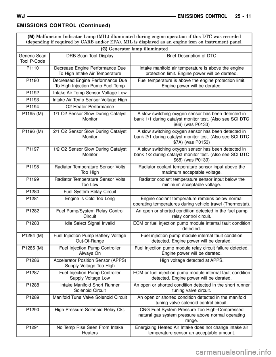
(M)Malfunction Indicator Lamp (MIL) illuminated during engine operation if this DTC was recorded
(depending if required by CARB and/or EPA). MIL is displayed as an engine icon on instrument panel.
(G)Generator lamp illuminated
Generic Scan
Tool P-CodeDRB Scan Tool Display Brief Description of DTC
P1110 Decrease Engine Performance Due
To High Intake Air TemperatureIntake manifold air temperature is above the engine
protection limit. Engine power will be derated.
P1180 Decreased Engine Performance Due
To High Injection Pump Fuel TempFuel temperature is above the engine protection limit.
Engine power will be derated.
P1192 Intake Air Temp Sensor Voltage Low
P1193 Intake Air Temp Sensor Voltage High
P1194 O2 Heater Performance
P1195 (M) 1/1 O2 Sensor Slow During Catalyst
MonitorA slow switching oxygen sensor has been detected in
bank 1/1 during catalyst monitor test. (Also see SCI DTC
$66) (was P0133)
P1196 (M) 2/1 O2 Sensor Slow During Catalyst
MonitorA slow switching oxygen sensor has been detected in
bank 2/1 during catalyst monitor test. (Also see SCI DTC
$7A) (was P0153)
P1197 1/2 O2 Sensor Slow During Catalyst
MonitorA slow switching oxygen sensor has been detected in
bank 1/2 during catalyst monitor test. (Also see SCI DTC
$68) (was P0139)
P1198 Radiator Temperature Sensor Volts
Too HighRadiator coolant temperature sensor input above the
maximum acceptable voltage.
P1199 Radiator Temperature Sensor Volts
Too LowRadiator coolant temperature sensor input below the
minimum acceptable voltage.
P1280 Fuel System Relay Circuit
P1281 Engine is Cold Too Long Engine coolant temperature remains below normal
operating temperatures during vehicle travel (Thermostat).
P1282 Fuel Pump/System Relay Control
CircuitAn open or shorted condition detected in the fuel pump
relay control circuit.
P1283 Idle Select Signal Invalid ECM or fuel injection pump module internal fault condition
detected.
P1284 (M) Fuel Injection Pump Battery Voltage
Out-Of-RangeFuel injection pump module internal fault condition
detected. Engine power will be derated.
P1285 (M) Fuel Injection Pump Controller
Always OnFuel injection pump module relay circuit failure detected.
Engine power will be derated.
P1286 Accelerator Position Sensor (APPS)
Supply Voltage Too HighHigh voltage detected at APPS.
P1287 Fuel Injection Pump Controller
Supply Voltage LowECM or fuel injection pump module internal fault condition
detected. Engine power will be derated.
P1288 Intake Manifold Short Runner
Solenoid CircuitAn open or shorted condition detected in the short runner
tuning valve circuit.
P1289 Manifold Tune Valve Solenoid Circuit An open or shorted condition detected in the manifold
tuning valve solenoid control circuit.
P1290 High Pressure Solenoid Relay Ckt. CNG Fuel System Pressure Too High±Compressed
natural gas system pressure above normal operating
range.
P1291 No Temp Rise Seen From Intake
HeatersEnergizing Heated Air Intake does not change intake air
temperature sensor an acceptable amount.
WJEMISSIONS CONTROL 25 - 11
EMISSIONS CONTROL (Continued)
Page 2167 of 2199
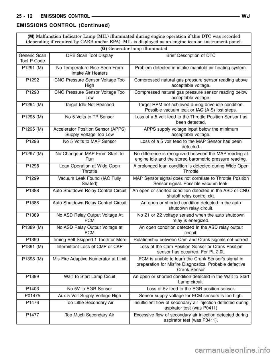
(M)Malfunction Indicator Lamp (MIL) illuminated during engine operation if this DTC was recorded
(depending if required by CARB and/or EPA). MIL is displayed as an engine icon on instrument panel.
(G)Generator lamp illuminated
Generic Scan
Tool P-CodeDRB Scan Tool Display Brief Description of DTC
P1291 (M) No Temperature Rise Seen From
Intake Air HeatersProblem detected in intake manifold air heating system.
P1292 CNG Pressure Sensor Voltage Too
HighCompressed natural gas pressure sensor reading above
acceptable voltage.
P1293 CNG Pressure Sensor Voltage Too
LowCompressed natural gas pressure sensor reading below
acceptable voltage.
P1294 (M) Target Idle Not Reached Target RPM not achieved during drive idle condition.
Possible vacuum leak or IAC (AIS) lost steps.
P1295 (M) No 5 Volts to TP Sensor Loss of a 5 volt feed to the Throttle Position Sensor has
been detected.
P1295 (M) Accelerator Position Sensor (APPS)
Supply Voltage Too LowAPPS supply voltage input below the minimum
acceptable voltage.
P1296 No 5 Volts to MAP Sensor Loss of a 5 volt feed to the MAP Sensor has been
detected.
P1297 (M) No Change in MAP From Start To
RunNo difference is recognized between the MAP reading at
engine idle and the stored barometric pressure reading.
P1298 Lean Operation at Wide Open
ThrottleA prolonged lean condition is detected during Wide Open
Throttle
P1299 Vacuum Leak Found (IAC Fully
Seated)MAP Sensor signal does not correlate to Throttle Position
Sensor signal. Possible vacuum leak.
P1388 Auto Shutdown Relay Control Circuit An open or shorted condition detected in the ASD or CNG
shutoff relay control ckt.
P1388 Auto Shutdown Relay Control Circuit An open or shorted condition detected in the auto
shutdown relay circuit.
P1389 No ASD Relay Output Voltage At
PCMNo Z1 or Z2 voltage sensed when the auto shutdown
relay is energized.
P1389 (M) No ASD Relay Output Voltage at
PCMAn open condition detected In the ASD relay output
circuit.
P1390 Timing Belt Skipped 1 Tooth or More Relationship between Cam and Crank signals not correct
P1391 (M) Intermittent Loss of CMP or CKP Loss of the Cam Position Sensor or Crank Position
sensor has occurred. For PL 2.0L
P1398 (M) Mis-Fire Adaptive Numerator at Limit PCM is unable to learn the Crank Sensor's signal in
preparation for Misfire Diagnostics. Probable defective
Crank Sensor
P1399 Wait To Start Lamp Cicuit An open or shorted condition detected in the Wait to Start
Lamp circuit.
P1403 No 5V to EGR Sensor Loss of 5v feed to the EGR position sensor.
P01475 Aux 5 Volt Supply Voltage High Sensor supply voltage for ECM sensors is too high.
P1476 Too Little Secondary Air Insufficient flow of secondary air injection detected during
aspirator test (was P0411)
P1477 Too Much Secondary Air Excessive flow of secondary air injection detected during
aspirator test (was P0411).
25 - 12 EMISSIONS CONTROLWJ
EMISSIONS CONTROL (Continued)
Page 2168 of 2199
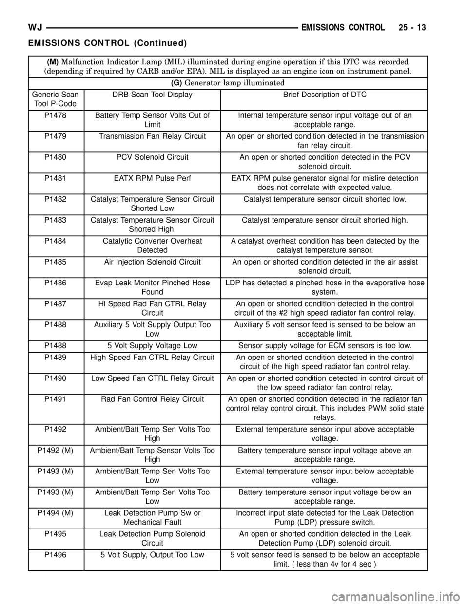
(M)Malfunction Indicator Lamp (MIL) illuminated during engine operation if this DTC was recorded
(depending if required by CARB and/or EPA). MIL is displayed as an engine icon on instrument panel.
(G)Generator lamp illuminated
Generic Scan
Tool P-CodeDRB Scan Tool Display Brief Description of DTC
P1478 Battery Temp Sensor Volts Out of
LimitInternal temperature sensor input voltage out of an
acceptable range.
P1479 Transmission Fan Relay Circuit An open or shorted condition detected in the transmission
fan relay circuit.
P1480 PCV Solenoid Circuit An open or shorted condition detected in the PCV
solenoid circuit.
P1481 EATX RPM Pulse Perf EATX RPM pulse generator signal for misfire detection
does not correlate with expected value.
P1482 Catalyst Temperature Sensor Circuit
Shorted LowCatalyst temperature sensor circuit shorted low.
P1483 Catalyst Temperature Sensor Circuit
Shorted High.Catalyst temperature sensor circuit shorted high.
P1484 Catalytic Converter Overheat
DetectedA catalyst overheat condition has been detected by the
catalyst temperature sensor.
P1485 Air Injection Solenoid Circuit An open or shorted condition detected in the air assist
solenoid circuit.
P1486 Evap Leak Monitor Pinched Hose
FoundLDP has detected a pinched hose in the evaporative hose
system.
P1487 Hi Speed Rad Fan CTRL Relay
CircuitAn open or shorted condition detected in the control
circuit of the #2 high speed radiator fan control relay.
P1488 Auxiliary 5 Volt Supply Output Too
LowAuxiliary 5 volt sensor feed is sensed to be below an
acceptable limit.
P1488 5 Volt Supply Voltage Low Sensor supply voltage for ECM sensors is too low.
P1489 High Speed Fan CTRL Relay Circuit An open or shorted condition detected in the control
circuit of the high speed radiator fan control relay.
P1490 Low Speed Fan CTRL Relay Circuit An open or shorted condition detected in control circuit of
the low speed radiator fan control relay.
P1491 Rad Fan Control Relay Circuit An open or shorted condition detected in the radiator fan
control relay control circuit. This includes PWM solid state
relays.
P1492 Ambient/Batt Temp Sen Volts Too
HighExternal temperature sensor input above acceptable
voltage.
P1492 (M) Ambient/Batt Temp Sensor Volts Too
HighBattery temperature sensor input voltage above an
acceptable range.
P1493 (M) Ambient/Batt Temp Sen Volts Too
LowExternal temperature sensor input below acceptable
voltage.
P1493 (M) Ambient/Batt Temp Sen Volts Too
LowBattery temperature sensor input voltage below an
acceptable range.
P1494 (M) Leak Detection Pump Sw or
Mechanical FaultIncorrect input state detected for the Leak Detection
Pump (LDP) pressure switch.
P1495 Leak Detection Pump Solenoid
CircuitAn open or shorted condition detected in the Leak
Detection Pump (LDP) solenoid circuit.
P1496 5 Volt Supply, Output Too Low 5 volt sensor feed is sensed to be below an acceptable
limit. ( less than 4v for 4 sec )
WJEMISSIONS CONTROL 25 - 13
EMISSIONS CONTROL (Continued)
Page 2169 of 2199
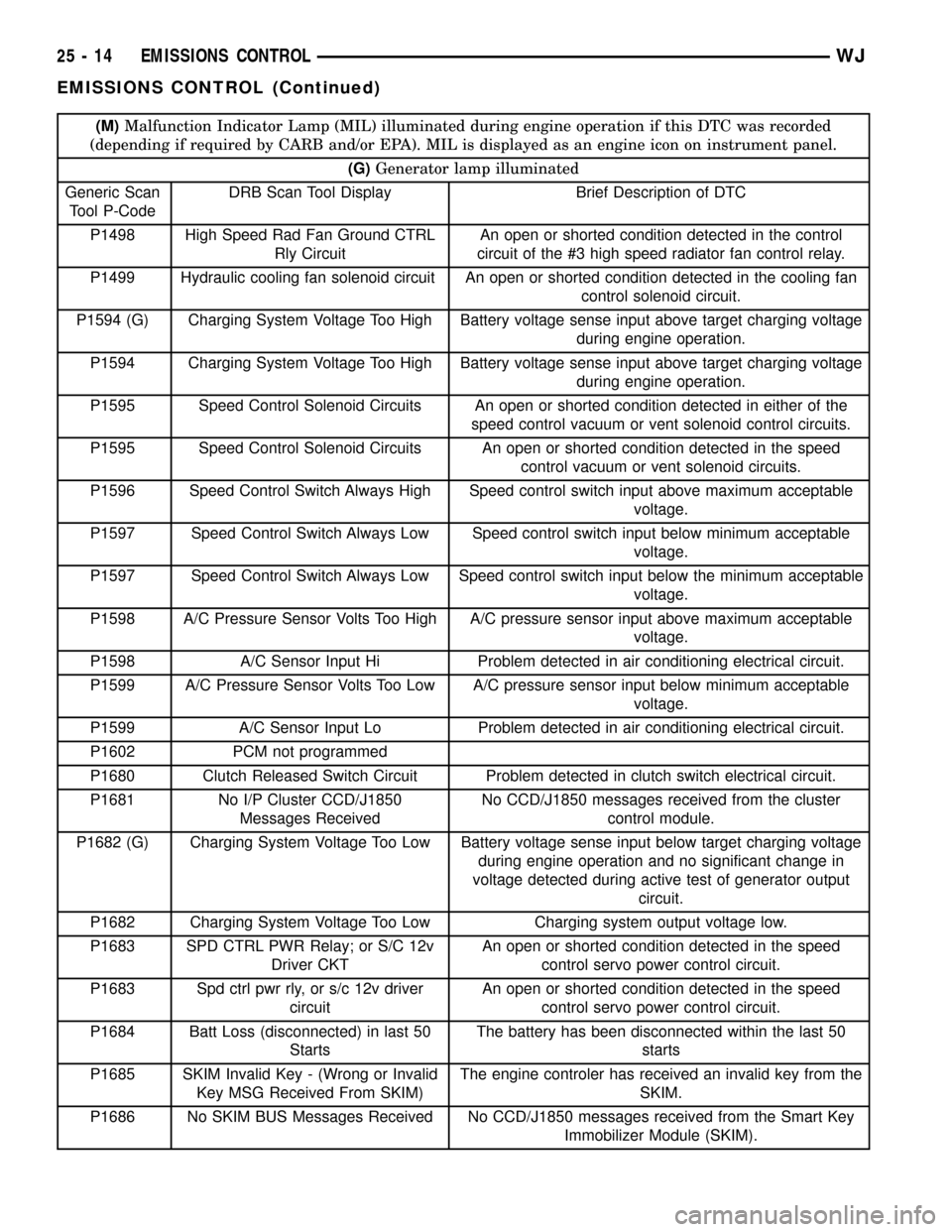
(M)Malfunction Indicator Lamp (MIL) illuminated during engine operation if this DTC was recorded
(depending if required by CARB and/or EPA). MIL is displayed as an engine icon on instrument panel.
(G)Generator lamp illuminated
Generic Scan
Tool P-CodeDRB Scan Tool Display Brief Description of DTC
P1498 High Speed Rad Fan Ground CTRL
Rly CircuitAn open or shorted condition detected in the control
circuit of the #3 high speed radiator fan control relay.
P1499 Hydraulic cooling fan solenoid circuit An open or shorted condition detected in the cooling fan
control solenoid circuit.
P1594 (G) Charging System Voltage Too High Battery voltage sense input above target charging voltage
during engine operation.
P1594 Charging System Voltage Too High Battery voltage sense input above target charging voltage
during engine operation.
P1595 Speed Control Solenoid Circuits An open or shorted condition detected in either of the
speed control vacuum or vent solenoid control circuits.
P1595 Speed Control Solenoid Circuits An open or shorted condition detected in the speed
control vacuum or vent solenoid circuits.
P1596 Speed Control Switch Always High Speed control switch input above maximum acceptable
voltage.
P1597 Speed Control Switch Always Low Speed control switch input below minimum acceptable
voltage.
P1597 Speed Control Switch Always Low Speed control switch input below the minimum acceptable
voltage.
P1598 A/C Pressure Sensor Volts Too High A/C pressure sensor input above maximum acceptable
voltage.
P1598 A/C Sensor Input Hi Problem detected in air conditioning electrical circuit.
P1599 A/C Pressure Sensor Volts Too Low A/C pressure sensor input below minimum acceptable
voltage.
P1599 A/C Sensor Input Lo Problem detected in air conditioning electrical circuit.
P1602 PCM not programmed
P1680 Clutch Released Switch Circuit Problem detected in clutch switch electrical circuit.
P1681 No I/P Cluster CCD/J1850
Messages ReceivedNo CCD/J1850 messages received from the cluster
control module.
P1682 (G) Charging System Voltage Too Low Battery voltage sense input below target charging voltage
during engine operation and no significant change in
voltage detected during active test of generator output
circuit.
P1682 Charging System Voltage Too Low Charging system output voltage low.
P1683 SPD CTRL PWR Relay; or S/C 12v
Driver CKTAn open or shorted condition detected in the speed
control servo power control circuit.
P1683 Spd ctrl pwr rly, or s/c 12v driver
circuitAn open or shorted condition detected in the speed
control servo power control circuit.
P1684 Batt Loss (disconnected) in last 50
StartsThe battery has been disconnected within the last 50
starts
P1685 SKIM Invalid Key - (Wrong or Invalid
Key MSG Received From SKIM)The engine controler has received an invalid key from the
SKIM.
P1686 No SKIM BUS Messages Received No CCD/J1850 messages received from the Smart Key
Immobilizer Module (SKIM).
25 - 14 EMISSIONS CONTROLWJ
EMISSIONS CONTROL (Continued)
Page 2170 of 2199
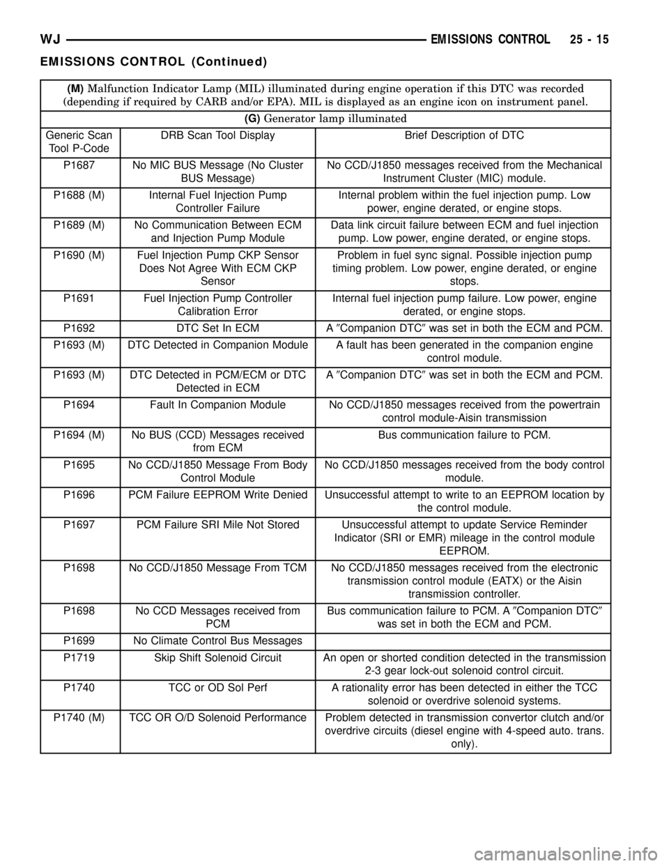
(M)Malfunction Indicator Lamp (MIL) illuminated during engine operation if this DTC was recorded
(depending if required by CARB and/or EPA). MIL is displayed as an engine icon on instrument panel.
(G)Generator lamp illuminated
Generic Scan
Tool P-CodeDRB Scan Tool Display Brief Description of DTC
P1687 No MIC BUS Message (No Cluster
BUS Message)No CCD/J1850 messages received from the Mechanical
Instrument Cluster (MIC) module.
P1688 (M) Internal Fuel Injection Pump
Controller FailureInternal problem within the fuel injection pump. Low
power, engine derated, or engine stops.
P1689 (M) No Communication Between ECM
and Injection Pump ModuleData link circuit failure between ECM and fuel injection
pump. Low power, engine derated, or engine stops.
P1690 (M) Fuel Injection Pump CKP Sensor
Does Not Agree With ECM CKP
SensorProblem in fuel sync signal. Possible injection pump
timing problem. Low power, engine derated, or engine
stops.
P1691 Fuel Injection Pump Controller
Calibration ErrorInternal fuel injection pump failure. Low power, engine
derated, or engine stops.
P1692 DTC Set In ECM A9Companion DTC9was set in both the ECM and PCM.
P1693 (M) DTC Detected in Companion Module A fault has been generated in the companion engine
control module.
P1693 (M) DTC Detected in PCM/ECM or DTC
Detected in ECMA9Companion DTC9was set in both the ECM and PCM.
P1694 Fault In Companion Module No CCD/J1850 messages received from the powertrain
control module-Aisin transmission
P1694 (M) No BUS (CCD) Messages received
from ECMBus communication failure to PCM.
P1695 No CCD/J1850 Message From Body
Control ModuleNo CCD/J1850 messages received from the body control
module.
P1696 PCM Failure EEPROM Write Denied Unsuccessful attempt to write to an EEPROM location by
the control module.
P1697 PCM Failure SRI Mile Not Stored Unsuccessful attempt to update Service Reminder
Indicator (SRI or EMR) mileage in the control module
EEPROM.
P1698 No CCD/J1850 Message From TCM No CCD/J1850 messages received from the electronic
transmission control module (EATX) or the Aisin
transmission controller.
P1698 No CCD Messages received from
PCMBus communication failure to PCM. A9Companion DTC9
was set in both the ECM and PCM.
P1699 No Climate Control Bus Messages
P1719 Skip Shift Solenoid Circuit An open or shorted condition detected in the transmission
2-3 gear lock-out solenoid control circuit.
P1740 TCC or OD Sol Perf A rationality error has been detected in either the TCC
solenoid or overdrive solenoid systems.
P1740 (M) TCC OR O/D Solenoid Performance Problem detected in transmission convertor clutch and/or
overdrive circuits (diesel engine with 4-speed auto. trans.
only).
WJEMISSIONS CONTROL 25 - 15
EMISSIONS CONTROL (Continued)
Page 2171 of 2199
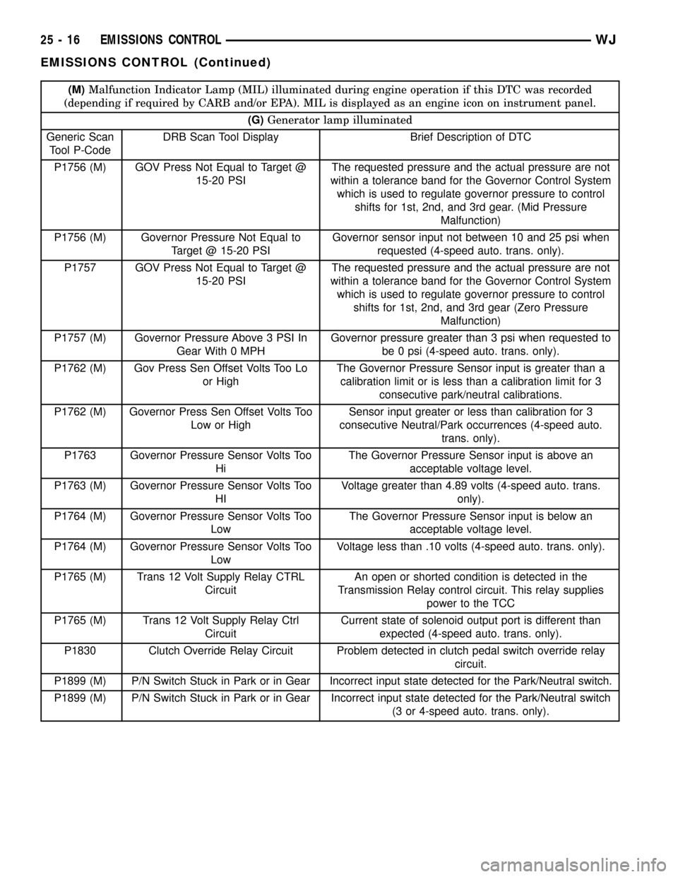
(M)Malfunction Indicator Lamp (MIL) illuminated during engine operation if this DTC was recorded
(depending if required by CARB and/or EPA). MIL is displayed as an engine icon on instrument panel.
(G)Generator lamp illuminated
Generic Scan
Tool P-CodeDRB Scan Tool Display Brief Description of DTC
P1756 (M) GOV Press Not Equal to Target @
15-20 PSIThe requested pressure and the actual pressure are not
within a tolerance band for the Governor Control System
which is used to regulate governor pressure to control
shifts for 1st, 2nd, and 3rd gear. (Mid Pressure
Malfunction)
P1756 (M) Governor Pressure Not Equal to
Target @ 15-20 PSIGovernor sensor input not between 10 and 25 psi when
requested (4-speed auto. trans. only).
P1757 GOV Press Not Equal to Target @
15-20 PSIThe requested pressure and the actual pressure are not
within a tolerance band for the Governor Control System
which is used to regulate governor pressure to control
shifts for 1st, 2nd, and 3rd gear (Zero Pressure
Malfunction)
P1757 (M) Governor Pressure Above 3 PSI In
Gear With 0 MPHGovernor pressure greater than 3 psi when requested to
be 0 psi (4-speed auto. trans. only).
P1762 (M) Gov Press Sen Offset Volts Too Lo
or HighThe Governor Pressure Sensor input is greater than a
calibration limit or is less than a calibration limit for 3
consecutive park/neutral calibrations.
P1762 (M) Governor Press Sen Offset Volts Too
Low or HighSensor input greater or less than calibration for 3
consecutive Neutral/Park occurrences (4-speed auto.
trans. only).
P1763 Governor Pressure Sensor Volts Too
HiThe Governor Pressure Sensor input is above an
acceptable voltage level.
P1763 (M) Governor Pressure Sensor Volts Too
HIVoltage greater than 4.89 volts (4-speed auto. trans.
only).
P1764 (M) Governor Pressure Sensor Volts Too
LowThe Governor Pressure Sensor input is below an
acceptable voltage level.
P1764 (M) Governor Pressure Sensor Volts Too
LowVoltage less than .10 volts (4-speed auto. trans. only).
P1765 (M) Trans 12 Volt Supply Relay CTRL
CircuitAn open or shorted condition is detected in the
Transmission Relay control circuit. This relay supplies
power to the TCC
P1765 (M) Trans 12 Volt Supply Relay Ctrl
CircuitCurrent state of solenoid output port is different than
expected (4-speed auto. trans. only).
P1830 Clutch Override Relay Circuit Problem detected in clutch pedal switch override relay
circuit.
P1899 (M) P/N Switch Stuck in Park or in Gear Incorrect input state detected for the Park/Neutral switch.
P1899 (M) P/N Switch Stuck in Park or in Gear Incorrect input state detected for the Park/Neutral switch
(3 or 4-speed auto. trans. only).
25 - 16 EMISSIONS CONTROLWJ
EMISSIONS CONTROL (Continued)
Page 2190 of 2199

set a temporary fault without turning on the MIL
and continue the leak portion of the test. However,
the PCM will assume that the system is already
pressurized and skip the rapid pump cycles.
Always diagnose leaks, if possible, before discon-
necting connections. Disconnecting connections may
mask a leak condition.
Keep in mind that if the purge solenoid seat is
leaking, it could go undetected since the leak would
end up in the intake manifold. Disconnect the purge
solenoid at the manifold when leak checking. In addi-
tion, a pinched hose fault (P1486) could set if the
purge solenoid does not purge the fuel system prop-
erly (blocked seat). The purge solenoid must vent the
fuel system prior to the LDP system test. If the
purge solenoid cannot properly vent the system the
LDP cannot properly complete the test for P1486 and
this fault can set due to pressure being in the EVAP
system during the test sequence.
Multiple actuation's of the DRB IIItLeak Detec-
tion Pump (LDP) Monitor Test can hide a 0.020 leak
because of excess vapor generation. Additionally, any
source for additional vapor generation can hide a
small leak in the EVAP system. Excess vapor gener-
ation can delay the fall of the LDP diaphragm thus
hiding the small leak. An example of this condition
could be bringing a cold vehicle into a warm shop for
testing or high ambient temperatures.
Fully plugged and partially plugged underhood
vacuum lines have been known to set MIL condi-
tions. P1494 and P0456 can be set for this reason.
Always, thoroughly, check plumbing for pinches or
blockage before condemning components.
TEST EQUIPMENT The Evaporative Emission
Leak Detector (EELD) Miller Special Tool 8404 is
capable of visually detecting leaks in the evaporative
system and will take the place of the ultrasonic leak
detector 6917A. The EELD utilizes shop air and a
smoke generator to visually detect leaks down to
0.020 or smaller. The food grade oil used to make the
smoke includes an UV trace dye that will leave tell-
tale signs of the leak under a black light. This is
helpful when components have to be removed to
determine the exact leak location. For detailed test
instructions, follow the operators manual packaged
with the EELD.
NOTE: Be sure that the PCM has the latest software
update. Reprogram as indicated by any applicable
Technical Service Bulletin. After LDP repairs are
completed, verify the repair by running the DRB IIIT
Leak Detection Pump (LDP) Monitor Test as
described in Technical Service Bulletin 18-12-99.REMOVAL
The Leak Detection Pump (LDP) is located under
the left quarter panel behind the left/rear wheel (Fig.
16). It is attached to a two-piece support bracket
(Fig. 17). The LDP and LDP filter are replaced (ser-
viced) as one unit.
(1) Remove stone shield behind left/rear wheel
(Fig. 18). Drill out plastic rivets for removal.
(2) Remove 3 LDP mounting bolts (Fig. 19).
(3) Remove support bracket brace bolt (Fig. 17).
(4) Loosen, but do not remove 2 support bracket
nuts at frame rail (Fig. 19).
(5) To separate and lower front section of two-piece
support bracket, remove 3 attaching bolts on bottom
of support bracket (Fig. 17). While lowering support
bracket, disconnect LDP wiring clip (Fig. 20).
(6) Disconnect electrical connector at LDP (Fig.
20).
(7) Carefully remove vapor/vacuum lines at LDP
(Fig. 20).
(8) Remove LDP.
INSTALLATION
The LDP is located in the left quarter panel behind
the left/rear wheel. It is attached to a two-piece sup-
port bracket (Fig. 17). The LDP and LDP filter are
replaced (serviced) as one unit.
(1) Position LDP and carefully install vapor/vac-
uum lines to LDP and LDP filter.The vapor/vac-
uum lines and hoses must be firmly connected.
Fig. 16 LOCATION, LDP / EVAP CANISTER
1 - LEAK DETECTION PUMP
2 - EVAP CANISTER
WJEVAPORATIVE EMISSIONS 25 - 35
LEAK DETECTION PUMP (Continued)