Brake line JEEP GRAND CHEROKEE 2003 WJ / 2.G Repair Manual
[x] Cancel search | Manufacturer: JEEP, Model Year: 2003, Model line: GRAND CHEROKEE, Model: JEEP GRAND CHEROKEE 2003 WJ / 2.GPages: 2199, PDF Size: 76.01 MB
Page 1696 of 2199

AUTOMATIC TRANSMISSION - 545RFE
TABLE OF CONTENTS
page page
AUTOMATIC TRANSMISSION - 545RFE
DESCRIPTION........................178
OPERATION..........................179
DIAGNOSIS AND TESTING
DIAGNOSIS AND TESTING - AUTOMATIC
TRANSMISSION.....................179
DIAGNOSIS AND TESTING - PRELIMINARY . 180
DIAGNOSIS AND TESTING - ROAD
TESTING...........................180
DIAGNOSIS AND TESTING - HYDRAULIC
PRESSURE TEST....................181
DIAGNOSIS AND TESTING - AIR CHECKING
TRANSMISSION CLUTCH OPERATION....182
DIAGNOSIS AND TESTING - CONVERTER
HOUSING FLUID LEAK................182
STANDARD PROCEDURE - ALUMINUM
THREAD REPAIR.....................183
REMOVAL............................183
DISASSEMBLY........................185
CLEANING...........................190
INSPECTION.........................190
ASSEMBLY...........................190
INSTALLATION........................197
SCHEMATICS AND DIAGRAMS
HYDRAULIC SCHEMATICS.............199
SPECIFICATIONS
TRANSMISSION.....................220
SPECIAL TOOLS
RFE TRANSMISSION.................221
4C RETAINER/BULKHEAD
DISASSEMBLY........................224
ASSEMBLY...........................224
ADAPTER HOUSING SEAL
REMOVAL............................225
INSTALLATION........................225
BRAKE TRANSMISSION SHIFT INTERLOCK
MECHANISM
DESCRIPTION........................226
OPERATION..........................226
DIAGNOSIS AND TESTING - BRAKE
TRANSMISSION SHIFT INTERLOCK......226
ADJUSTMENTS - BRAKE TRANSMISSION
SHIFT INTERLOCK...................227
FLUID AND FILTER
DIAGNOSIS AND TESTING
DIAGNOSIS AND TESTING - EFFECTS OF
INCORRECT FLUID LEVEL.............228
DIAGNOSIS AND TESTING - CAUSES OF
BURNT FLUID.......................228DIAGNOSIS AND TESTING - FLUID
CONTAMINATION....................228
STANDARD PROCEDURE
STANDARD PROCEDURE - FLUID LEVEL
CHECK............................229
STANDARD PROCEDURE - FLUID AND
FILTER REPLACEMENT...............230
STANDARD PROCEDURE - TRANSMISSION
FILL...............................230
GEARSHIFT CABLE
DIAGNOSIS AND TESTING - GEARSHIFT
CABLE.............................231
REMOVAL............................231
INSTALLATION........................231
ADJUSTMENTS - GEARSHIFT CABLE......232
HOLDING CLUTCHES
DESCRIPTION........................233
OPERATION..........................234
INPUT CLUTCH ASSEMBLY
DESCRIPTION........................235
OPERATION..........................235
DISASSEMBLY........................237
ASSEMBLY...........................238
INPUT SPEED SENSOR
DESCRIPTION........................244
OPERATION..........................244
REMOVAL............................244
INSTALLATION........................244
LINE PRESSURE (LP) SENSOR
DESCRIPTION........................245
OPERATION..........................245
REMOVAL............................245
INSTALLATION........................245
LOW/REVERSE CLUTCH
DISASSEMBLY........................246
CLEANING...........................247
INSPECTION.........................247
ASSEMBLY...........................247
OIL PUMP
DESCRIPTION........................248
OPERATION..........................248
STANDARD PROCEDURE - OIL PUMP
VOLUME CHECK.....................249
DISASSEMBLY........................250
CLEANING...........................252
INSPECTION.........................252
ASSEMBLY...........................253
OIL PUMP FRONT SEAL
REMOVAL............................253
WJAUTOMATIC TRANSMISSION - 545RFE 21 - 177
Page 1747 of 2199

(8) Engine starts must be possible with shifter
lever in PARK or NEUTRAL gate positions only.
Engine starts must not be possible in any other gate
positions other than PARK or NEUTRAL.
(9) With shifter lever handle push-button not
depressed and lever detent in:
²PARK position- apply forward force on center of
handle and remove pressure. Engine start must be
possible.
²PARK position- apply rearward force on center
of handle and remove pressure. Engine start must be
possible.
²NEUTRAL position- engine start must be possi-
ble.
²NEUTRAL position, engine running and brakes
applied- Apply forward force on center of shift han-
dle. Transmission should not be able to shift into
REVERSE detent.
FLUID AND FILTER
DIAGNOSIS AND TESTING
DIAGNOSIS AND TESTING - EFFECTS OF
INCORRECT FLUID LEVEL
A low fluid level allows the pump to take in air
along with the fluid. Air in the fluid will cause fluid
pressures to be low and develop slower than normal.
If the transmission is overfilled, the gears churn the
fluid into foam. This aerates the fluid and causing
the same conditions occurring with a low level. In
either case, air bubbles cause fluid overheating, oxi-
dation and varnish buildup which interferes with
valve and clutch operation. Foaming also causes fluid
expansion which can result in fluid overflow from the
transmission vent or fill tube. Fluid overflow can eas-
ily be mistaken for a leak if inspection is not careful.
DIAGNOSIS AND TESTING - CAUSES OF
BURNT FLUID
Burnt, discolored fluid is a result of overheating
which has three primary causes.
(1) Internal clutch slippage, usually caused by low
line pressure, inadequate clutch apply pressure, or
clutch seal failure.
(2) A result of restricted fluid flow through the
main and/or auxiliary cooler. This condition is usu-
ally the result of a faulty or improperly installed
drainback valve, a damaged main cooler, or severe
restrictions in the coolers and lines caused by debris
or kinked lines.(3) Heavy duty operation with a vehicle not prop-
erly equipped for this type of operation. Trailer tow-
ing or similar high load operation will overheat the
transmission fluid if the vehicle is improperly
equipped. Such vehicles should have an auxiliary
transmission fluid cooler, a heavy duty cooling sys-
tem, and the engine/axle ratio combination needed to
handle heavy loads.
DIAGNOSIS AND TESTING - FLUID
CONTAMINATION
Transmission fluid contamination is generally a
result of:
²adding incorrect fluid
²failure to clean dipstick and fill tube when
checking level
²engine coolant entering the fluid
²internal failure that generates debris
²overheat that generates sludge (fluid break-
down)
²failure to reverse flush cooler and lines after
repair
²failure to replace contaminated converter after
repair
The use of non-recommended fluids can result in
transmission failure. The usual results are erratic
shifts, slippage, abnormal wear and eventual failure
due to fluid breakdown and sludge formation. Avoid
this condition by using recommended fluids only.
The dipstick cap and fill tube should be wiped
clean before checking fluid level. Dirt, grease and
other foreign material on the cap and tube could fall
into the tube if not removed beforehand. Take the
time to wipe the cap and tube clean before withdraw-
ing the dipstick.
Engine coolant in the transmission fluid is gener-
ally caused by a cooler malfunction. The only remedy
is to replace the radiator as the cooler in the radiator
is not a serviceable part. If coolant has circulated
through the transmission, an overhaul is necessary.
The transmission cooler and lines should be
reverse flushed whenever a malfunction generates
sludge and/or debris. The torque converter should
also be replaced at the same time.
Failure to flush the cooler and lines will result in
recontamination. Flushing applies to auxiliary cool-
ers as well. The torque converter should also be
replaced whenever a failure generates sludge and
debris. This is necessary because normal converter
flushing procedures will not remove all contami-
nants.
21 - 228 AUTOMATIC TRANSMISSION - 545RFEWJ
BRAKE TRANSMISSION SHIFT INTERLOCK MECHANISM (Continued)
Page 1860 of 2199

TIRES/WHEELS
TABLE OF CONTENTS
page page
TIRES/WHEELS
DIAGNOSIS AND TESTING - TIRE AND
WHEEL RUNOUT......................1
STANDARD PROCEDURE
STANDARD PROCEDURE - TIRE AND
WHEEL BALANCE......................2
STANDARD PROCEDURE - MATCH
MOUNTING...........................4
STANDARD PROCEDURE - TIRE ROTATION . 5
STANDARD PROCEDURE - WHEEL
INSTALLATION........................5
TIRES
DESCRIPTION
DESCRIPTION - TIRES..................6
DESCRIPTION - RADIAL±PLY TIRES.......6
DESCRIPTION - TIRE INFLATION
PRESSURES..........................6
DESCRIPTION - TIRE PRESSURE FOR
HIGH SPEED..........................7
DESCRIPTION - REPLACEMENT TIRES.....7
DIAGNOSIS AND TESTING
DIAGNOSIS AND TESTING - PRESSURE
GAUGES.............................8
DIAGNOSIS AND TESTING - TREAD WEAR
INDICATORS..........................8
DIAGNOSIS AND TESTING - TIRE WEAR
PATTERNS...........................8
DIAGNOSIS AND TESTING - TIRE NOISE
OR VIBRATION........................8STANDARD PROCEDURE - REPAIRING
LEAKS...............................8
CLEANING.............................9
SPECIFICATIONS
TIRES...............................9
SPECIFICATIONS -.....................9
SPARE TIRE
DESCRIPTION - SPARE / TEMPORARY TIRE . . 10
WHEELS
DESCRIPTION.........................10
DIAGNOSIS AND TESTING - WHEEL
INSPECTION.........................10
STANDARD PROCEDURE - WHEEL
REPLACEMENT.......................10
SPECIFICATIONS
TORQUE CHART......................11
STUDS
REMOVAL.............................11
INSTALLATION.........................11
TIRE PRESSURE MONITORING
DESCRIPTION.........................12
OPERATION...........................12
DIAGNOSIS AND TESTING - TIRE PRESSURE
MONITORING SYSTEM.................12
SENSOR
REMOVAL - TIRE PRESSURE SENSOR/
TRANSMITTER.......................12
INSTALLATION - TIRE PRESSURE SENSOR/
TRANSMITTER.......................13
TIRES/WHEELS
DIAGNOSIS AND TESTING - TIRE AND WHEEL
RUNOUT
Radial runout is the difference between the high
and low points on the tire or wheel (Fig. 1).
Lateral runout is thewobbleof the tire or wheel.
Radial runout of more than 1.5 mm (.060 inch)
measured at the center line of the tread may cause
the vehicle to shake.
Lateral runout of more than 2.0 mm (.080 inch)
measured near the shoulder of the tire may cause the
vehicle to shake.
Sometimes radial runout can be reduced. Relocate
the wheel and tire assembly on the mounting studs
(See Method 1). If this does not reduce runout to an
acceptable level, the tire can be rotated on the wheel.
(See Method 2).
METHOD 1 (RELOCATE WHEEL ON HUB)
(1) Drive vehicle a short distance to eliminate tire
flat spotting from a parked position.
(2) Check wheel bearings and adjust if adjustable
or replace if necessary.
(3) Check the wheel mounting surface.
(4) Relocate wheel on the mounting, two studs
over from the original position.
(5) Tighten wheel nuts until all are properly
torqued, to eliminate brake distortion.
(6) Check radial runout. If still excessive, mark
tire sidewall, wheel, and stud at point of maximum
runout and proceed to Method 2.
METHOD 2 (RELOCATE TIRE ON WHEEL)
NOTE: Rotating the tire on wheel is particularly
effective when there is runout in both tire and
wheel.
WJTIRES/WHEELS 22 - 1
Page 2184 of 2199

INSTALLATION - FIXED ORIFICE FITTING
When installing fixed orifice fitting, be sure loca-
tions of fixed orifice fitting and air inlet fitting (Fig.
9) have not been inadvertently exchanged. The fixed
orifice fitting is light grey in color and is located at
rearof valve cover. The air inlet fitting is black in
color and is located atfrontof valve cover.
(1) Connect fitting to CCV breather tube.
(2) Return fixed orifice fitting to valve cover grom-
met.
EVAP/PURGE SOLENOID
DESCRIPTION
The duty cycle EVAP canister purge solenoid (DCP)
regulates the rate of vapor flow from the EVAP can-
ister to the intake manifold. The Powertrain Control
Module (PCM) operates the solenoid.
OPERATION
During the cold start warm-up period and the hot
start time delay, the PCM does not energize the sole-
noid. When de-energized, no vapors are purged. The
PCM de-energizes the solenoid during open loop oper-
ation.
The engine enters closed loop operation after it
reaches a specified temperature and the time delay
ends. During closed loop operation, the PCM cycles
(energizes and de-energizes) the solenoid 5 or 10
times per second, depending upon operating condi-
tions. The PCM varies the vapor flow rate by chang-
ing solenoid pulse width. Pulse width is the amount
of time that the solenoid is energized. The PCM
adjusts solenoid pulse width based on engine operat-
ing condition.
REMOVAL
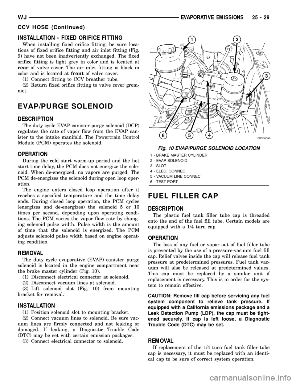
The duty cycle evaporative (EVAP) canister purge
solenoid is located in the engine compartment near
the brake master cylinder (Fig. 10).
(1) Disconnect electrical connector at solenoid.
(2) Disconnect vacuum lines at solenoid.
(3) Lift solenoid slot (Fig. 10) from mounting
bracket for removal.
INSTALLATION
(1) Position solenoid slot to mounting bracket.
(2) Connect vacuum lines to solenoid. Be sure vac-
uum lines are firmly connected and not leaking or
damaged. If leaking, a Diagnostic Trouble Code
(DTC) may be set with certain emission packages.
(3) Connect electrical connector to solenoid.
FUEL FILLER CAP
DESCRIPTION
The plastic fuel tank filler tube cap is threaded
onto the end of the fuel fill tube. Certain models are
equipped with a 1/4 turn cap.
OPERATION
The loss of any fuel or vapor out of fuel filler tube
is prevented by the use of a pressure-vacuum fuel fill
cap. Relief valves inside the cap will release fuel tank
pressure at predetermined pressures. Fuel tank vac-
uum will also be released at predetermined values.
This cap must be replaced by a similar unit if
replacement is necessary. This is in order for the sys-
tem to remain effective.
CAUTION: Remove fill cap before servicing any fuel
system component to relieve tank pressure. If
equipped with a California emissions package and a
Leak Detection Pump (LDP), the cap must be tight-
ened securely. If cap is left loose, a Diagnostic
Trouble Code (DTC) may be set.
REMOVAL
If replacement of the 1/4 turn fuel tank filler tube
cap is necessary, it must be replaced with an identi-
cal cap to be sure of correct system operation.
Fig. 10 EVAP/PURGE SOLENOID LOCATION
1 - BRAKE MASTER CYLINDER
2 - EVAP SOLENOID
3 - SLOT
4 - ELEC. CONNEC.
5 - VACUUM LINE CONNEC.
6 - TEST PORT
WJEVAPORATIVE EMISSIONS 25 - 29
CCV HOSE (Continued)