locks JEEP GRAND CHEROKEE 2003 WJ / 2.G Repair Manual
[x] Cancel search | Manufacturer: JEEP, Model Year: 2003, Model line: GRAND CHEROKEE, Model: JEEP GRAND CHEROKEE 2003 WJ / 2.GPages: 2199, PDF Size: 76.01 MB
Page 906 of 2199
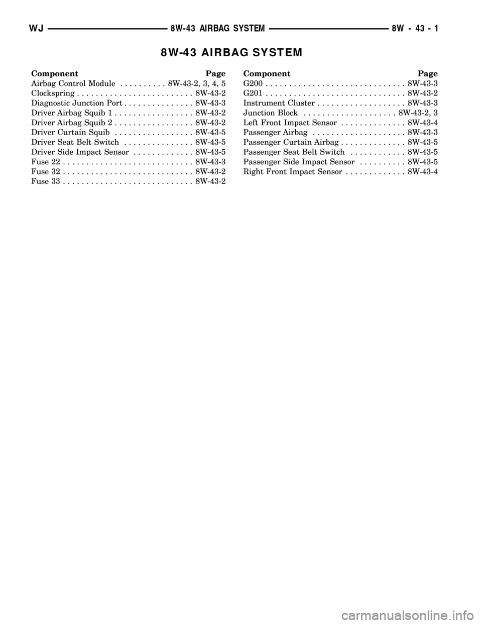
8W-43 AIRBAG SYSTEM
Component Page
Airbag Control Module.......... 8W-43-2, 3, 4, 5
Clockspring......................... 8W-43-2
Diagnostic Junction Port............... 8W-43-3
Driver Airbag Squib 1................. 8W-43-2
Driver Airbag Squib 2................. 8W-43-2
Driver Curtain Squib................. 8W-43-5
Driver Seat Belt Switch............... 8W-43-5
Driver Side Impact Sensor............. 8W-43-5
Fuse 22............................ 8W-43-3
Fuse 32............................ 8W-43-2
Fuse 33............................ 8W-43-2Component Page
G200.............................. 8W-43-3
G201.............................. 8W-43-2
Instrument Cluster................... 8W-43-3
Junction Block.................... 8W-43-2, 3
Left Front Impact Sensor.............. 8W-43-4
Passenger Airbag.................... 8W-43-3
Passenger Curtain Airbag.............. 8W-43-5
Passenger Seat Belt Switch............ 8W-43-5
Passenger Side Impact Sensor.......... 8W-43-5
Right Front Impact Sensor............. 8W-43-4
WJ8W-43 AIRBAG SYSTEM 8W - 43 - 1
Page 922 of 2199
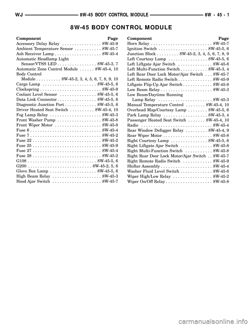
8W-45 BODY CONTROL MODULE
Component Page
Accessory Delay Relay................ 8W-45-9
Ambient Temperature Sensor........... 8W-45-7
Ash Receiver Lamp................... 8W-45-4
Automatic Headlamp Light
Sensor/VTSS LED................ 8W-45-3, 7
Automatic Zone Control Module...... 8W-45-4, 10
Body Control
Module.......... 8W-45-2, 3, 4, 5, 6, 7, 8, 9, 10
Cargo Lamp...................... 8W-45-5, 6
Clockspring......................... 8W-45-9
Coolant Level Sensor............... 8W-45-5, 6
Data Link Connector................ 8W-45-5, 6
Diagnostic Junction Port............. 8W-45-5, 6
Driver Heated Seat Switch.......... 8W-45-4, 10
Fog Lamp Relay..................... 8W-45-3
Front Washer Pump.................. 8W-45-8
Front Wiper Motor................... 8W-45-8
Fuse 6............................. 8W-45-4
Fuse 7............................. 8W-45-2
Fuse 22............................ 8W-45-2
Fuse 25............................ 8W-45-9
Fuse 27............................ 8W-45-4
Fuse 28............................ 8W-45-2
G108............................ 8W-45-5, 6
G200.......................... 8W-45-2, 5, 6
Glove Box Lamp................... 8W-45-5, 6
High Beam Relay.................... 8W-45-3
Hood Ajar Switch.................... 8W-45-7Component Page
Horn Relay......................... 8W-45-7
Ignition Switch.................... 8W-45-5, 6
Junction Block......... 8W-45-2, 3, 4, 5, 6, 7, 8, 9
Left Courtesy Lamp................ 8W-45-5, 6
Left Liftgate Ajar Switch.............. 8W-45-8
Left Multi-Function Switch........... 8W-45-3, 4
Left Rear Door Lock Motor/Ajar Switch . . . 8W-45-7
Left Remote Radio Switch.............. 8W-45-9
Liftgate Flip-Up Ajar Switch............ 8W-45-8
Low Beam Relay..................... 8W-45-3
Low Beam/Daytime Running
Lamp Relay...................... 8W-45-3
Manual Temperature Control........ 8W-45-4, 10
Overhead Map/Courtesy Lamp........ 8W-45-5, 6
Park Lamp Relay.................. 8W-45-3, 4
Passenger Heated Seat Switch....... 8W-45-4, 10
Radio............................. 8W-45-4
Rear Window Defogger Relay......... 8W-45-4, 9
Rear Wiper Motor.................... 8W-45-8
Right Courtesy Lamp............... 8W-45-5, 6
Right Liftgate Ajar Switch............. 8W-45-8
Right Multi-Function Switch........... 8W-45-8
Right Rear Door Lock Motor/Ajar Switch . . 8W-45-7
Right Remote Radio Switch............ 8W-45-9
Shifter Assembly..................... 8W-45-4
Washer Fluid Level Switch............. 8W-45-8
Wiper High/Low Relay................ 8W-45-2
Wiper On/Off Relay................... 8W-45-8
WJ8W-45 BODY CONTROL MODULE 8W - 45 - 1
Page 932 of 2199
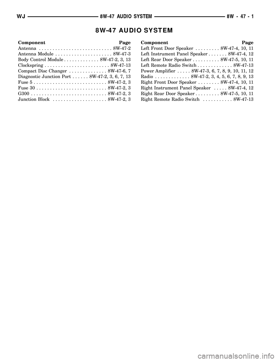
8W-47 AUDIO SYSTEM
Component Page
Antenna........................... 8W-47-2
Antenna Module..................... 8W-47-3
Body Control Module............. 8W-47-2, 3, 13
Clockspring........................ 8W-47-13
Compact Disc Changer.............. 8W-47-6, 7
Diagnostic Junction Port...... 8W-47-2, 3, 6, 7, 13
Fuse 5........................... 8W-47-2, 3
Fuse 30.......................... 8W-47-2, 3
G300............................ 8W-47-2, 3
Junction Block.................... 8W-47-2, 3Component Page
Left Front Door Speaker......... 8W-47-4, 10, 11
Left Instrument Panel Speaker....... 8W-47-4, 12
Left Rear Door Speaker.......... 8W-47-5, 10, 11
Left Remote Radio Switch............. 8W-47-13
Power Amplifier..... 8W-47-3, 6, 7, 8, 9, 10, 11, 12
Radio............. 8W-47-2, 3, 4, 5, 6, 7, 8, 9, 13
Right Front Door Speaker........ 8W-47-4, 10, 11
Right Instrument Panel Speaker..... 8W-47-4, 12
Right Rear Door Speaker......... 8W-47-5, 10, 11
Right Remote Radio Switch........... 8W-47-13
WJ8W-47 AUDIO SYSTEM 8W - 47 - 1
Page 1006 of 2199
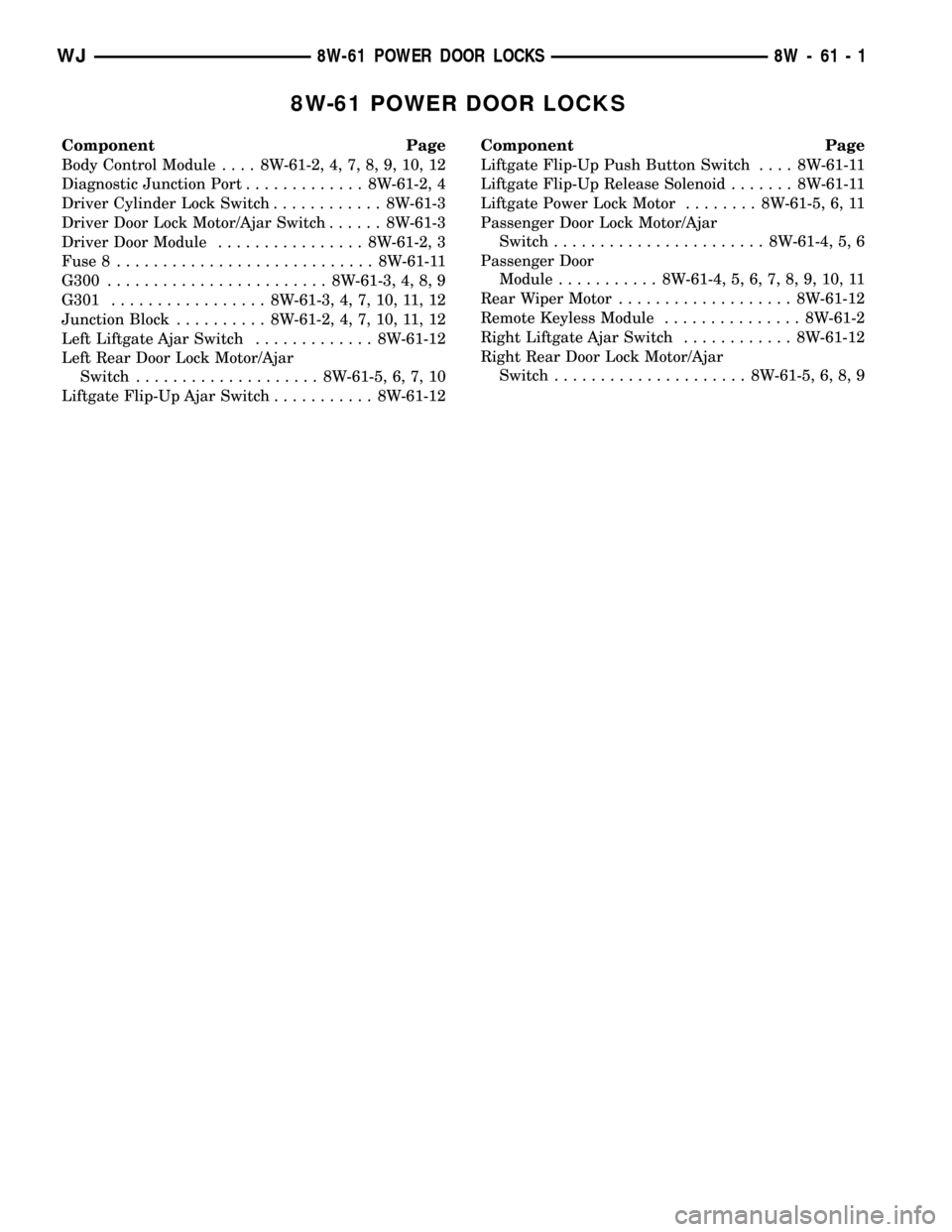
8W-61 POWER DOOR LOCKS
Component Page
Body Control Module.... 8W-61-2, 4, 7, 8, 9, 10, 12
Diagnostic Junction Port............. 8W-61-2, 4
Driver Cylinder Lock Switch............ 8W-61-3
Driver Door Lock Motor/Ajar Switch...... 8W-61-3
Driver Door Module................ 8W-61-2, 3
Fuse 8............................ 8W-61-11
G300........................ 8W-61-3, 4, 8, 9
G301................. 8W-61-3, 4, 7, 10, 11, 12
Junction Block.......... 8W-61-2, 4, 7, 10, 11, 12
Left Liftgate Ajar Switch............. 8W-61-12
Left Rear Door Lock Motor/Ajar
Switch.................... 8W-61-5, 6, 7, 10
Liftgate Flip-Up Ajar Switch........... 8W-61-12Component Page
Liftgate Flip-Up Push Button Switch.... 8W-61-11
Liftgate Flip-Up Release Solenoid....... 8W-61-11
Liftgate Power Lock Motor........ 8W-61-5, 6, 11
Passenger Door Lock Motor/Ajar
Switch....................... 8W-61-4, 5, 6
Passenger Door
Module........... 8W-61-4, 5, 6, 7, 8, 9, 10, 11
Rear Wiper Motor................... 8W-61-12
Remote Keyless Module............... 8W-61-2
Right Liftgate Ajar Switch............ 8W-61-12
Right Rear Door Lock Motor/Ajar
Switch..................... 8W-61-5, 6, 8, 9
WJ8W-61 POWER DOOR LOCKS 8W - 61 - 1
Page 1049 of 2199
Component Page
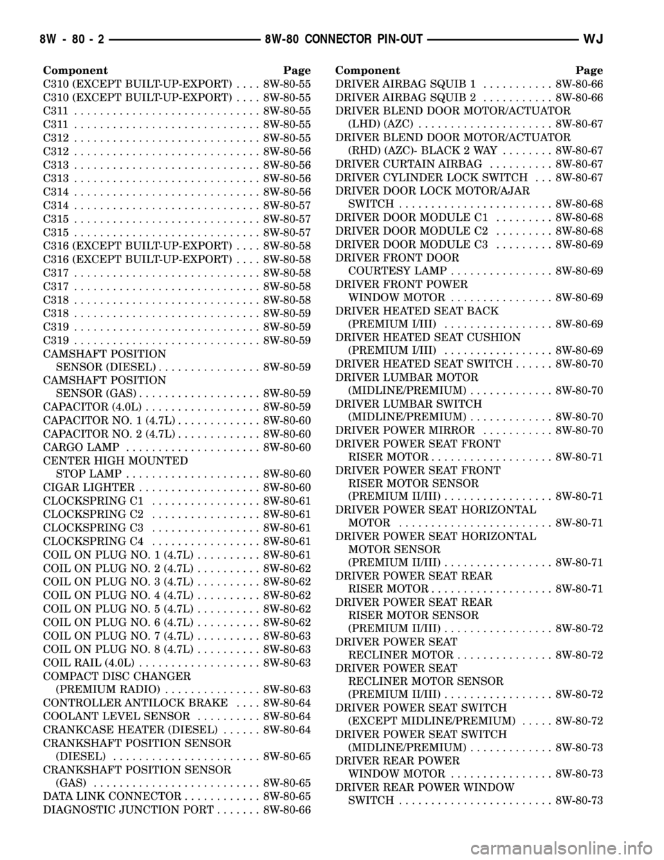
C310 (EXCEPT BUILT-UP-EXPORT).... 8W-80-55
C310 (EXCEPT BUILT-UP-EXPORT).... 8W-80-55
C311 ............................. 8W-80-55
C311 ............................. 8W-80-55
C312............................. 8W-80-55
C312............................. 8W-80-56
C313............................. 8W-80-56
C313............................. 8W-80-56
C314............................. 8W-80-56
C314............................. 8W-80-57
C315............................. 8W-80-57
C315............................. 8W-80-57
C316 (EXCEPT BUILT-UP-EXPORT).... 8W-80-58
C316 (EXCEPT BUILT-UP-EXPORT).... 8W-80-58
C317............................. 8W-80-58
C317............................. 8W-80-58
C318............................. 8W-80-58
C318............................. 8W-80-59
C319............................. 8W-80-59
C319............................. 8W-80-59
CAMSHAFT POSITION
SENSOR (DIESEL)................ 8W-80-59
CAMSHAFT POSITION
SENSOR (GAS)................... 8W-80-59
CAPACITOR (4.0L).................. 8W-80-59
CAPACITOR NO. 1 (4.7L)............. 8W-80-60
CAPACITOR NO. 2 (4.7L)............. 8W-80-60
CARGO LAMP..................... 8W-80-60
CENTER HIGH MOUNTED
STOP LAMP..................... 8W-80-60
CIGAR LIGHTER................... 8W-80-60
CLOCKSPRING C1................. 8W-80-61
CLOCKSPRING C2................. 8W-80-61
CLOCKSPRING C3................. 8W-80-61
CLOCKSPRING C4................. 8W-80-61
COIL ON PLUG NO. 1 (4.7L).......... 8W-80-61
COIL ON PLUG NO. 2 (4.7L).......... 8W-80-62
COIL ON PLUG NO. 3 (4.7L).......... 8W-80-62
COIL ON PLUG NO. 4 (4.7L).......... 8W-80-62
COIL ON PLUG NO. 5 (4.7L).......... 8W-80-62
COIL ON PLUG NO. 6 (4.7L).......... 8W-80-62
COIL ON PLUG NO. 7 (4.7L).......... 8W-80-63
COIL ON PLUG NO. 8 (4.7L).......... 8W-80-63
COIL RAIL (4.0L)................... 8W-80-63
COMPACT DISC CHANGER
(PREMIUM RADIO)............... 8W-80-63
CONTROLLER ANTILOCK BRAKE.... 8W-80-64
COOLANT LEVEL SENSOR.......... 8W-80-64
CRANKCASE HEATER (DIESEL)...... 8W-80-64
CRANKSHAFT POSITION SENSOR
(DIESEL)....................... 8W-80-65
CRANKSHAFT POSITION SENSOR
(GAS).......................... 8W-80-65
DATA LINK CONNECTOR............ 8W-80-65
DIAGNOSTIC JUNCTION PORT....... 8W-80-66Component Page
DRIVER AIRBAG SQUIB 1........... 8W-80-66
DRIVER AIRBAG SQUIB 2........... 8W-80-66
DRIVER BLEND DOOR MOTOR/ACTUATOR
(LHD) (AZC)..................... 8W-80-67
DRIVER BLEND DOOR MOTOR/ACTUATOR
(RHD) (AZC)- BLACK 2 WAY........ 8W-80-67
DRIVER CURTAIN AIRBAG.......... 8W-80-67
DRIVER CYLINDER LOCK SWITCH . . . 8W-80-67
DRIVER DOOR LOCK MOTOR/AJAR
SWITCH........................ 8W-80-68
DRIVER DOOR MODULE C1......... 8W-80-68
DRIVER DOOR MODULE C2......... 8W-80-68
DRIVER DOOR MODULE C3......... 8W-80-69
DRIVER FRONT DOOR
COURTESY LAMP................ 8W-80-69
DRIVER FRONT POWER
WINDOW MOTOR................ 8W-80-69
DRIVER HEATED SEAT BACK
(PREMIUM I/III)................. 8W-80-69
DRIVER HEATED SEAT CUSHION
(PREMIUM I/III)................. 8W-80-69
DRIVER HEATED SEAT SWITCH...... 8W-80-70
DRIVER LUMBAR MOTOR
(MIDLINE/PREMIUM)............. 8W-80-70
DRIVER LUMBAR SWITCH
(MIDLINE/PREMIUM)............. 8W-80-70
DRIVER POWER MIRROR........... 8W-80-70
DRIVER POWER SEAT FRONT
RISER MOTOR................... 8W-80-71
DRIVER POWER SEAT FRONT
RISER MOTOR SENSOR
(PREMIUM II/III)................. 8W-80-71
DRIVER POWER SEAT HORIZONTAL
MOTOR........................ 8W-80-71
DRIVER POWER SEAT HORIZONTAL
MOTOR SENSOR
(PREMIUM II/III)................. 8W-80-71
DRIVER POWER SEAT REAR
RISER MOTOR................... 8W-80-71
DRIVER POWER SEAT REAR
RISER MOTOR SENSOR
(PREMIUM II/III)................. 8W-80-72
DRIVER POWER SEAT
RECLINER MOTOR............... 8W-80-72
DRIVER POWER SEAT
RECLINER MOTOR SENSOR
(PREMIUM II/III)................. 8W-80-72
DRIVER POWER SEAT SWITCH
(EXCEPT MIDLINE/PREMIUM)..... 8W-80-72
DRIVER POWER SEAT SWITCH
(MIDLINE/PREMIUM)............. 8W-80-73
DRIVER REAR POWER
WINDOW MOTOR................ 8W-80-73
DRIVER REAR POWER WINDOW
SWITCH........................ 8W-80-73
8W - 80 - 2 8W-80 CONNECTOR PIN-OUTWJ
Page 1108 of 2199

CLOCKSPRING C1 - BLACK 4 WAY
CAV CIRCUIT FUNCTION
1 X3 20GY/OR HORN RELAY CONTROL
2 V37 20RD/LG SPEED CONTROL SWITCH SIGNAL
3 K4 20BK/LB SENSOR GROUND
4- -
CLOCKSPRING C2-4WAY
CAV CIRCUIT FUNCTION
1 R63 20TN/LB DRIVER SQUIB 2 LINE 2
2 R61 20OR/LB DRIVER SQUIB 2 LINE 1
3 R43 20BK/LB DRIVER SQUIB 1 LINE 1
4 R45 20DG/LB DRIVER SQUIB 1 LINE 2
CLOCKSPRING C3 - GRAY 6 WAY
CAV CIRCUIT FUNCTION
1 X20 20RD/YL RADIO CONTROL MUX
2 X10 20RD/BK RADIO CONTROL MUX RETURN
3 X3 20GY/OR HORN RELAY CONTROL
4 V37 20RD/LG SPEED CONTROL SWITCH SIGNAL
5 K4 20BK/LB SENSOR GROUND
6- -
CLOCKSPRING C4 - BLACK 2 WAY
CAV CIRCUIT FUNCTION
1 X20 20RD/YL RADIO CONTROL MUX
2 X10 20RD/BK RADIO CONTROL MUX RETURN
COIL ON PLUG NO. 1 (4.7L) - BLACK 3 WAY
CAV CIRCUIT FUNCTION
1 K91 14TN/RD COIL DRIVER NO. 1
2 A142 14DG/OR AUTO SHUT DOWN RELAY OUTPUT
3- -
WJ8W-80 CONNECTOR PIN-OUT 8W - 80 - 61
Page 1178 of 2199
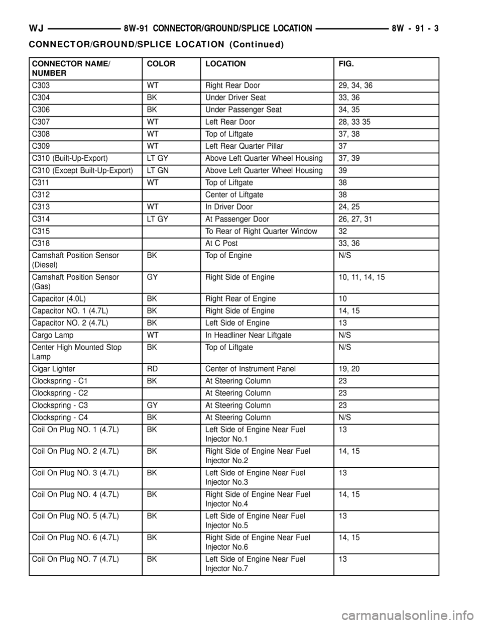
CONNECTOR NAME/
NUMBERCOLOR LOCATION FIG.
C303 WT Right Rear Door 29, 34, 36
C304 BK Under Driver Seat 33, 36
C306 BK Under Passenger Seat 34, 35
C307 WT Left Rear Door 28, 33 35
C308 WT Top of Liftgate 37, 38
C309 WT Left Rear Quarter Pillar 37
C310 (Built-Up-Export) LT GY Above Left Quarter Wheel Housing 37, 39
C310 (Except Built-Up-Export) LT GN Above Left Quarter Wheel Housing 39
C311 WT Top of Liftgate 38
C312 Center of Liftgate 38
C313 WT In Driver Door 24, 25
C314 LT GY At Passenger Door 26, 27, 31
C315 To Rear of Right Quarter Window 32
C318 At C Post 33, 36
Camshaft Position Sensor
(Diesel)BK Top of Engine N/S
Camshaft Position Sensor
(Gas)GY Right Side of Engine 10, 11, 14, 15
Capacitor (4.0L) BK Right Rear of Engine 10
Capacitor NO. 1 (4.7L) BK Right Side of Engine 14, 15
Capacitor NO. 2 (4.7L) BK Left Side of Engine 13
Cargo Lamp WT In Headliner Near Liftgate N/S
Center High Mounted Stop
LampBK Top of Liftgate N/S
Cigar Lighter RD Center of Instrument Panel 19, 20
Clockspring - C1 BK At Steering Column 23
Clockspring - C2 At Steering Column 23
Clockspring - C3 GY At Steering Column 23
Clockspring - C4 BK At Steering Column N/S
Coil On Plug NO. 1 (4.7L) BK Left Side of Engine Near Fuel
Injector No.113
Coil On Plug NO. 2 (4.7L) BK Right Side of Engine Near Fuel
Injector No.214, 15
Coil On Plug NO. 3 (4.7L) BK Left Side of Engine Near Fuel
Injector No.313
Coil On Plug NO. 4 (4.7L) BK Right Side of Engine Near Fuel
Injector No.414, 15
Coil On Plug NO. 5 (4.7L) BK Left Side of Engine Near Fuel
Injector No.513
Coil On Plug NO. 6 (4.7L) BK Right Side of Engine Near Fuel
Injector No.614, 15
Coil On Plug NO. 7 (4.7L) BK Left Side of Engine Near Fuel
Injector No.713
WJ8W-91 CONNECTOR/GROUND/SPLICE LOCATION 8W - 91 - 3
CONNECTOR/GROUND/SPLICE LOCATION (Continued)
Page 1226 of 2199
8W-97 POWER DISTRIBUTION
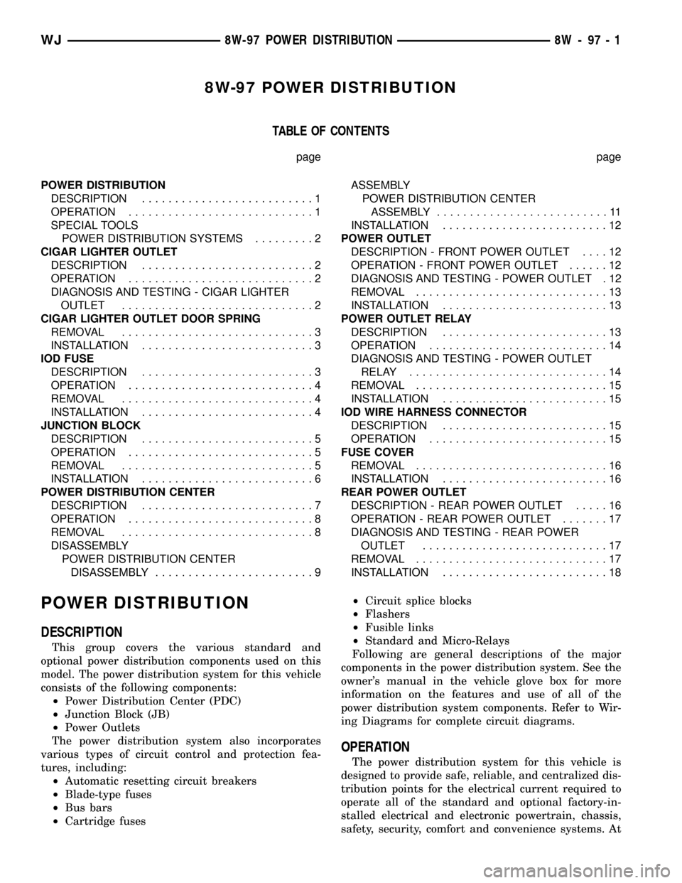
TABLE OF CONTENTS
page page
POWER DISTRIBUTION
DESCRIPTION..........................1
OPERATION............................1
SPECIAL TOOLS
POWER DISTRIBUTION SYSTEMS.........2
CIGAR LIGHTER OUTLET
DESCRIPTION..........................2
OPERATION............................2
DIAGNOSIS AND TESTING - CIGAR LIGHTER
OUTLET.............................2
CIGAR LIGHTER OUTLET DOOR SPRING
REMOVAL.............................3
INSTALLATION..........................3
IOD FUSE
DESCRIPTION..........................3
OPERATION............................4
REMOVAL.............................4
INSTALLATION..........................4
JUNCTION BLOCK
DESCRIPTION..........................5
OPERATION............................5
REMOVAL.............................5
INSTALLATION..........................6
POWER DISTRIBUTION CENTER
DESCRIPTION..........................7
OPERATION............................8
REMOVAL.............................8
DISASSEMBLY
POWER DISTRIBUTION CENTER
DISASSEMBLY........................9ASSEMBLY
POWER DISTRIBUTION CENTER
ASSEMBLY..........................11
INSTALLATION.........................12
POWER OUTLET
DESCRIPTION - FRONT POWER OUTLET....12
OPERATION - FRONT POWER OUTLET......12
DIAGNOSIS AND TESTING - POWER OUTLET . 12
REMOVAL.............................13
INSTALLATION.........................13
POWER OUTLET RELAY
DESCRIPTION.........................13
OPERATION...........................14
DIAGNOSIS AND TESTING - POWER OUTLET
RELAY..............................14
REMOVAL.............................15
INSTALLATION.........................15
IOD WIRE HARNESS CONNECTOR
DESCRIPTION.........................15
OPERATION...........................15
FUSE COVER
REMOVAL.............................16
INSTALLATION.........................16
REAR POWER OUTLET
DESCRIPTION - REAR POWER OUTLET.....16
OPERATION - REAR POWER OUTLET.......17
DIAGNOSIS AND TESTING - REAR POWER
OUTLET............................17
REMOVAL.............................17
INSTALLATION.........................18
POWER DISTRIBUTION
DESCRIPTION
This group covers the various standard and
optional power distribution components used on this
model. The power distribution system for this vehicle
consists of the following components:
²Power Distribution Center (PDC)
²Junction Block (JB)
²Power Outlets
The power distribution system also incorporates
various types of circuit control and protection fea-
tures, including:
²Automatic resetting circuit breakers
²Blade-type fuses
²Bus bars
²Cartridge fuses²Circuit splice blocks
²Flashers
²Fusible links
²Standard and Micro-Relays
Following are general descriptions of the major
components in the power distribution system. See the
owner's manual in the vehicle glove box for more
information on the features and use of all of the
power distribution system components. Refer to Wir-
ing Diagrams for complete circuit diagrams.
OPERATION
The power distribution system for this vehicle is
designed to provide safe, reliable, and centralized dis-
tribution points for the electrical current required to
operate all of the standard and optional factory-in-
stalled electrical and electronic powertrain, chassis,
safety, security, comfort and convenience systems. At
WJ8W-97 POWER DISTRIBUTION 8W - 97 - 1
Page 1266 of 2199
CLEANING
Remove any original sealer from the cover sealing
surface of the engine cylinder head and clean the
surface using a fabric cleaner.
Remove all residue from the sealing surface using
a clean, dry cloth.
INSPECTION
Inspect the engine cylinder head cover for cracks.
Replace the cover, if cracked.
The original dark grey gasket material should
NOT be removed. If sections of the gasket material
are missing or are compressed, replace the engine
cylinder head cover. However, sections with minor
damage such as small cracks, cuts or chips may be
repaired with a hand held applicator. The new mate-
rial must be smoothed over to maintain gasket
height. Allow the gasket material to cure prior to
engine cylinder head cover installation.
INSTALLATION
The cylinder head cover is isolated from the cylin-
der head via grommets and a reusable molded rubber
gasket. The grommet and limiter are retained in the
cylinder head cover.
(1) If a replacement cover is installed, transfer the
CCV valve grommet and oil filler cap from the origi-
nal cover to the replacement cover.
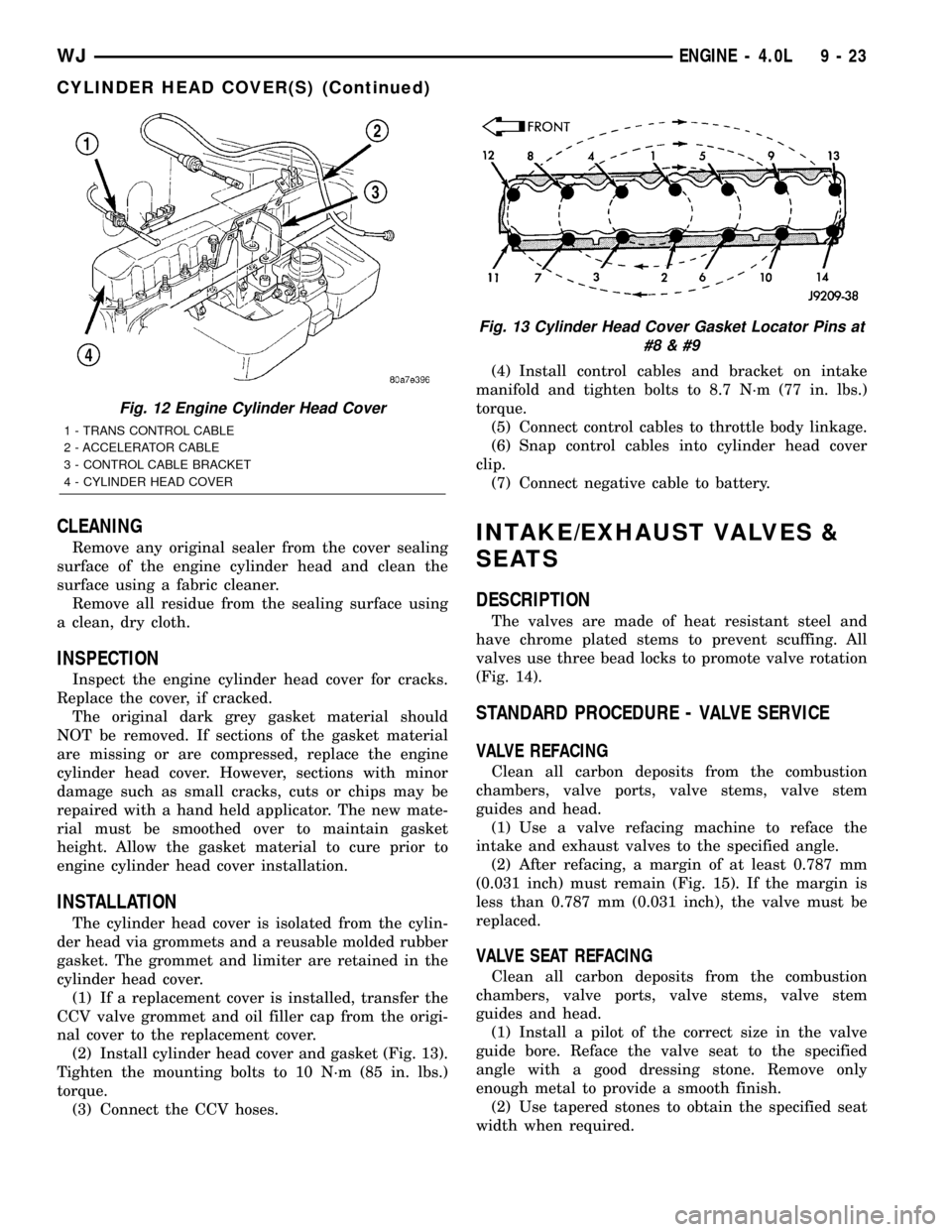
(2) Install cylinder head cover and gasket (Fig. 13).
Tighten the mounting bolts to 10 N´m (85 in. lbs.)
torque.
(3) Connect the CCV hoses.(4) Install control cables and bracket on intake
manifold and tighten bolts to 8.7 N´m (77 in. lbs.)
torque.
(5) Connect control cables to throttle body linkage.
(6) Snap control cables into cylinder head cover
clip.
(7) Connect negative cable to battery.
INTAKE/EXHAUST VALVES &
SEATS
DESCRIPTION
The valves are made of heat resistant steel and
have chrome plated stems to prevent scuffing. All
valves use three bead locks to promote valve rotation
(Fig. 14).
STANDARD PROCEDURE - VALVE SERVICE
VALVE REFACING
Clean all carbon deposits from the combustion
chambers, valve ports, valve stems, valve stem
guides and head.
(1) Use a valve refacing machine to reface the
intake and exhaust valves to the specified angle.
(2) After refacing, a margin of at least 0.787 mm
(0.031 inch) must remain (Fig. 15). If the margin is
less than 0.787 mm (0.031 inch), the valve must be
replaced.
VALVE SEAT REFACING
Clean all carbon deposits from the combustion
chambers, valve ports, valve stems, valve stem
guides and head.
(1) Install a pilot of the correct size in the valve
guide bore. Reface the valve seat to the specified
angle with a good dressing stone. Remove only
enough metal to provide a smooth finish.
(2) Use tapered stones to obtain the specified seat
width when required.
Fig. 12 Engine Cylinder Head Cover
1 - TRANS CONTROL CABLE
2 - ACCELERATOR CABLE
3 - CONTROL CABLE BRACKET
4 - CYLINDER HEAD COVER
Fig. 13 Cylinder Head Cover Gasket Locator Pins at
#8
WJENGINE - 4.0L 9 - 23
CYLINDER HEAD COVER(S) (Continued)
Page 1267 of 2199
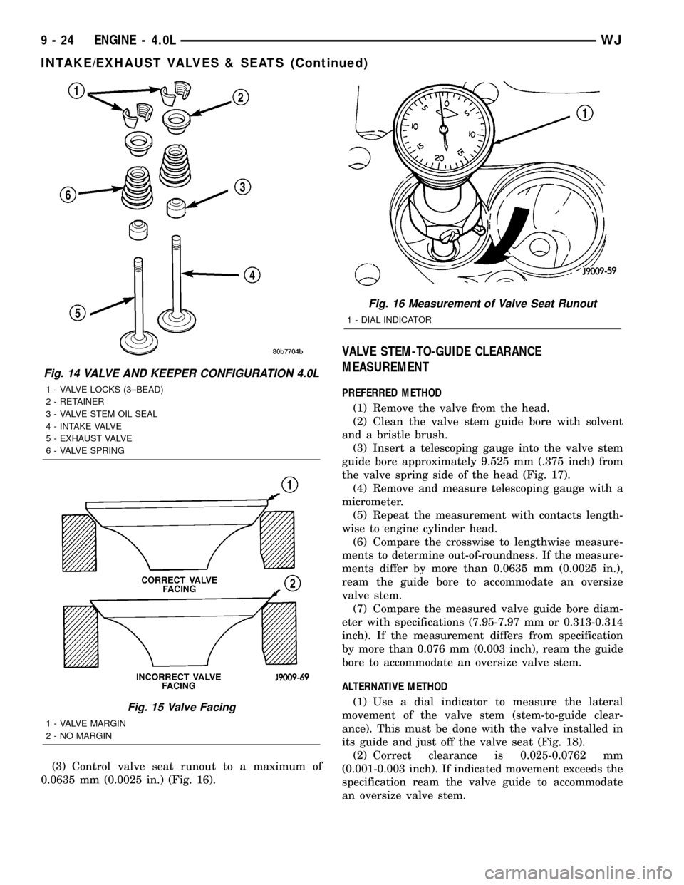
(3) Control valve seat runout to a maximum of
0.0635 mm (0.0025 in.) (Fig. 16).
VALVE STEM-TO-GUIDE CLEARANCE
MEASUREMENT
PREFERRED METHOD
(1) Remove the valve from the head.
(2) Clean the valve stem guide bore with solvent
and a bristle brush.
(3) Insert a telescoping gauge into the valve stem
guide bore approximately 9.525 mm (.375 inch) from
the valve spring side of the head (Fig. 17).
(4) Remove and measure telescoping gauge with a
micrometer.
(5) Repeat the measurement with contacts length-
wise to engine cylinder head.
(6) Compare the crosswise to lengthwise measure-
ments to determine out-of-roundness. If the measure-
ments differ by more than 0.0635 mm (0.0025 in.),
ream the guide bore to accommodate an oversize
valve stem.
(7) Compare the measured valve guide bore diam-
eter with specifications (7.95-7.97 mm or 0.313-0.314
inch). If the measurement differs from specification
by more than 0.076 mm (0.003 inch), ream the guide
bore to accommodate an oversize valve stem.
ALTERNATIVE METHOD
(1) Use a dial indicator to measure the lateral
movement of the valve stem (stem-to-guide clear-
ance). This must be done with the valve installed in
its guide and just off the valve seat (Fig. 18).
(2) Correct clearance is 0.025-0.0762 mm
(0.001-0.003 inch). If indicated movement exceeds the
specification ream the valve guide to accommodate
an oversize valve stem.
Fig. 14 VALVE AND KEEPER CONFIGURATION 4.0L
1 - VALVE LOCKS (3±BEAD)
2 - RETAINER
3 - VALVE STEM OIL SEAL
4 - INTAKE VALVE
5 - EXHAUST VALVE
6 - VALVE SPRING
Fig. 15 Valve Facing
1 - VALVE MARGIN
2 - NO MARGIN
Fig. 16 Measurement of Valve Seat Runout
1 - DIAL INDICATOR
9 - 24 ENGINE - 4.0LWJ
INTAKE/EXHAUST VALVES & SEATS (Continued)