Code JEEP GRAND CHEROKEE 2003 WJ / 2.G Repair Manual
[x] Cancel search | Manufacturer: JEEP, Model Year: 2003, Model line: GRAND CHEROKEE, Model: JEEP GRAND CHEROKEE 2003 WJ / 2.GPages: 2199, PDF Size: 76.01 MB
Page 1246 of 2199
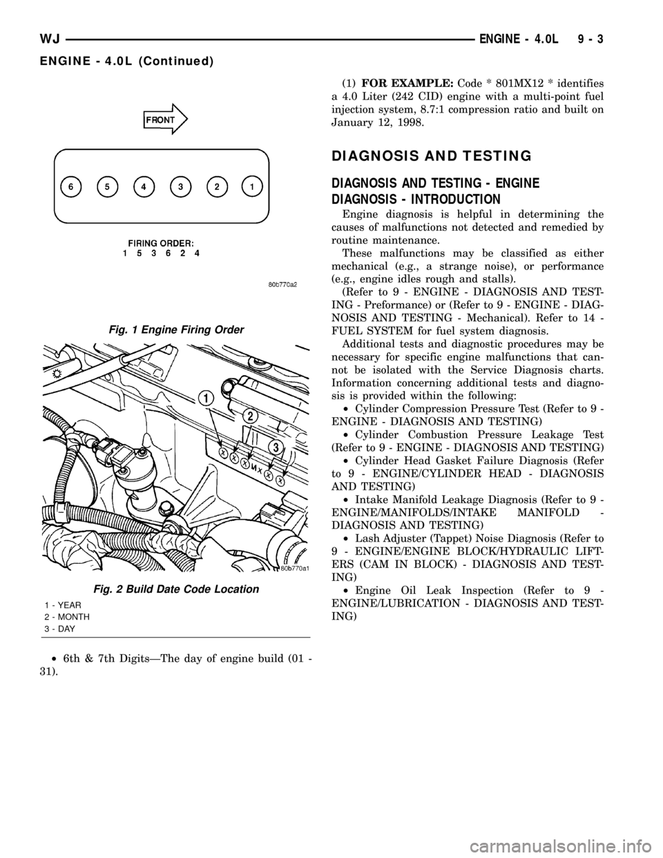
²6th & 7th DigitsÐThe day of engine build (01 -
31).(1)FOR EXAMPLE:Code * 801MX12 * identifies
a 4.0 Liter (242 CID) engine with a multi-point fuel
injection system, 8.7:1 compression ratio and built on
January 12, 1998.
DIAGNOSIS AND TESTING
DIAGNOSIS AND TESTING - ENGINE
DIAGNOSIS - INTRODUCTION
Engine diagnosis is helpful in determining the
causes of malfunctions not detected and remedied by
routine maintenance.
These malfunctions may be classified as either
mechanical (e.g., a strange noise), or performance
(e.g., engine idles rough and stalls).
(Refer to 9 - ENGINE - DIAGNOSIS AND TEST-
ING - Preformance) or (Refer to 9 - ENGINE - DIAG-
NOSIS AND TESTING - Mechanical). Refer to 14 -
FUEL SYSTEM for fuel system diagnosis.
Additional tests and diagnostic procedures may be
necessary for specific engine malfunctions that can-
not be isolated with the Service Diagnosis charts.
Information concerning additional tests and diagno-
sis is provided within the following:
²Cylinder Compression Pressure Test (Refer to 9 -
ENGINE - DIAGNOSIS AND TESTING)
²Cylinder Combustion Pressure Leakage Test
(Refer to 9 - ENGINE - DIAGNOSIS AND TESTING)
²Cylinder Head Gasket Failure Diagnosis (Refer
to 9 - ENGINE/CYLINDER HEAD - DIAGNOSIS
AND TESTING)
²Intake Manifold Leakage Diagnosis (Refer to 9 -
ENGINE/MANIFOLDS/INTAKE MANIFOLD -
DIAGNOSIS AND TESTING)
²Lash Adjuster (Tappet) Noise Diagnosis (Refer to
9 - ENGINE/ENGINE BLOCK/HYDRAULIC LIFT-
ERS (CAM IN BLOCK) - DIAGNOSIS AND TEST-
ING)
²Engine Oil Leak Inspection (Refer to 9 -
ENGINE/LUBRICATION - DIAGNOSIS AND TEST-
ING)
Fig. 1 Engine Firing Order
Fig. 2 Build Date Code Location
1 - YEAR
2 - MONTH
3-DAY
WJENGINE - 4.0L 9 - 3
ENGINE - 4.0L (Continued)
Page 1278 of 2199
is needed to provide the correct clearance. Refer to
CONNECTING ROD BEARING FITTING CHART .
CONNECTING ROD BEARING FITTING CHART
CRANKSHAFT JOURNAL CORRESPONDING ROD BEARING INSERT
Color Code Diameter Upper Insert Size Lower Insert Size
Yellow53.2257 - 53.2079 mm
Yellow - Standard Yellow - Standard
(2.0955 - 2.0948 in.)
Orange53.2079 - 53.1901 mm
Yellow - StandardBlue - Undersize (2.0948 - 2.0941 in.)
0.0178 mm (0.0007 in.) 0.025 mm (0.001 in.)
Undersize
Blue53.1901 - 53.1724 mm
Blue - Undersize Blue - Undersize (2.0941 - 2.0934 in.)
0.0356 mm (0.0014 in.) 0.025 mm (0.001 in.) 0.025 mm (0.001 in.)
Undersize
Red52.9717 - 52.9539 mm
Red - Undersize Red - Undersize (2.0855 - 2.0848 in.)
0.254 mm (0.010 in.) 0.254 mm (0.010 in.) 0.254 mm (0.010 in.)
Undersize
(11)FOR EXAMPLE:If the initial clearance was
0.0762 mm (0.003 inch), 0.025 mm (0.001 inch)
undersize inserts would reduce the clearance by
0.025 mm (0.001 inch). The clearance would be 0.002
inch and within specification. A 0.051 mm (0.002
inch) undersize insert would reduce the initial clear-
ance an additional 0.013 mm (0.0005 inch). The
clearance would then be 0.038 mm (0.0015 inch).
(12) Repeat the Plastigage measurement to verify
your bearing selection prior to final assembly.
(13) Once you have selected the proper insert,
install the insert and cap. Tighten the connecting rod
bolts to 45 N´m (33 ft. lbs.) torque.
SIDE CLEARANCE MEASUREMENT
Slide snug-fitting feeler gauge between the con-
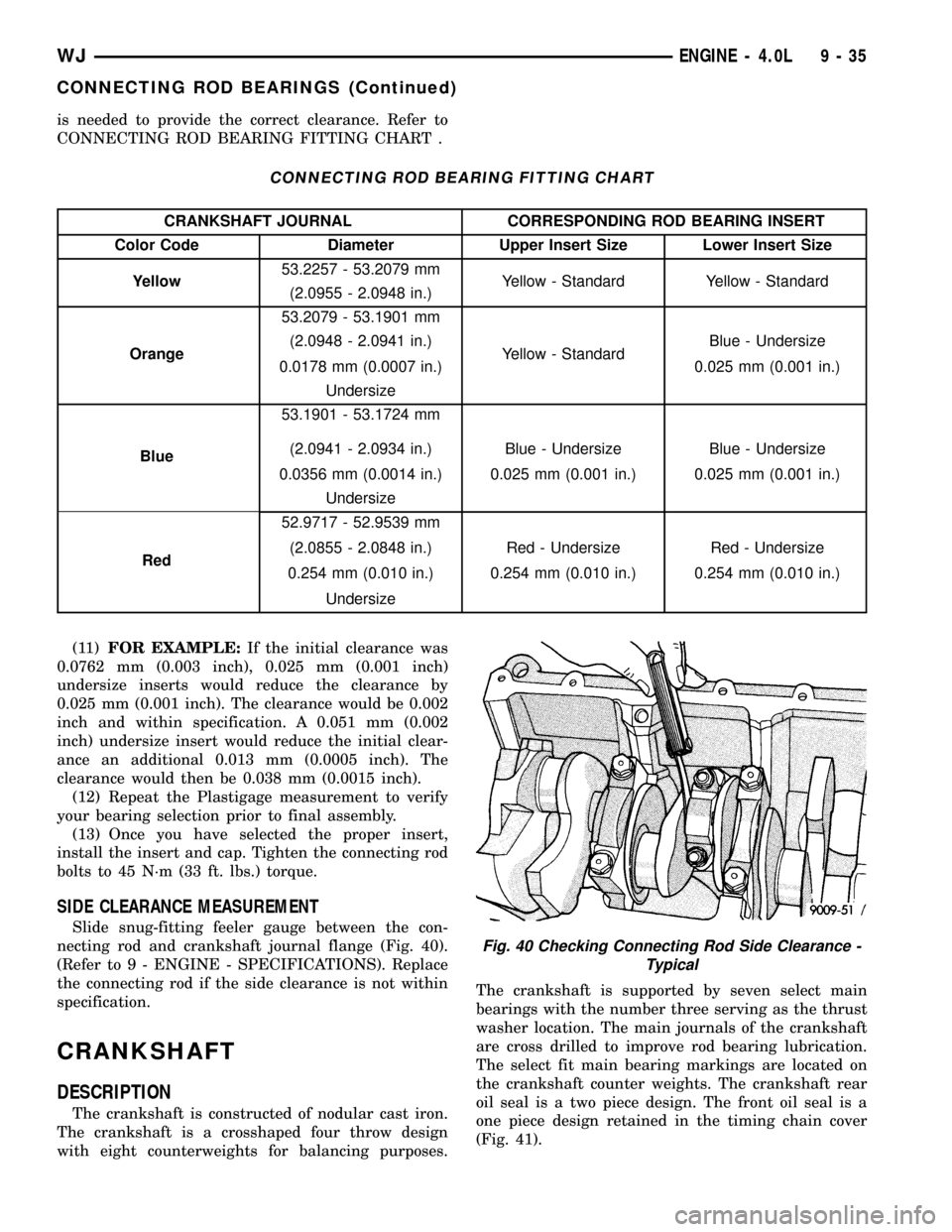
necting rod and crankshaft journal flange (Fig. 40).
(Refer to 9 - ENGINE - SPECIFICATIONS). Replace
the connecting rod if the side clearance is not within
specification.
CRANKSHAFT
DESCRIPTION
The crankshaft is constructed of nodular cast iron.
The crankshaft is a crosshaped four throw design
with eight counterweights for balancing purposes.The crankshaft is supported by seven select main
bearings with the number three serving as the thrust
washer location. The main journals of the crankshaft
are cross drilled to improve rod bearing lubrication.
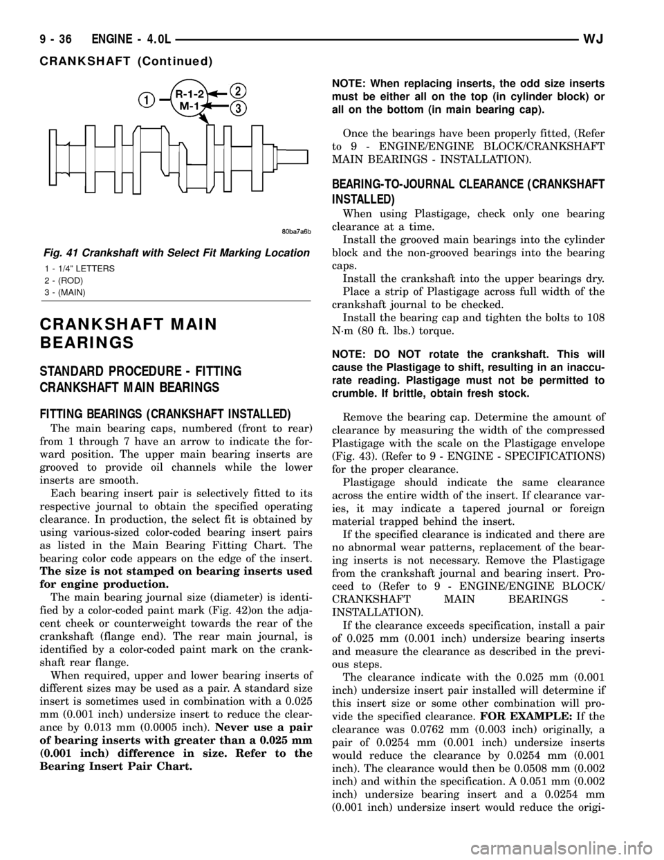
The select fit main bearing markings are located on
the crankshaft counter weights. The crankshaft rear
oil seal is a two piece design. The front oil seal is a
one piece design retained in the timing chain cover
(Fig. 41).
Fig. 40 Checking Connecting Rod Side Clearance -
Typical
WJENGINE - 4.0L 9 - 35
CONNECTING ROD BEARINGS (Continued)
Page 1279 of 2199
CRANKSHAFT MAIN
BEARINGS
STANDARD PROCEDURE - FITTING
CRANKSHAFT MAIN BEARINGS
FITTING BEARINGS (CRANKSHAFT INSTALLED)
The main bearing caps, numbered (front to rear)
from 1 through 7 have an arrow to indicate the for-
ward position. The upper main bearing inserts are
grooved to provide oil channels while the lower
inserts are smooth.
Each bearing insert pair is selectively fitted to its
respective journal to obtain the specified operating
clearance. In production, the select fit is obtained by
using various-sized color-coded bearing insert pairs
as listed in the Main Bearing Fitting Chart. The
bearing color code appears on the edge of the insert.
The size is not stamped on bearing inserts used
for engine production.
The main bearing journal size (diameter) is identi-
fied by a color-coded paint mark (Fig. 42)on the adja-
cent cheek or counterweight towards the rear of the
crankshaft (flange end). The rear main journal, is
identified by a color-coded paint mark on the crank-
shaft rear flange.
When required, upper and lower bearing inserts of
different sizes may be used as a pair. A standard size
insert is sometimes used in combination with a 0.025
mm (0.001 inch) undersize insert to reduce the clear-
ance by 0.013 mm (0.0005 inch).Never use a pair
of bearing inserts with greater than a 0.025 mm
(0.001 inch) difference in size. Refer to the
Bearing Insert Pair Chart.NOTE: When replacing inserts, the odd size inserts
must be either all on the top (in cylinder block) or
all on the bottom (in main bearing cap).
Once the bearings have been properly fitted, (Refer
to 9 - ENGINE/ENGINE BLOCK/CRANKSHAFT
MAIN BEARINGS - INSTALLATION).
BEARING-TO-JOURNAL CLEARANCE (CRANKSHAFT
INSTALLED)
When using Plastigage, check only one bearing
clearance at a time.
Install the grooved main bearings into the cylinder
block and the non-grooved bearings into the bearing
caps.
Install the crankshaft into the upper bearings dry.
Place a strip of Plastigage across full width of the
crankshaft journal to be checked.
Install the bearing cap and tighten the bolts to 108
N´m (80 ft. lbs.) torque.
NOTE: DO NOT rotate the crankshaft. This will
cause the Plastigage to shift, resulting in an inaccu-
rate reading. Plastigage must not be permitted to
crumble. If brittle, obtain fresh stock.
Remove the bearing cap. Determine the amount of
clearance by measuring the width of the compressed
Plastigage with the scale on the Plastigage envelope
(Fig. 43). (Refer to 9 - ENGINE - SPECIFICATIONS)
for the proper clearance.
Plastigage should indicate the same clearance
across the entire width of the insert. If clearance var-
ies, it may indicate a tapered journal or foreign
material trapped behind the insert.
If the specified clearance is indicated and there are
no abnormal wear patterns, replacement of the bear-
ing inserts is not necessary. Remove the Plastigage
from the crankshaft journal and bearing insert. Pro-
ceed to (Refer to 9 - ENGINE/ENGINE BLOCK/
CRANKSHAFT MAIN BEARINGS -
INSTALLATION).
If the clearance exceeds specification, install a pair
of 0.025 mm (0.001 inch) undersize bearing inserts
and measure the clearance as described in the previ-
ous steps.
The clearance indicate with the 0.025 mm (0.001
inch) undersize insert pair installed will determine if
this insert size or some other combination will pro-
vide the specified clearance.FOR EXAMPLE:If the
clearance was 0.0762 mm (0.003 inch) originally, a
pair of 0.0254 mm (0.001 inch) undersize inserts
would reduce the clearance by 0.0254 mm (0.001
inch). The clearance would then be 0.0508 mm (0.002
inch) and within the specification. A 0.051 mm (0.002
inch) undersize bearing insert and a 0.0254 mm
(0.001 inch) undersize insert would reduce the origi-
Fig. 41 Crankshaft with Select Fit Marking Location
1 - 1/4º LETTERS
2 - (ROD)
3 - (MAIN)
9 - 36 ENGINE - 4.0LWJ
CRANKSHAFT (Continued)
Page 1281 of 2199
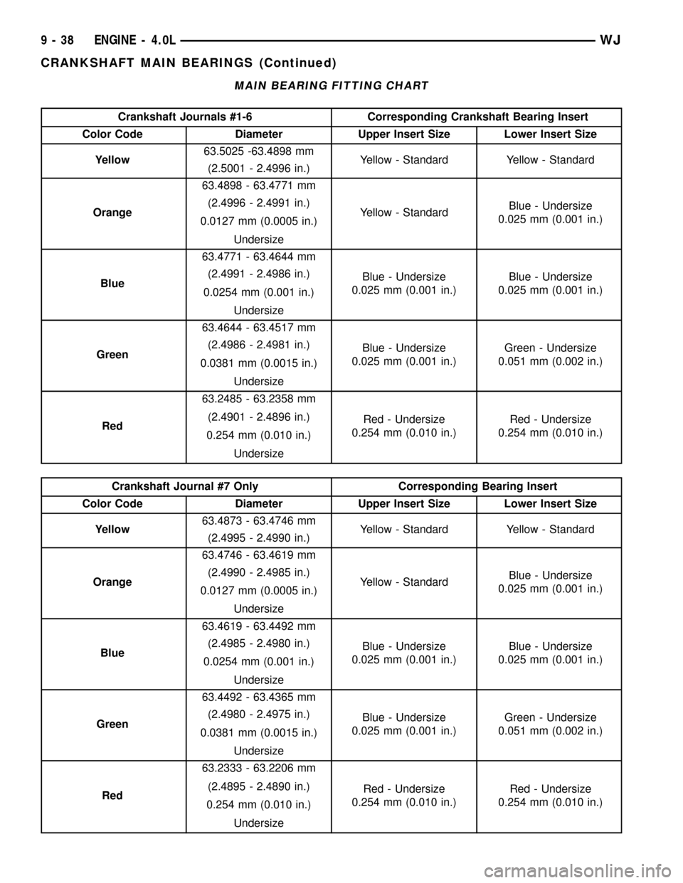
MAIN BEARING FITTING CHART
Crankshaft Journals #1-6 Corresponding Crankshaft Bearing Insert
Color Code Diameter Upper Insert Size Lower Insert Size
Yellow63.5025 -63.4898 mm
Yellow - Standard Yellow - Standard
(2.5001 - 2.4996 in.)
Orange63.4898 - 63.4771 mm
Yellow - StandardBlue - Undersize
0.025 mm (0.001 in.) (2.4996 - 2.4991 in.)
0.0127 mm (0.0005 in.)
Undersize
Blue63.4771 - 63.4644 mm
Blue - Undersize
0.025 mm (0.001 in.)Blue - Undersize
0.025 mm (0.001 in.) (2.4991 - 2.4986 in.)
0.0254 mm (0.001 in.)
Undersize
Green63.4644 - 63.4517 mm
Blue - Undersize
0.025 mm (0.001 in.)Green - Undersize
0.051 mm (0.002 in.) (2.4986 - 2.4981 in.)
0.0381 mm (0.0015 in.)
Undersize
Red63.2485 - 63.2358 mm
Red - Undersize
0.254 mm (0.010 in.)Red - Undersize
0.254 mm (0.010 in.) (2.4901 - 2.4896 in.)
0.254 mm (0.010 in.)
Undersize
Crankshaft Journal #7 Only Corresponding Bearing Insert
Color Code Diameter Upper Insert Size Lower Insert Size
Yellow63.4873 - 63.4746 mm
Yellow - Standard Yellow - Standard
(2.4995 - 2.4990 in.)
Orange63.4746 - 63.4619 mm
Yellow - StandardBlue - Undersize
0.025 mm (0.001 in.) (2.4990 - 2.4985 in.)
0.0127 mm (0.0005 in.)
Undersize
Blue63.4619 - 63.4492 mm
Blue - Undersize
0.025 mm (0.001 in.)Blue - Undersize
0.025 mm (0.001 in.) (2.4985 - 2.4980 in.)
0.0254 mm (0.001 in.)
Undersize
Green63.4492 - 63.4365 mm
Blue - Undersize
0.025 mm (0.001 in.)Green - Undersize
0.051 mm (0.002 in.) (2.4980 - 2.4975 in.)
0.0381 mm (0.0015 in.)
Undersize
Red63.2333 - 63.2206 mm
Red - Undersize
0.254 mm (0.010 in.)Red - Undersize
0.254 mm (0.010 in.) (2.4895 - 2.4890 in.)
0.254 mm (0.010 in.)
Undersize
9 - 38 ENGINE - 4.0LWJ
CRANKSHAFT MAIN BEARINGS (Continued)
Page 1289 of 2199
(11) Lower the vehicle until it is about 2 feet from
the floor.
CAUTION: Ensure that the connecting rod bolts DO
NOT scratch the crankshaft journals or cylinder
walls. Short pieces of rubber hose, slipped over the
rod bolts will provide protection during removal.
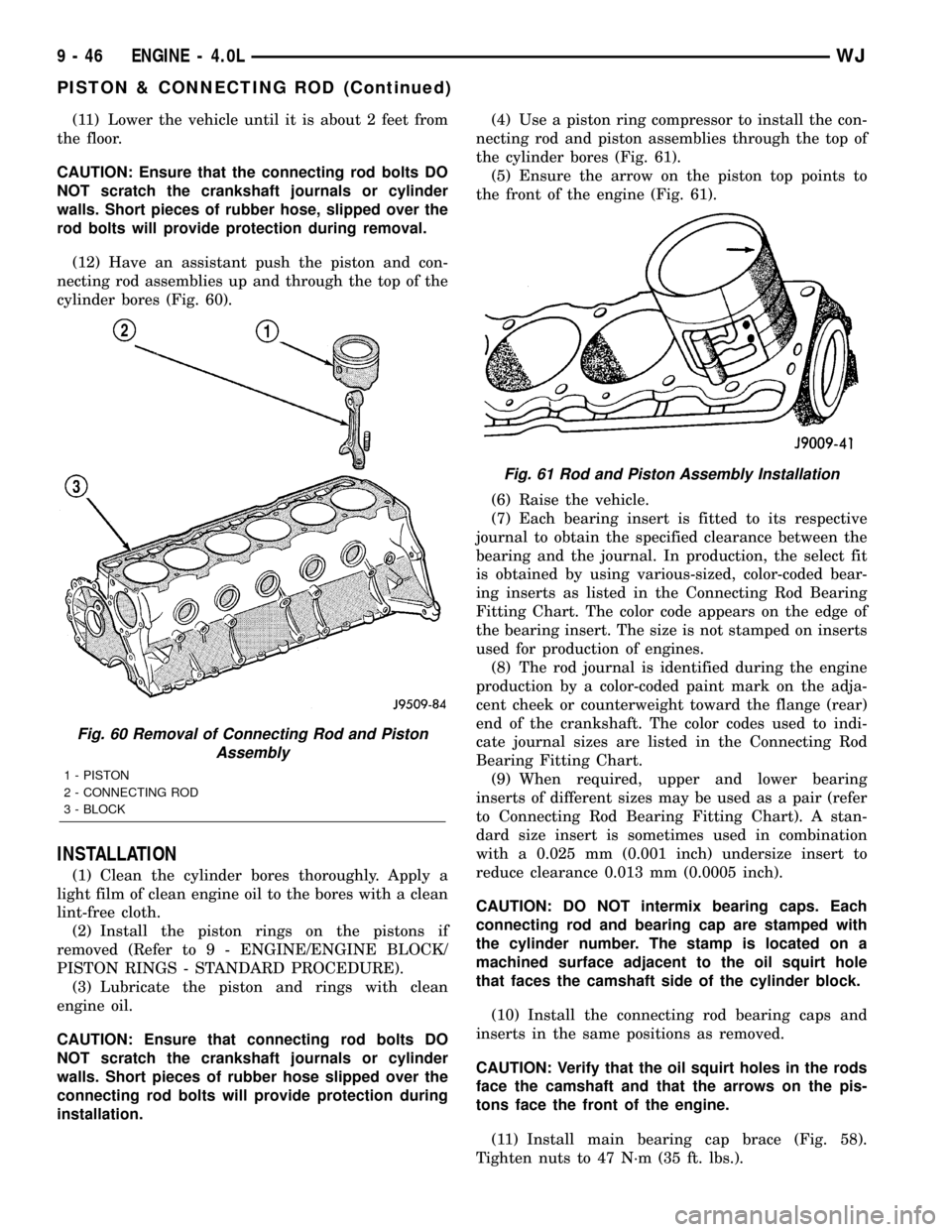
(12) Have an assistant push the piston and con-
necting rod assemblies up and through the top of the
cylinder bores (Fig. 60).
INSTALLATION
(1) Clean the cylinder bores thoroughly. Apply a
light film of clean engine oil to the bores with a clean
lint-free cloth.
(2) Install the piston rings on the pistons if
removed (Refer to 9 - ENGINE/ENGINE BLOCK/
PISTON RINGS - STANDARD PROCEDURE).
(3) Lubricate the piston and rings with clean
engine oil.
CAUTION: Ensure that connecting rod bolts DO
NOT scratch the crankshaft journals or cylinder
walls. Short pieces of rubber hose slipped over the
connecting rod bolts will provide protection during
installation.(4) Use a piston ring compressor to install the con-
necting rod and piston assemblies through the top of
the cylinder bores (Fig. 61).
(5) Ensure the arrow on the piston top points to
the front of the engine (Fig. 61).
(6) Raise the vehicle.
(7) Each bearing insert is fitted to its respective
journal to obtain the specified clearance between the
bearing and the journal. In production, the select fit
is obtained by using various-sized, color-coded bear-
ing inserts as listed in the Connecting Rod Bearing
Fitting Chart. The color code appears on the edge of
the bearing insert. The size is not stamped on inserts
used for production of engines.
(8) The rod journal is identified during the engine
production by a color-coded paint mark on the adja-
cent cheek or counterweight toward the flange (rear)
end of the crankshaft. The color codes used to indi-
cate journal sizes are listed in the Connecting Rod
Bearing Fitting Chart.
(9) When required, upper and lower bearing
inserts of different sizes may be used as a pair (refer
to Connecting Rod Bearing Fitting Chart). A stan-
dard size insert is sometimes used in combination
with a 0.025 mm (0.001 inch) undersize insert to
reduce clearance 0.013 mm (0.0005 inch).
CAUTION: DO NOT intermix bearing caps. Each
connecting rod and bearing cap are stamped with
the cylinder number. The stamp is located on a
machined surface adjacent to the oil squirt hole
that faces the camshaft side of the cylinder block.
(10) Install the connecting rod bearing caps and
inserts in the same positions as removed.
CAUTION: Verify that the oil squirt holes in the rods
face the camshaft and that the arrows on the pis-
tons face the front of the engine.
(11) Install main bearing cap brace (Fig. 58).
Tighten nuts to 47 N´m (35 ft. lbs.).
Fig. 60 Removal of Connecting Rod and Piston
Assembly
1 - PISTON
2 - CONNECTING ROD
3 - BLOCK
Fig. 61 Rod and Piston Assembly Installation
9 - 46 ENGINE - 4.0LWJ
PISTON & CONNECTING ROD (Continued)
Page 1358 of 2199
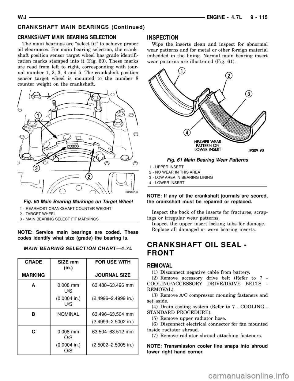
CRANKSHAFT MAIN BEARING SELECTION
The main bearings are ªselect fitº to achieve proper
oil clearances. For main bearing selection, the crank-
shaft position sensor target wheel has grade identifi-
cation marks stamped into it (Fig. 60). These marks
are read from left to right, corresponding with jour-
nal number 1, 2, 3, 4 and 5. The crankshaft position
sensor target wheel is mounted to the number 8
counter weight on the crankshaft.
NOTE: Service main bearings are coded. These
codes identify what size (grade) the bearing is.
MAIN BEARING SELECTION CHARTÐ4.7L
GRADE SIZE mm
(in.)FOR USE WITH
MARKING JOURNAL SIZE
A0.008 mm
U/S63.488±63.496 mm
(0.0004 in.)
U/S(2.4996±2.4999 in.)
BNOMINAL 63.496±63.504 mm
(2.4999±2.5002 in.)
C0.008 mm
O/S63.504±63.512 mm
(0.0004 in.)
O/S(2.5002±2.5005 in.)
INSPECTION
Wipe the inserts clean and inspect for abnormal
wear patterns and for metal or other foreign material
imbedded in the lining. Normal main bearing insert
wear patterns are illustrated (Fig. 61).
NOTE: If any of the crankshaft journals are scored,
the crankshaft must be repaired or replaced.
Inspect the back of the inserts for fractures, scrap-
ings or irregular wear patterns.
Inspect the upper insert locking tabs for damage.
Replace all damaged or worn bearing inserts.
CRANKSHAFT OIL SEAL -
FRONT
REMOVAL
(1) Disconnect negative cable from battery.
(2) Remove accessory drive belt (Refer to 7 -
COOLING/ACCESSORY DRIVE/DRIVE BELTS -
REMOVAL).
(3) Remove A/C compressor mouning fasteners and
set aside.
(4) Drain cooling system (Refer to 7 - COOLING -
STANDARD PROCEDURE).
(5) Remove upper radiator hose.
(6) Disconnect electrical connector for fan mounted
inside radiator shroud.
(7) Remove radiator shroud attaching fasteners.
NOTE: Transmission cooler line snaps into shroud
lower right hand corner.
Fig. 60 Main Bearing Markings on Target Wheel
1 - REARMOST CRANKSHAFT COUNTER WEIGHT
2 - TARGET WHEEL
3 - MAIN BEARING SELECT FIT MARKINGS
Fig. 61 Main Bearing Wear Patterns
1 - UPPER INSERT
2 - NO WEAR IN THIS AREA
3 - LOW AREA IN BEARING LINING
4 - LOWER INSERT
WJENGINE - 4.7L 9 - 115
CRANKSHAFT MAIN BEARINGS (Continued)
Page 1423 of 2199
STANDARD PROCEDURE - FUEL SYSTEM
PRESSURE RELEASE
Use following procedure if the fuel injector
rail is, or is not equipped with a fuel pressure
test port.
(1) Remove fuel fill cap.
(2) Remove fuel pump relay from Power Distribu-
tion Center (PDC). For location of relay, refer to label
on underside of PDC cover.
(3) Start and run engine until it stalls.
(4) Attempt restarting engine until it will no
longer run.
(5) Turn ignition key to OFF position.
CAUTION: Steps 1, 2, 3 and 4 must be performed to
relieve high pressure fuel from within fuel rail. Do
not attempt to use following steps to relieve this
pressure as excessive fuel will be forced into a cyl-
inder chamber.
(6) Unplug connector from any fuel injector.
(7) Attach one end of a jumper wire with alligator
clips (18 gauge or smaller) to either injector terminal.(8) Connect other end of jumper wire to positive
side of battery.
(9) Connect one end of a second jumper wire to
remaining injector terminal.
CAUTION: Powering an injector for more than a few
seconds will permanently damage the injector.
(10) Momentarily touch other end of jumper wire
to negative terminal of battery for no more than a
few seconds.
(11) Place a rag or towel below fuel line quick-con-
nect fitting at fuel rail.
(12) Disconnect quick-connect fitting at fuel rail.
Refer to Quick-Connect Fittings.
(13) Return fuel pump relay to PDC.
(14) One or more Diagnostic Trouble Codes (DTC's)
may have been stored in PCM memory due to fuel
pump relay removal. The DRBtscan tool must be
used to erase a DTC.
SPECIFICATIONS
FUEL SYSTEM PRESSURE
339 kPa 34 kPa (49.2 psi 5 psi).
TORQUE - FUEL DELIVERY
DESCRIPTION N-m Ft. Lbs. In. Lbs.
Accelerator Pedal Bracket Mounting Nuts
(without adjustable pedals)12 2 - 105 20
Fuel Filter/Fuel Press. Reg. Bolts 3 - 26
Fuel Hose Clamps 3 - 26
Fuel Injector Rail Mounting Bolts -4.0L Engine 11 - 100
Fuel Injector Rail Mounting Bolts -4.7L V-8
Engine11 - 100
Fuel Pump Module Locknut 74 55 -
Fuel Tank Filler Tube-to-Body Mounting Bolts 2 - 15
Fuel Tank-to-Body Mounting Bolts 88 65 -
Fuel Tank Support Bracket Bolts (large brackets) 88 65 -
Fuel Tank Support Bracket Bolts (small bracket) 5 - 45
Fuel Tank Support Bracket Nuts (large brackets) 61 45 -
Fuel Tank Heat Shield Nuts (shield-to-tank) 9 - 85
Fuel Tank Heat Shield Nuts (shield-to-body) 3 - 25
14 - 4 FUEL DELIVERYWJ
FUEL DELIVERY (Continued)
Page 1426 of 2199
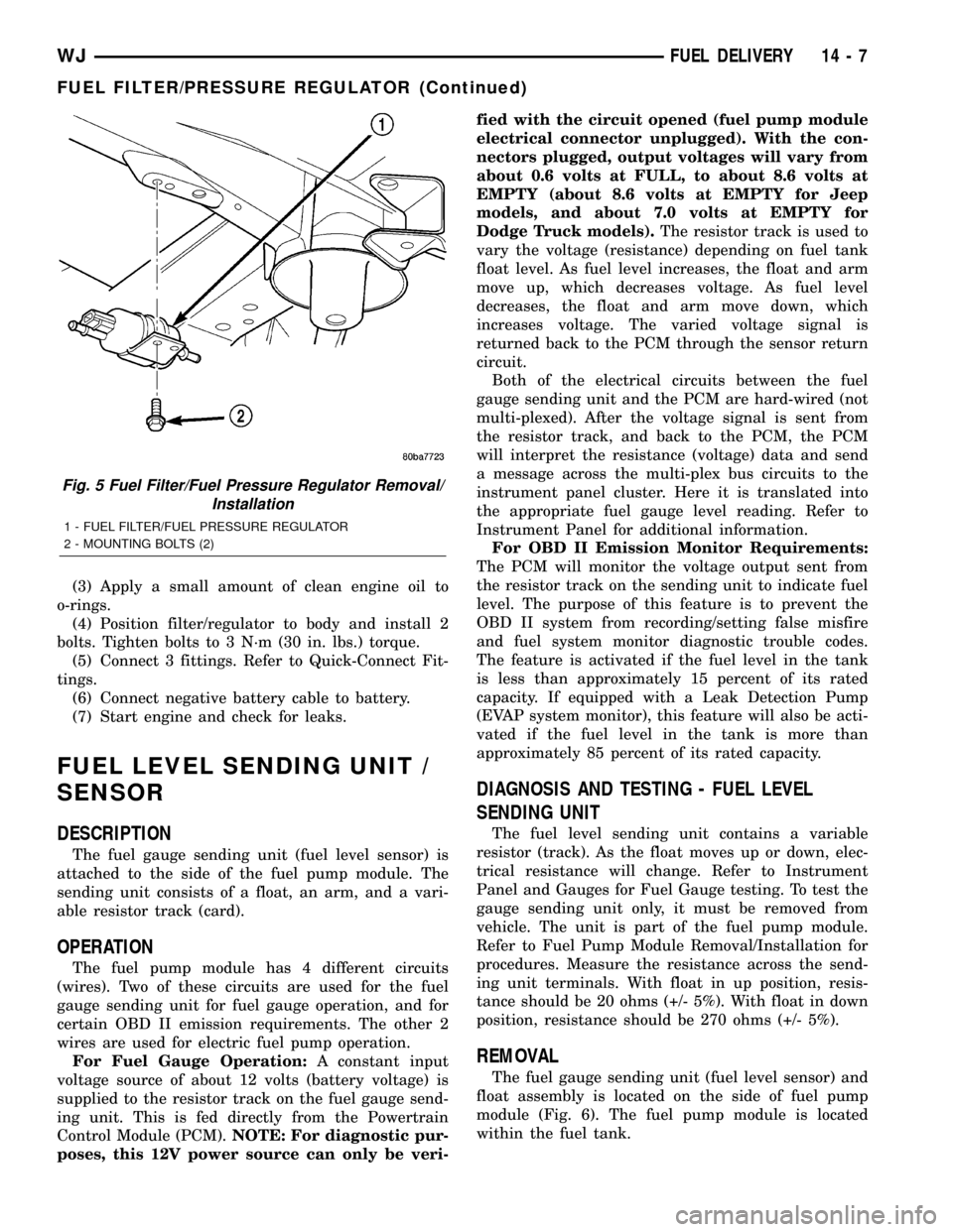
(3) Apply a small amount of clean engine oil to
o-rings.
(4) Position filter/regulator to body and install 2
bolts. Tighten bolts to 3 N´m (30 in. lbs.) torque.
(5) Connect 3 fittings. Refer to Quick-Connect Fit-
tings.
(6) Connect negative battery cable to battery.
(7) Start engine and check for leaks.
FUEL LEVEL SENDING UNIT /
SENSOR
DESCRIPTION
The fuel gauge sending unit (fuel level sensor) is
attached to the side of the fuel pump module. The
sending unit consists of a float, an arm, and a vari-
able resistor track (card).
OPERATION
The fuel pump module has 4 different circuits
(wires). Two of these circuits are used for the fuel
gauge sending unit for fuel gauge operation, and for
certain OBD II emission requirements. The other 2
wires are used for electric fuel pump operation.
For Fuel Gauge Operation:A constant input
voltage source of about 12 volts (battery voltage) is
supplied to the resistor track on the fuel gauge send-
ing unit. This is fed directly from the Powertrain
Control Module (PCM).NOTE: For diagnostic pur-
poses, this 12V power source can only be veri-fied with the circuit opened (fuel pump module
electrical connector unplugged). With the con-
nectors plugged, output voltages will vary from
about 0.6 volts at FULL, to about 8.6 volts at
EMPTY (about 8.6 volts at EMPTY for Jeep
models, and about 7.0 volts at EMPTY for
Dodge Truck models).The resistor track is used to
vary the voltage (resistance) depending on fuel tank
float level. As fuel level increases, the float and arm
move up, which decreases voltage. As fuel level
decreases, the float and arm move down, which
increases voltage. The varied voltage signal is
returned back to the PCM through the sensor return
circuit.
Both of the electrical circuits between the fuel
gauge sending unit and the PCM are hard-wired (not
multi-plexed). After the voltage signal is sent from
the resistor track, and back to the PCM, the PCM
will interpret the resistance (voltage) data and send
a message across the multi-plex bus circuits to the
instrument panel cluster. Here it is translated into
the appropriate fuel gauge level reading. Refer to
Instrument Panel for additional information.
For OBD II Emission Monitor Requirements:
The PCM will monitor the voltage output sent from
the resistor track on the sending unit to indicate fuel
level. The purpose of this feature is to prevent the
OBD II system from recording/setting false misfire
and fuel system monitor diagnostic trouble codes.
The feature is activated if the fuel level in the tank
is less than approximately 15 percent of its rated
capacity. If equipped with a Leak Detection Pump
(EVAP system monitor), this feature will also be acti-
vated if the fuel level in the tank is more than
approximately 85 percent of its rated capacity.
DIAGNOSIS AND TESTING - FUEL LEVEL
SENDING UNIT
The fuel level sending unit contains a variable
resistor (track). As the float moves up or down, elec-
trical resistance will change. Refer to Instrument
Panel and Gauges for Fuel Gauge testing. To test the
gauge sending unit only, it must be removed from
vehicle. The unit is part of the fuel pump module.
Refer to Fuel Pump Module Removal/Installation for
procedures. Measure the resistance across the send-
ing unit terminals. With float in up position, resis-
tance should be 20 ohms (+/- 5%). With float in down
position, resistance should be 270 ohms (+/- 5%).
REMOVAL
The fuel gauge sending unit (fuel level sensor) and
float assembly is located on the side of fuel pump
module (Fig. 6). The fuel pump module is located
within the fuel tank.
Fig. 5 Fuel Filter/Fuel Pressure Regulator Removal/
Installation
1 - FUEL FILTER/FUEL PRESSURE REGULATOR
2 - MOUNTING BOLTS (2)
WJFUEL DELIVERY 14 - 7
FUEL FILTER/PRESSURE REGULATOR (Continued)
Page 1438 of 2199

(14) Install air tube (or duct) at top of throttle
body.
(15) Install fuel tank cap.
(16) Connect negative battery cable to battery.
(17) Start engine and check for fuel leaks.
FUEL TANK
DESCRIPTION
The fuel tank is constructed of a plastic material.
Its main functions are for fuel storage and for place-
ment of the fuel pump module and certain ORVR
components.
OPERATION
All models pass a full 360 degree rollover test
without fuel leakage. To accomplish this, fuel and
vapor flow controls are required for all fuel tank con-
nections.
A fuel tank check valve(s) is mounted into the top
of the fuel tank (or pump module). Refer to Fuel
Tank Check Valve for additional information.
An evaporation control system is connected to the
check valve(s) to reduce emissions of fuel vapors into
the atmosphere. When fuel evaporates from the fuel
tank, vapors pass through vent hoses or tubes to a
charcoal canister where they are temporarily held.
When the engine is running, the vapors are drawn
into the intake manifold. Certain models are also
equipped with a self-diagnosing system using a Leak
Detection Pump (LDP). Refer to Emission Control
System for additional information.
Refer to ORVR for On-Board Refueling Vapor
Recovery system information.
REMOVAL
WARNING: THE FUEL SYSTEM IS UNDER CON-
STANT FUEL PRESSURE EVEN WITH ENGINE OFF.
PRESSURE MUST BE RELEASED BEFORE SERVIC-
ING FUEL TANK.
Two different procedures may be used to drain fuel
tank (through ORVR control valve opening at top of
fuel tank, or using DRB scan tool). The quickest is
draining through ORVR control valve opening at top
of fuel tank (Fig. 26).
As an alternative procedure, the electric fuel pump
may be activated allowing tank to be drained at fuel
rail connection. Refer to DRB scan tool for fuel pump
activation procedures. Before disconnecting fuel line
at fuel rail, release fuel pressure. Refer to the Fuel
System Pressure Release Procedure for procedures.
Attach end of Special Adapter Hose Tool number
6539 at fuel rail disconnection. Position opposite end
of 6539 to an approved gasoline draining station.Activate fuel pump with DRB and drain tank until
empty.
If electric fuel pump is not operating, tankMUST
be drained through ORVR control valve opening at
top of fuel tank (Fig. 26).
(1) Release fuel system pressure. Refer to Fuel
System Pressure Release Procedure.
(2) Disconnect negative battery cable at battery.
(3) Raise and support vehicle.
(4) Remove left rear wheel/tire.
CAUTION: HANDLE EVAP, LDP AND ORVR VAPOR /
VACUUM LINES VERY CAREFULLY. THESE LINES
AND HOSES MUST BE FIRMLY CONNECTED.
CHECK THE VAPOR/VACUUM LINES AT THE LDP,
LDP FILTER, EVAP CANISTER, EVAP CANISTER
PURGE SOLENOID AND ORVR COMPONENTS FOR
DAMAGE OR LEAKS. IF A LEAK IS PRESENT, A
DIAGNOSTIC TROUBLE CODE (DTC) MAY BE SET.
(5) Clean top of fuel tank at ORVR control valve
(Fig. 26) or (Fig. 27).
(6) Press release tab in direction of arrow in (Fig.
27) and remove ORVR control valve lock ring
(counter-clockwise). Lift up ORVR control slightly.
Using an approved gasoline draining station, drain
tank until empty through this opening.
(7) Remove stone shield behind left/rear wheel
(Fig. 28). Drill out plastic rivets for removal.
(8) Remove 3 LDP mounting bolts (Fig. 29).
(9) Remove support bracket brace bolt (Fig. 30).
(10) Loosen, but do not remove 2 support bracket
nuts at frame rail (Fig. 29).
(11) To separate and lower front section of two-
piece support bracket, remove 3 attaching bolts on
bottom of support bracket (Fig. 30). While lowering
support bracket, disconnect LDP wiring clip (Fig. 31).
(12) Remove hose clamp (Fig. 32) and remove fuel
fill hose from fuel fill tube.
(13) Cut and discard tie wrap from axle vent hose
(Fig. 32).
(14) Disconnect fuel vent hose from fuel vent tube
(Fig. 32).
(15) Disconnect ORVR hose elbow (Fig. 33) at top
of EVAP canister.
(16) Place hydraulic jack to bottom of fuel tank.
(17) Remove fuel tank-to-rear bumper fascia clips
(Fig. 34).
(18) Remove fuel tank heat shield mounting bolts
(Fig. 35).
CAUTION: To protect fuel tank from exhaust heat,
shield must re-installed after tank installation.
WARNING: PLACE SHOP TOWEL AROUND FUEL
LINES TO CATCH ANY EXCESS FUEL.
WJFUEL DELIVERY 14 - 19
FUEL RAIL (Continued)
Page 1439 of 2199
(19) Disconnect fuel return line at fuel filter/fuel
pressure regulator (Fig. 36). Refer to Quick-Connect
Fittings for procedures.
(20) Disconnect fuel pressure line at fuel filter/fuel
pressure regulator (Fig. 36). Refer to Quick-Connect
Fittings for procedures.
(21) Disconnect EVAP canister vent line near front
of tank (Fig. 36).
(22) Disconnect fuel pump module electrical con-
nector (pigtail harness) near front of tank (Fig. 36).
Harness connector is clipped to body.
(23) Remove left / front tank support bracket bolt
at frame (Fig. 37).
(24)WITHOUT TRAILER HITCH:Remove tank-
to-frame mounting bolts (Fig. 39). Remove rear tank
support bracket bolts at frame (Fig. 38). Carefully
lower tank until clear of vehicle. Place tank on floor.
(25)WITH TRAILER HITCH:Remove tank /
hitch mounting bolts (Fig. 40). Carefully lower tank
until clear of vehicle. Place tank on floor.
(26) If necessary, separate skid plate from fuel
tank by removing 2 fuel tank strap nuts (Fig. 39) and
remove 2 tank straps.
(27) If fuel pump module removal is necessary,
refer to Fuel Pump Module Removal/Installation.
(28) If hoses are to be removed at fuel tank end,
note painted alignment (indexing) markings on
hoses, and molded indexing tangs on tank before
removal. Remove hoses.
(29) If necessary, remove 3 fuel filler tube assem-
bly mounting bolts (Fig. 41) and remove fuel filler
tube.
INSTALLATION
CAUTION: HANDLE EVAP, LDP AND ORVR VAPOR /
VACUUM LINES VERY CAREFULLY. THESE LINES
AND HOSES MUST BE FIRMLY CONNECTED.
CHECK THE VAPOR/VACUUM LINES AT THE LDP,
LDP FILTER, EVAP CANISTER, EVAP CANISTER
PURGE SOLENOID AND ORVR COMPONENTS FOR
DAMAGE OR LEAKS. IF A LEAK IS PRESENT, A
DIAGNOSTIC TROUBLE CODE (DTC) MAY BE SET.
(1) If necessary, position fuel filler tube assembly
to body. Install 3 bolts and tighten to 2 N´m (15 in.
lbs.) torque.
(2) If necessary, connect quick-connect fittings to
fuel pump module.
(3) If fuel pump module is being installed, refer to
Fuel Pump Module Removal/Installation.
(4) Install fuel fill/vent hoses to tank fittings. To
prevent hoses from kinking, rotate each hose until
painted indexing mark on hose is aligned to molded
indexing tang on tank.
(5) Install hose clamps to hoses. Refer to Torque
Specifications.(6) If necessary, position fuel tank into skid plate.
Install 2 tank straps and 2 strap nuts (Fig. 39). Refer
to Torque Specifications.
(7) Position fuel tank / skid plate assembly to
hydraulic jack.
(8) Raise tank into position to frame.
(9)WITH TRAILER HITCH:Position trailer
hitch and tow hooks (Fig. 40) to bottom of fuel tank.
Install bolts and nuts loosely.
(10)WITHOUT TRAILER HITCH:Install 2 rear
tank support brackets and bolts (Fig. 38). Install
tank-to-frame bolts. Do not tighten bolts / nuts at
this time.
(11) Install 1 left / front tank support bracket and
bolts / nuts (Fig. 37). Do not tighten bolts / nuts at
this time.
(12) Be sure fuel tank is properly aligned to frame
and body. Tighten all tank, tow hook and trailer
hitch bolts / nuts except for 3 support brackets.
Tighten all 3 (2 rear and 1 left / front) support
bracket bolts / nuts last. Refer to Torque Specifica-
tions.
(13)
(14) Connect fuel pump module pigtail harness
electrical connector near front of tank.
(15) Connect both fuel lines to fuel filter/fuel pres-
sure regulator. Refer to Quick-Connect Fittings for
procedures.
(16) Connect EVAP hose near front of tank.
(17) Position rear axle vent hose and install new
tie strap (Fig. 32).
(18) Install heat shield nuts / bolts (Fig. 35). Refer
to Torque Specifications.
(19) Connect ORVR hose elbow (Fig. 33) to top of
EVAP canister.
(20) Connect fuel vent hose to fuel vent tube (Fig.
32).
(21) Install fuel fill hose and clamp to fuel fill tube
(Fig. 32).
(22) Install 3 LDP mounting bolts (Fig. 29).
(23) While raising support bracket, connect LDP
wiring clip (Fig. 31). Install front section of two-piece
support bracket to rear section with 3 attaching bolts
located on bottom of support bracket (Fig. 30).
(24) Install support bracket brace bolt (Fig. 30).
(25) Tighten 2 support bracket nuts at frame rail
(Fig. 29).
(26) Install fuel tank-to-rear bumper fascia clips
(Fig. 34).
(27) Using new plastic rivets, install stone shield
behind left/rear wheel (Fig. 28).
(28) Install left rear wheel/tire.
(29) Lower vehicle and connect negative battery
cable to battery.
(30) Fill tank with fuel and check for leaks.
14 - 20 FUEL DELIVERYWJ
FUEL TANK (Continued)