Flush JEEP GRAND CHEROKEE 2003 WJ / 2.G Repair Manual
[x] Cancel search | Manufacturer: JEEP, Model Year: 2003, Model line: GRAND CHEROKEE, Model: JEEP GRAND CHEROKEE 2003 WJ / 2.GPages: 2199, PDF Size: 76.01 MB
Page 1968 of 2199
INSTALLATION
WARNING: REVIEW ALL WARNINGS AND CAU-
TIONS IN THIS GROUP BEFORE PRECEDING WITH
INSTALLATION.
CAUTION: Open a window before installing wind-
shield. This will avoid pressurizing the passenger
compartment. If a door or liftgate is slammed before
urethane is cured, water leaks can result.
The windshield fence should be cleaned of old ure-
thane bonding material. Support spacers should be
cleaned and properly installed on weld studs or
repair screws at bottom of windshield opening.
(1)
Place replacement windshield into windshield
opening. Position glass in the center of the opening
against the support spacers. Mark the glass at the sup-
port spacers with a grease pencil or masking tape and
ink pen to use as a reference for installation. Remove
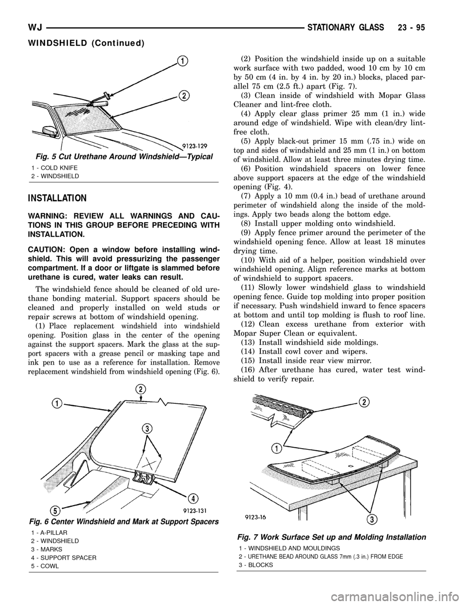
replacement windshield from windshield opening (Fig. 6).
(2) Position the windshield inside up on a suitable
work surface with two padded, wood 10 cm by 10 cm
by 50 cm (4 in. by 4 in. by 20 in.) blocks, placed par-
allel 75 cm (2.5 ft.) apart (Fig. 7).
(3) Clean inside of windshield with Mopar Glass
Cleaner and lint-free cloth.
(4) Apply clear glass primer 25 mm (1 in.) wide
around edge of windshield. Wipe with clean/dry lint-
free cloth.
(5)
Apply black-out primer 15 mm (.75 in.) wide on
top and sides of windshield and 25 mm (1 in.) on bottom
of windshield. Allow at least three minutes drying time.
(6) Position windshield spacers on lower fence
above support spacers at the edge of the windshield
opening (Fig. 4).
(7)
Apply a 10 mm (0.4 in.) bead of urethane around
perimeter of windshield along the inside of the mold-
ings. Apply two beads along the bottom edge.
(8) Install upper molding onto windshield.
(9) Apply fence primer around the perimeter of the
windshield opening fence. Allow at least 18 minutes
drying time.
(10) With aid of a helper, position windshield over
windshield opening. Align reference marks at bottom
of windshield to support spacers.
(11) Slowly lower windshield glass to windshield
opening fence. Guide top molding into proper position
if necessary. Push windshield inward to fence spacers
at bottom and until top molding is flush to roof line.
(12) Clean excess urethane from exterior with
Mopar Super Clean or equivalent.
(13) Install windshield side moldings.
(14) Install cowl cover and wipers.
(15) Install inside rear view mirror.
(16) After urethane has cured, water test wind-
shield to verify repair.
Fig. 6 Center Windshield and Mark at Support Spacers
1 - A-PILLAR
2 - WINDSHIELD
3 - MARKS
4 - SUPPORT SPACER
5 - COWLFig. 7 Work Surface Set up and Molding Installation
1 - WINDSHIELD AND MOULDINGS
2-
URETHANE BEAD AROUND GLASS 7mm (.3 in.) FROM EDGE
3 - BLOCKS
Fig. 5 Cut Urethane Around WindshieldÐTypical
1 - COLD KNIFE
2 - WINDSHIELD
WJSTATIONARY GLASS 23 - 95
WINDSHIELD (Continued)
Page 1970 of 2199
releasing the control switch before the sunroof was
fully closed. The sunroof module has a water-man-
agement system. During washing high-pressure
water may be forced between the glass panel seal
and the roof opening. Normally this water will drain.
However, when some type of drying blower system is
used, like those found in automatic car washes, thewater may not have a chance to drain before the
blower forces air between the seal and the roof open-
ing. This causes the water to blow over the edge of
the module and onto the headlining.
Refer to (Fig. 1) Sunroof Assembly for exploded
view of the sunroof.
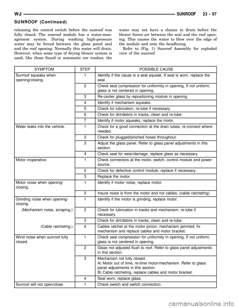
SYMPTOM STEP POSSIBLE CAUSE
Sunroof squeaks when
opening/closing.1 Identify if the cause is a seal squeak. If seal is worn, replace the
seal.
2 Check seal compression for uniformity in opening, If not uniform,
glass is not centered in opening.
3 Re-center glass by repositioning module in opening.
4 Identify if mechanism squeaks.
5 Check for lubrication, re-lube if necessary.
6 Check for dirt/debris in tracks, clean and re-lube.
7 Identify if motor squeaks, replace the motor.
Water leaks into the vehicle. 1 Check for a good connection at the drain tubes, re-connect where
needed.
2 Check for plugged/pinched hoses throughout.
3 Adjust the glass panel. Refer to glass panel adjustments in this
section.
4 Check seal for wear/damage, replace glass as necessary.
Motor inoperative. 1 Check connectors at the motor, switch, control module and power
source.
2 Check for defective control module, replace if necessary.
3 Replace the motor.
Motor noise when opening/
closing.1 Identify if motor noise, replace motor.
2 Insure noise is from the motor and not cables, (cable ratcheting).
Grinding noise when opening/
closing.1 Identify if the motor is grinding, replace motor.
(Mechanism noise, scraping.) 2 Check for lubrication in tracks and mechanism, re-lube if
necessary.
3 Check for dirt/debris in tracks, clean and re-lube.
(Cable ratcheting.) 4 Cables ratchet at the motor pinion; mechanism jammed, fix
mechanism and replace cables and motor bracket.
Wind noise when sunroof fully
closed.1 Check seal compression for uniformity in opening, If not uniform,
glass is not centered in opening.
2 Glass not adjusted flush to roof. Refer to glass panel adjustments
in this section.
3 Mechanism not fully closed.
A) Motor out of time, re-time motor/mechanism. Refer to glass
panel adjustments in this section.
B) Cable ratcheting, replace cables and motor bracket.
4 Seal worn, replace glass.
Sunroof will not open/close. 1 Check switch and switch connection.
WJSUNROOF 23 - 97
SUNROOF (Continued)
Page 1976 of 2199
INSTALLATION
NOTE: Sunroof glass must be set in place and
attached as close as possible to flush with the roof
surface. For wind noise reasons, care must be
taken to ensure that the glass is not remounted
either a) Overflush to the roof surface at the front
edge of the glass, or b) Underflush to the roof sur-
face at the rear edge of the glass.
(1) Position glass panel in to opening.
(2) Start the four attaching screws.
(3) Tighten screws.
(4) Verify sunroof operation and alignment. Check
fit and adjust as necessary. (Refer to 23 - BODY/
SUNROOF/GLASS PANEL - ADJUSTMENTS - FIT)
ADJUSTMENTS
ADJUSTMENTS - FIT
(1) Move the sunshade rearward to the open posi-
tion.
(2) Move the sunroof glass panel to the fully closed
position.
(3) Loosen the forward screws on each side enough
to make the front adjustment.
(4) Adjust the front of the sunroof glass panel 1
mm (1/32 inch) below the top surface of the roof
panel.
(5) Tighten the front two screws.
(6) Loosen the rear screws on each side enough to
make the rear adjustment.
(7) Adjust the rear of the sunroof glass panel 1
mm (1/32 inch) above the top surface of the roof
panel.
(8) Tighten the rear two screws.
(9) Check for proper fit. If not OK, repeat glass
panel adjustment.
ADJUSTMENT - TIMING
NOTE: A gage comes with the new motor.
(1) If the glass panel was not in the fully closed
position, when the motor was removed, the sunroof
glass panel needs to be timed, before the new motor
is installed.
(2) Remove sunroof glass panel.
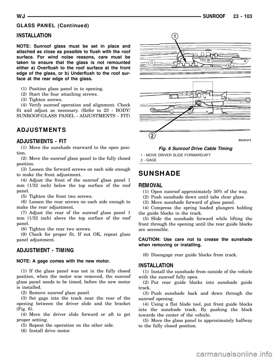
(3) Set gage into the track near the rear of the
opening between the driver slide and the bracket
(Fig. 6).
(4) Move the driver slide forward or aft to get
proper setting.
(5) Repeat the operation on the other side.
(6) Install drive motor.
SUNSHADE
REMOVAL
(1) Open sunroof approximately 50% of the way.
(2) Push sunshade down until tabs clear glass.
(3) Move sunshade forward of glass panel.
(4) Compress the spring loaded plungers holding
the guide blocks in the track.
(5) Slide the sunshade forward while lifting the
front through the opening until the rear guide blocks
are accessible.
CAUTION: Use care not to crease the sunshade
when removing or installing.
(6) Disengage rear guide blocks from track.
INSTALLATION
(1) Install the sunshade from outside of the vehicle
with the sunroof fully open.
(2) Put rear guide blocks into sunshade guide
track.
(3) Push sunshade back and down through the
sunroof opening.
(4) Using a flat blade tool, put front guide blocks
into the sunshade track. By pushing the block
towards the center of the vehicle.
(5) Move the glass panel to approximately halfway
to the fully closed position.
Fig. 6 Sunroof Drive Cable Timing
1 - MOVE DRIVER SLIDE FORWARD/AFT
2 - GAGE
WJSUNROOF 23 - 103
GLASS PANEL (Continued)
Page 1984 of 2199
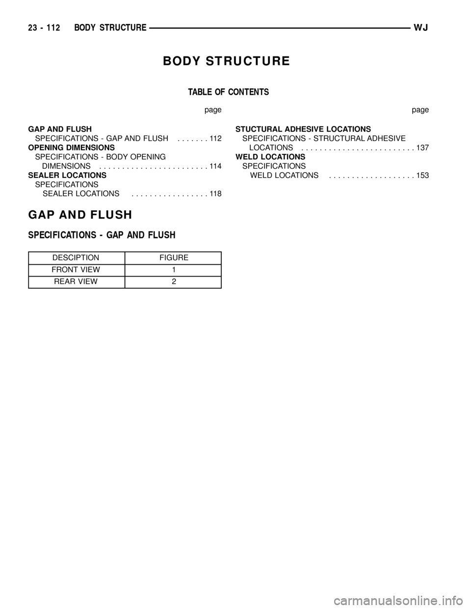
BODY STRUCTURE
TABLE OF CONTENTS
page page
GAP AND FLUSH
SPECIFICATIONS - GAP AND FLUSH.......112
OPENING DIMENSIONS
SPECIFICATIONS - BODY OPENING
DIMENSIONS........................114
SEALER LOCATIONS
SPECIFICATIONS
SEALER LOCATIONS.................118STUCTURAL ADHESIVE LOCATIONS
SPECIFICATIONS - STRUCTURAL ADHESIVE
LOCATIONS.........................137
WELD LOCATIONS
SPECIFICATIONS
WELD LOCATIONS...................153
GAP AND FLUSH
SPECIFICATIONS - GAP AND FLUSH
DESCIPTION FIGURE
FRONT VIEW 1
REAR VIEW 2
23 - 112 BODY STRUCTUREWJ
Page 1985 of 2199
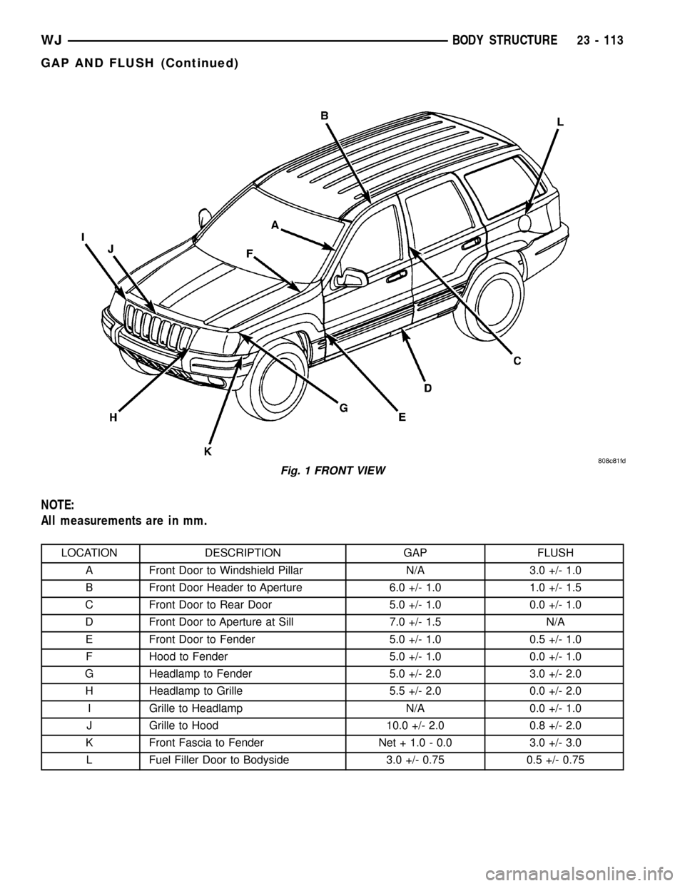
NOTE:
All measurements are in mm.
LOCATION DESCRIPTION GAP FLUSH
A Front Door to Windshield Pillar N/A 3.0 +/- 1.0
B Front Door Header to Aperture 6.0 +/- 1.0 1.0 +/- 1.5
C Front Door to Rear Door 5.0 +/- 1.0 0.0 +/- 1.0
D Front Door to Aperture at Sill 7.0 +/- 1.5 N/A
E Front Door to Fender 5.0 +/- 1.0 0.5 +/- 1.0
F Hood to Fender 5.0 +/- 1.0 0.0 +/- 1.0
G Headlamp to Fender 5.0 +/- 2.0 3.0 +/- 2.0
H Headlamp to Grille 5.5 +/- 2.0 0.0 +/- 2.0
I Grille to Headlamp N/A 0.0 +/- 1.0
J Grille to Hood 10.0 +/- 2.0 0.8 +/- 2.0
K Front Fascia to Fender Net + 1.0 - 0.0 3.0 +/- 3.0
L Fuel Filler Door to Bodyside 3.0 +/- 0.75 0.5 +/- 0.75
Fig. 1 FRONT VIEW
WJBODY STRUCTURE 23 - 113
GAP AND FLUSH (Continued)
Page 1986 of 2199
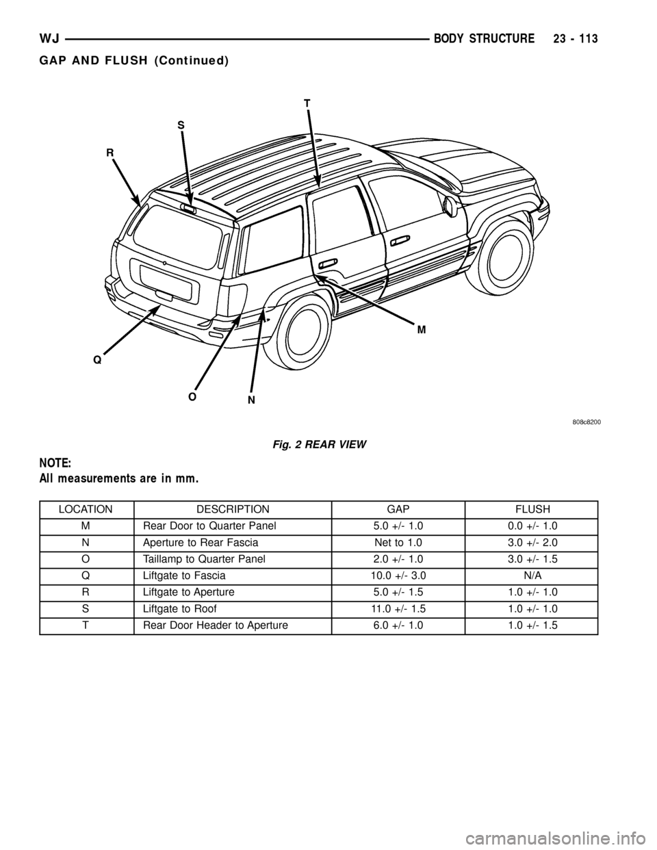
NOTE:
All measurements are in mm.
LOCATION DESCRIPTION GAP FLUSH
M Rear Door to Quarter Panel 5.0 +/- 1.0 0.0 +/- 1.0
N Aperture to Rear Fascia Net to 1.0 3.0 +/- 2.0
O Taillamp to Quarter Panel 2.0 +/- 1.0 3.0 +/- 1.5
Q Liftgate to Fascia 10.0 +/- 3.0 N/A
R Liftgate to Aperture 5.0 +/- 1.5 1.0 +/- 1.0
S Liftgate to Roof 11.0 +/- 1.5 1.0 +/- 1.0
T Rear Door Header to Aperture 6.0 +/- 1.0 1.0 +/- 1.5
Fig. 2 REAR VIEW
WJBODY STRUCTURE 23 - 113
GAP AND FLUSH (Continued)