Boot JEEP GRAND CHEROKEE 2003 WJ / 2.G Workshop Manual
[x] Cancel search | Manufacturer: JEEP, Model Year: 2003, Model line: GRAND CHEROKEE, Model: JEEP GRAND CHEROKEE 2003 WJ / 2.GPages: 2199, PDF Size: 76.01 MB
Page 51 of 2199
PROPELLER SHAFT - FRONT
REMOVAL
NOTE: Different length propeller shafts are used for
different drivetrain applications. Ensure that the
correct propeller shaft is used.
(1) Place vehicle on floor or drive-on hoist with full
weight of vehicle on suspension.
(2) Shift the transmission and transfer case, if nec-
essary, into the Neutral position.
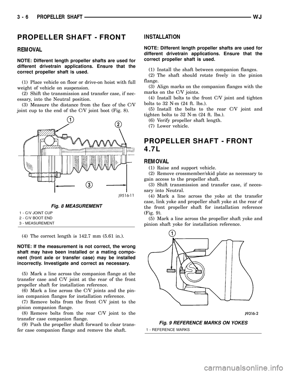
(3) Measure the distance from the face of the C/V
joint cup to the end of the C/V joint boot (Fig. 8).
(4) The correct length is 142.7 mm (5.61 in.).
NOTE: If the measurement is not correct, the wrong
shaft may have been installed or a mating compo-
nent (front axle or transfer case) may be installed
incorrectly. Investigate and correct as necessary.
(5) Mark a line across the companion flange at the
transfer case and C/V joint at the rear of the front
propeller shaft for installation reference.
(6) Mark a line across the C/V joints and the pin-
ion companion flanges for installation reference.
(7) Remove bolts from the front C/V joint to the
pinion companion flange.
(8) Remove bolts from the rear C/V joint to the
transfer case companion flange.
(9) Push the propeller shaft forward to clear trans-
fer case companion flange and remove the shaft.
INSTALLATION
NOTE: Different length propeller shafts are used for
different drivetrain applications. Ensure that the
correct propeller shaft is used.
(1) Install the shaft between companion flanges.
(2) The shaft should rotate freely in the pinion
flange.
(3) Align marks on the companion flanges with the
marks on the C/V joints.
(4) Install bolts to the front C/V joint and tighten
bolts to 32 N´m (24 ft. lbs.).
(5) Install the bolts to the rear C/V joint and
tighten bolts to 32 N´m (24 ft. lbs.).
(6) Verify propeller shaft length.
(7) Lower vehicle.
PROPELLER SHAFT - FRONT
4.7L
REMOVAL
(1) Raise and support vehicle.
(2) Remove crossmember/skid plate as necessary to
gain access to the propeller shaft.
(3) Shift transmission and transfer case, if neces-
sary into Neutral.
(4) Mark a line across the yoke at the transfer
case, link yoke and propeller shaft yoke at the rear of
the front propeller shaft for installation reference
(Fig. 9).
(5) Mark a line across the propeller shaft yoke and
pinion shaft yoke for installation reference.
Fig. 8 MEASUREMENT
1 - C/V JOINT CUP
2 - C/V BOOT END
3 - MEASUREMENT
Fig. 9 REFERENCE MARKS ON YOKES
1 - REFERENCE MARKS
3 - 6 PROPELLER SHAFTWJ
Page 52 of 2199
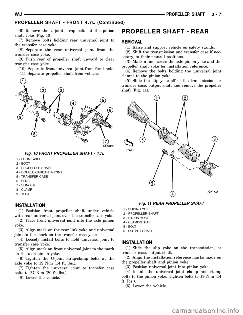
(6) Remove the U-joint strap bolts at the pinion
shaft yoke (Fig. 10).
(7) Remove bolts holding rear universal joint to
the transfer case yoke.
(8) Separate the rear universal joint from the
transfer case yoke.
(9) Push rear of propeller shaft upward to clear
transfer case yoke.
(10) Separate front universal joint from front axle.
(11) Separate propeller shaft from vehicle.
INSTALLATION
(1) Position front propeller shaft under vehicle
with rear universal joint over the transfer case yoke.
(2) Place front universal joint into the axle pinion
yoke.
(3) Align mark on the rear link yoke and universal
joint to the mark on the transfer case yoke.
(4) Loosely install bolts to hold universal joint to
transfer case yoke.
(5) Align mark on front universal joint to the mark
on the axle pinion yoke.
(6) Tighten the U-joint strap/clamp bolts at the
axle yoke to 19 N´m (14 ft. lbs.).
(7) Tighten the universal joint to transfer case
bolts to 27 N´m (20 ft. lbs.).
(8) Lower the vehicle.
PROPELLER SHAFT - REAR
REMOVAL
(1) Raise and support vehicle on safety stands.
(2) Shift the transmission and transfer case if nec-
essary, to their neutral positions.
(3) Mark a line across the axle pinion yoke and the
propeller shaft yoke for installation reference.
(4) Remove the bolts holding the universal joint
clamps to the pinion yoke.
(5) Slide the slip yoke off of the transmission, or
transfer case, output shaft and remove the propeller
shaft (Fig. 11).
INSTALLATION
(1) Slide the slip yoke on the transmission, or
transfer case, output shaft.
(2) Align the installation reference marks made on
the propeller shaft and pinion yoke.
(3) Position universal joint into pinion yoke.
(4) Install the universal joint clamp and clamp
bolts to the pinion yoke. Tighten bolts to 19 N´m (14
ft. lbs.).
(5) Lower the vehicle.
Fig. 10 FRONT PROPELLER SHAFT - 4.7L
1 - FRONT AXLE
2 - BOOT
3 - PROPELLER SHAFT
4 - DOUBLE CARDAN U-JOINT
5 - TRANSFER CASE
6 - BOOT
7 - SLINGER
8 - CLAMP
9 - YOKE
Fig. 11 REAR PROPELLER SHAFT
1 - SLIDING YOKE
2 - PROPELLER SHAFT
3 - PINION YOKE
4 - CLAMP/STRAP
5 - BOLT
6 - OUTPUT SHAFT
WJPROPELLER SHAFT 3 - 7
PROPELLER SHAFT - FRONT 4.7L (Continued)
Page 80 of 2199
AXLE SHAFT SEALS
REMOVAL
(1) Raise and support vehicle.
(2) Remove axle shafts.
(3) Remove differential assembly.
(4) Remove inner axle shaft seals with a pry bay.
INSTALLATION
(1) Remove any sealer remaining from original
seals.
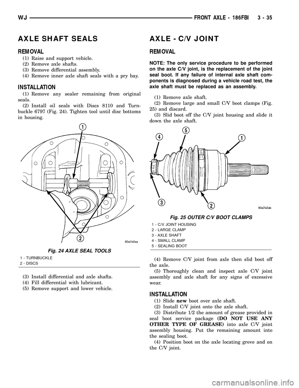
(2) Install oil seals with Discs 8110 and Turn-
buckle 6797 (Fig. 24). Tighten tool until disc bottoms
in housing.
(3) Install differential and axle shafts.
(4) Fill differential with lubricant.
(5) Remove support and lower vehicle.
AXLE - C/V JOINT
REMOVAL
NOTE: The only service procedure to be performed
on the axle C/V joint, is the replacement of the joint
seal boot. If any failure of internal axle shaft com-
ponents is diagnosed during a vehicle road test, the
axle shaft must be replaced as an assembly.
(1) Remove axle shaft.
(2) Remove large and small C/V boot clamps (Fig.
25) and discard.
(3) Slid boot off the C/V joint housing and slide it
down the axle shaft.
(4) Remove C/V joint from axle then slid boot off
the axle.
(5) Thoroughly clean and inspect axle C/V joint
assembly and axle shaft for any signs of excessive
wear.
INSTALLATION
(1) Slidenewboot over axle shaft.
(2) Install C/V joint onto the axle shaft.
(3) Distribute 1/2 the amount of grease provided in
seal boot service package(DO NOT USE ANY
OTHER TYPE OF GREASE)into axle C/V joint
assembly housing. Put the remaining amount into
the sealing boot.
(4) Position boot on the axle locating grove and on
the C/V joint.
Fig. 24 AXLE SEAL TOOLS
1 - TURNBUCKLE
2 - DISCS
Fig. 25 OUTER C/V BOOT CLAMPS
1 - C/V JOINT HOUSING
2 - LARGE CLAMP
3 - AXLE SHAFT
4 - SMALL CLAMP
5 - SEALING BOOT
WJFRONT AXLE - 186FBI 3 - 35
Page 81 of 2199
CAUTION: Boot must not be dimpled, stretched or
out of shape in any way. If not shaped correctly,
equalize pressure in boot and shape it by hand.
(5) Install the two boot clamps.
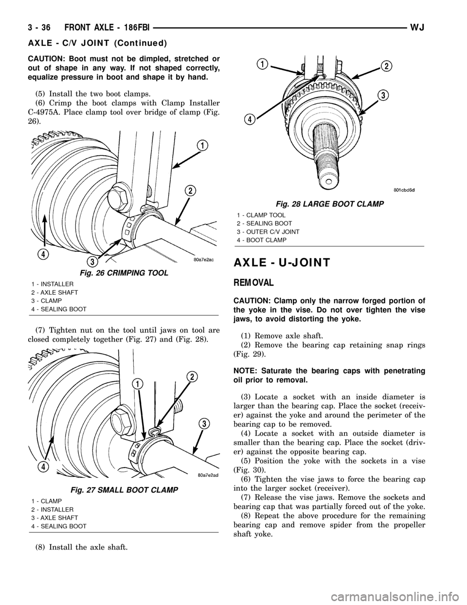
(6) Crimp the boot clamps with Clamp Installer
C-4975A. Place clamp tool over bridge of clamp (Fig.
26).
(7) Tighten nut on the tool until jaws on tool are
closed completely together (Fig. 27) and (Fig. 28).
(8) Install the axle shaft.
AXLE - U-JOINT
REMOVAL
CAUTION: Clamp only the narrow forged portion of
the yoke in the vise. Do not over tighten the vise
jaws, to avoid distorting the yoke.
(1) Remove axle shaft.
(2) Remove the bearing cap retaining snap rings
(Fig. 29).
NOTE: Saturate the bearing caps with penetrating
oil prior to removal.
(3) Locate a socket with an inside diameter is
larger than the bearing cap. Place the socket (receiv-
er) against the yoke and around the perimeter of the
bearing cap to be removed.
(4) Locate a socket with an outside diameter is
smaller than the bearing cap. Place the socket (driv-
er) against the opposite bearing cap.
(5) Position the yoke with the sockets in a vise
(Fig. 30).
(6) Tighten the vise jaws to force the bearing cap
into the larger socket (receiver).
(7) Release the vise jaws. Remove the sockets and
bearing cap that was partially forced out of the yoke.
(8) Repeat the above procedure for the remaining
bearing cap and remove spider from the propeller
shaft yoke.
Fig. 26 CRIMPING TOOL
1 - INSTALLER
2 - AXLE SHAFT
3 - CLAMP
4 - SEALING BOOT
Fig. 27 SMALL BOOT CLAMP
1 - CLAMP
2 - INSTALLER
3 - AXLE SHAFT
4 - SEALING BOOT
Fig. 28 LARGE BOOT CLAMP
1 - CLAMP TOOL
2 - SEALING BOOT
3 - OUTER C/V JOINT
4 - BOOT CLAMP
3 - 36 FRONT AXLE - 186FBIWJ
AXLE - C/V JOINT (Continued)
Page 182 of 2199
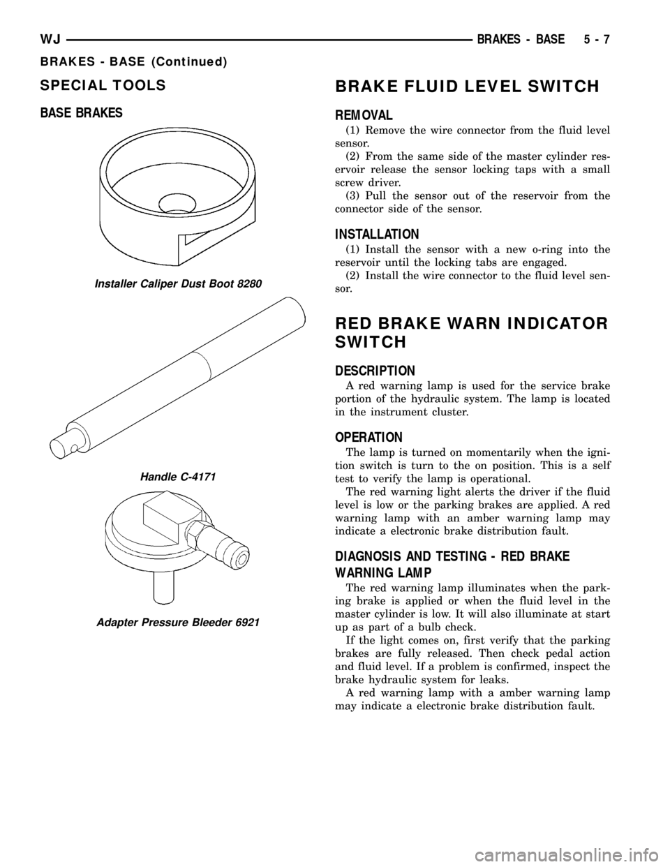
SPECIAL TOOLS
BASE BRAKESBRAKE FLUID LEVEL SWITCH
REMOVAL
(1) Remove the wire connector from the fluid level
sensor.
(2) From the same side of the master cylinder res-
ervoir release the sensor locking taps with a small
screw driver.
(3) Pull the sensor out of the reservoir from the
connector side of the sensor.
INSTALLATION
(1) Install the sensor with a new o-ring into the
reservoir until the locking tabs are engaged.
(2) Install the wire connector to the fluid level sen-
sor.
RED BRAKE WARN INDICATOR
SWITCH
DESCRIPTION
A red warning lamp is used for the service brake
portion of the hydraulic system. The lamp is located
in the instrument cluster.
OPERATION
The lamp is turned on momentarily when the igni-
tion switch is turn to the on position. This is a self
test to verify the lamp is operational.
The red warning light alerts the driver if the fluid
level is low or the parking brakes are applied. A red
warning lamp with an amber warning lamp may
indicate a electronic brake distribution fault.
DIAGNOSIS AND TESTING - RED BRAKE
WARNING LAMP
The red warning lamp illuminates when the park-
ing brake is applied or when the fluid level in the
master cylinder is low. It will also illuminate at start
up as part of a bulb check.
If the light comes on, first verify that the parking
brakes are fully released. Then check pedal action
and fluid level. If a problem is confirmed, inspect the
brake hydraulic system for leaks.
A red warning lamp with a amber warning lamp
may indicate a electronic brake distribution fault.
Installer Caliper Dust Boot 8280
Handle C-4171
Adapter Pressure Bleeder 6921
WJBRAKES - BASE 5 - 7
BRAKES - BASE (Continued)
Page 186 of 2199
shoe lining against the inner surface of the disc
brake rotor. At the same time, fluid pressure within
the piston bores forces the caliper to slide inward on
the slide pins. This action brings the outboard brake
shoe lining into contact with the outer surface of the
disc brake rotor.
Fluid pressure acting simultaneously on the pis-
tons and caliper to produces a strong clamping
action. When sufficient force is applied, friction will
stop the rotors from turning and bring the vehicle to
a stop.
Application and release of the brake pedal gener-
ates only a very slight movement of the caliper and
pistons. Upon release of the pedal, the caliper and
pistons return to a rest position. The brake shoes do
not retract an appreciable distance from the rotor. In
fact, clearance is usually at, or close to zero. The rea-
sons for this are to keep road debris from getting
between the rotor and lining and in wiping the rotor
surface clear each revolution.
The caliper piston seals control the amount of pis-
ton extension needed to compensate for normal lining
wear.
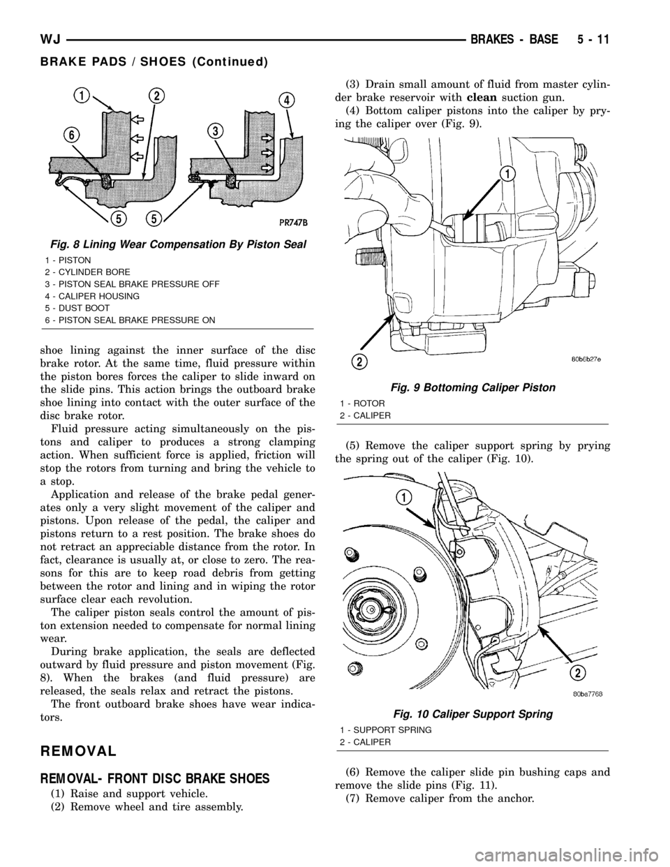
During brake application, the seals are deflected
outward by fluid pressure and piston movement (Fig.
8). When the brakes (and fluid pressure) are
released, the seals relax and retract the pistons.
The front outboard brake shoes have wear indica-
tors.
REMOVAL
REMOVAL- FRONT DISC BRAKE SHOES
(1) Raise and support vehicle.
(2) Remove wheel and tire assembly.(3) Drain small amount of fluid from master cylin-
der brake reservoir withcleansuction gun.
(4) Bottom caliper pistons into the caliper by pry-
ing the caliper over (Fig. 9).
(5) Remove the caliper support spring by prying
the spring out of the caliper (Fig. 10).
(6) Remove the caliper slide pin bushing caps and
remove the slide pins (Fig. 11).
(7) Remove caliper from the anchor.
Fig. 8 Lining Wear Compensation By Piston Seal
1 - PISTON
2 - CYLINDER BORE
3 - PISTON SEAL BRAKE PRESSURE OFF
4 - CALIPER HOUSING
5 - DUST BOOT
6 - PISTON SEAL BRAKE PRESSURE ON
Fig. 9 Bottoming Caliper Piston
1 - ROTOR
2 - CALIPER
Fig. 10 Caliper Support Spring
1 - SUPPORT SPRING
2 - CALIPER
WJBRAKES - BASE 5 - 11
BRAKE PADS / SHOES (Continued)
Page 192 of 2199
DISASSEMBLY
DISASSEMBLY - FRONT DISC BRAKE CALIPER
(1) Drain the brake fluid from caliper.
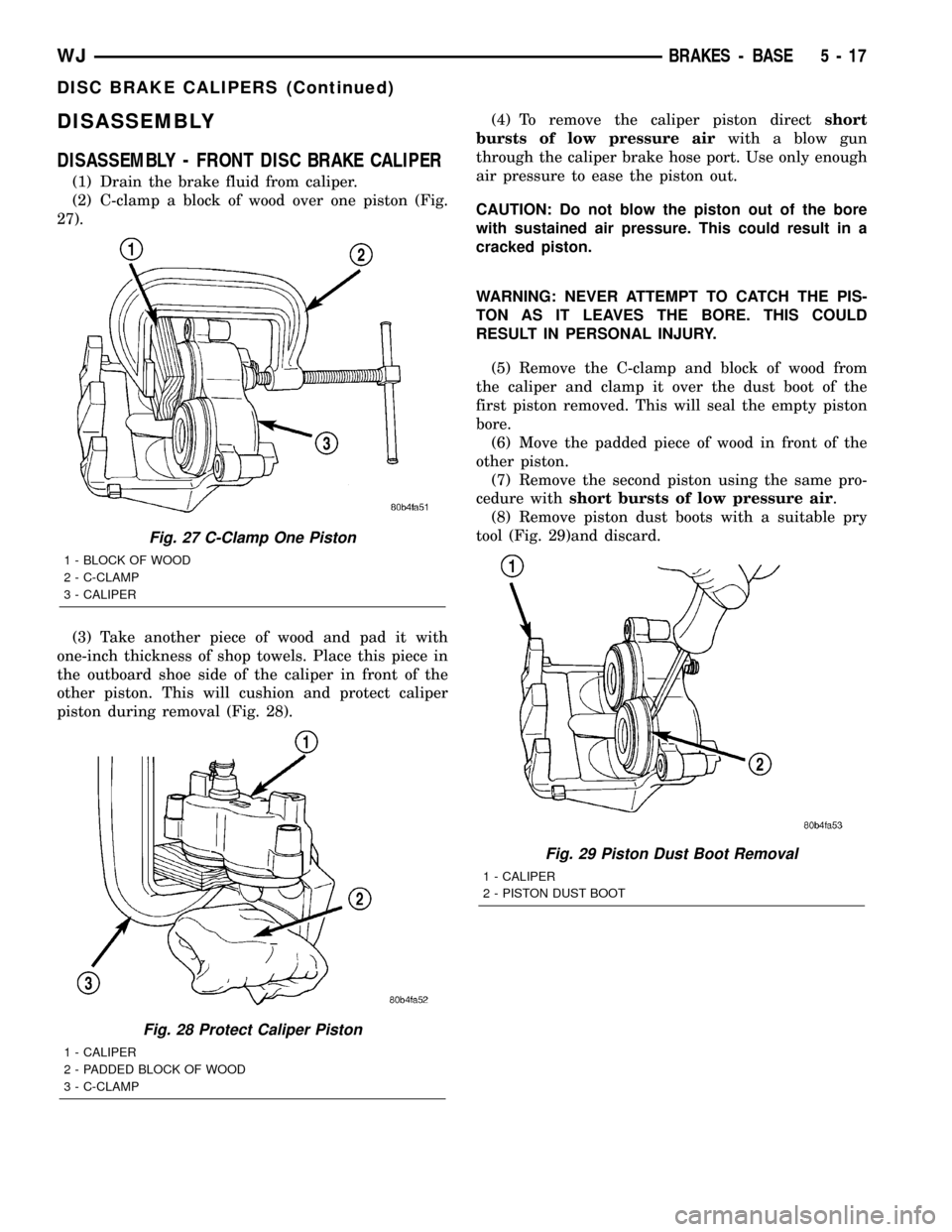
(2) C-clamp a block of wood over one piston (Fig.
27).
(3) Take another piece of wood and pad it with
one-inch thickness of shop towels. Place this piece in
the outboard shoe side of the caliper in front of the
other piston. This will cushion and protect caliper
piston during removal (Fig. 28).(4) To remove the caliper piston directshort
bursts of low pressure airwith a blow gun
through the caliper brake hose port. Use only enough
air pressure to ease the piston out.
CAUTION: Do not blow the piston out of the bore
with sustained air pressure. This could result in a
cracked piston.
WARNING: NEVER ATTEMPT TO CATCH THE PIS-
TON AS IT LEAVES THE BORE. THIS COULD
RESULT IN PERSONAL INJURY.
(5) Remove the C-clamp and block of wood from
the caliper and clamp it over the dust boot of the
first piston removed. This will seal the empty piston
bore.
(6) Move the padded piece of wood in front of the
other piston.
(7) Remove the second piston using the same pro-
cedure withshort bursts of low pressure air.
(8) Remove piston dust boots with a suitable pry
tool (Fig. 29)and discard.
Fig. 27 C-Clamp One Piston
1 - BLOCK OF WOOD
2 - C-CLAMP
3 - CALIPER
Fig. 28 Protect Caliper Piston
1 - CALIPER
2 - PADDED BLOCK OF WOOD
3 - C-CLAMP
Fig. 29 Piston Dust Boot Removal
1 - CALIPER
2 - PISTON DUST BOOT
WJBRAKES - BASE 5 - 17
DISC BRAKE CALIPERS (Continued)
Page 194 of 2199
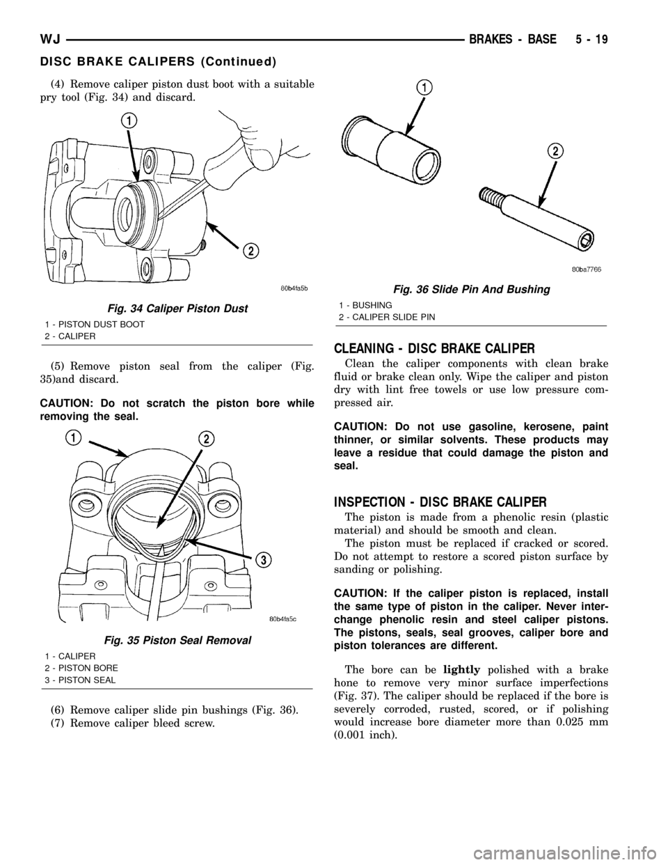
(4) Remove caliper piston dust boot with a suitable
pry tool (Fig. 34) and discard.
(5) Remove piston seal from the caliper (Fig.
35)and discard.
CAUTION: Do not scratch the piston bore while
removing the seal.
(6) Remove caliper slide pin bushings (Fig. 36).
(7) Remove caliper bleed screw.
CLEANING - DISC BRAKE CALIPER
Clean the caliper components with clean brake
fluid or brake clean only. Wipe the caliper and piston
dry with lint free towels or use low pressure com-
pressed air.
CAUTION: Do not use gasoline, kerosene, paint
thinner, or similar solvents. These products may
leave a residue that could damage the piston and
seal.
INSPECTION - DISC BRAKE CALIPER
The piston is made from a phenolic resin (plastic
material) and should be smooth and clean.
The piston must be replaced if cracked or scored.
Do not attempt to restore a scored piston surface by
sanding or polishing.
CAUTION: If the caliper piston is replaced, install
the same type of piston in the caliper. Never inter-
change phenolic resin and steel caliper pistons.
The pistons, seals, seal grooves, caliper bore and
piston tolerances are different.
The bore can belightlypolished with a brake
hone to remove very minor surface imperfections
(Fig. 37). The caliper should be replaced if the bore is
severely corroded, rusted, scored, or if polishing
would increase bore diameter more than 0.025 mm
(0.001 inch).
Fig. 34 Caliper Piston Dust
1 - PISTON DUST BOOT
2 - CALIPER
Fig. 35 Piston Seal Removal
1 - CALIPER
2 - PISTON BORE
3 - PISTON SEAL
Fig. 36 Slide Pin And Bushing
1 - BUSHING
2 - CALIPER SLIDE PIN
WJBRAKES - BASE 5 - 19
DISC BRAKE CALIPERS (Continued)
Page 195 of 2199
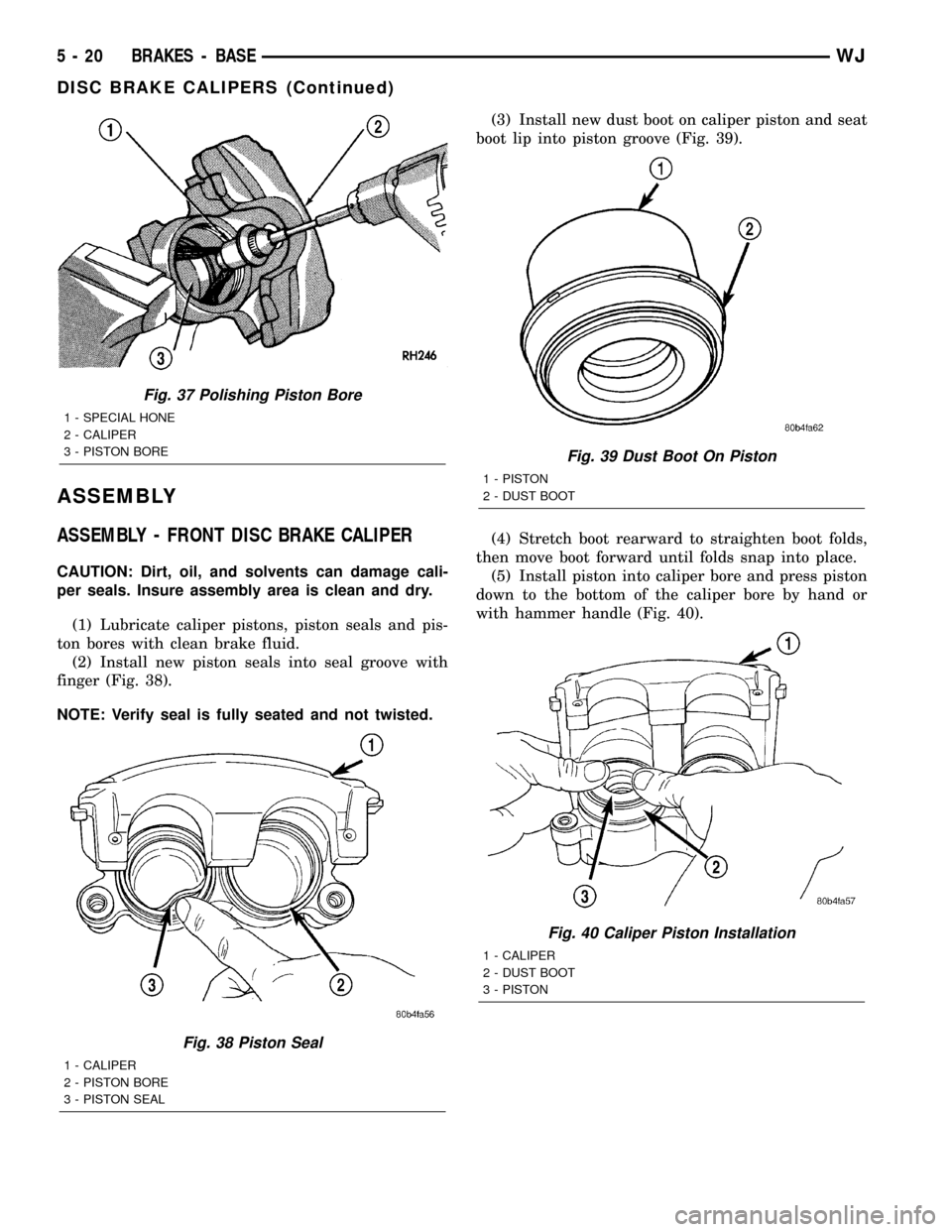
ASSEMBLY
ASSEMBLY - FRONT DISC BRAKE CALIPER
CAUTION: Dirt, oil, and solvents can damage cali-
per seals. Insure assembly area is clean and dry.
(1) Lubricate caliper pistons, piston seals and pis-
ton bores with clean brake fluid.
(2) Install new piston seals into seal groove with
finger (Fig. 38).
NOTE: Verify seal is fully seated and not twisted.(3) Install new dust boot on caliper piston and seat
boot lip into piston groove (Fig. 39).
(4) Stretch boot rearward to straighten boot folds,
then move boot forward until folds snap into place.
(5) Install piston into caliper bore and press piston
down to the bottom of the caliper bore by hand or
with hammer handle (Fig. 40).
Fig. 37 Polishing Piston Bore
1 - SPECIAL HONE
2 - CALIPER
3 - PISTON BORE
Fig. 38 Piston Seal
1 - CALIPER
2 - PISTON BORE
3 - PISTON SEAL
Fig. 39 Dust Boot On Piston
1 - PISTON
2 - DUST BOOT
Fig. 40 Caliper Piston Installation
1 - CALIPER
2 - DUST BOOT
3 - PISTON
5 - 20 BRAKES - BASEWJ
DISC BRAKE CALIPERS (Continued)
Page 196 of 2199
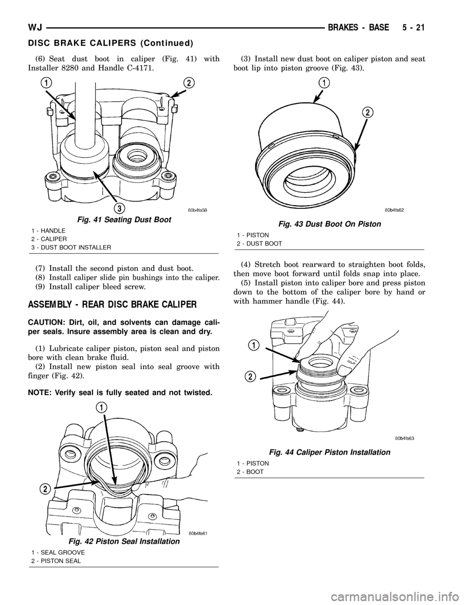
(6) Seat dust boot in caliper (Fig. 41) with
Installer 8280 and Handle C-4171.
(7) Install the second piston and dust boot.
(8)
Install caliper slide pin bushings into the caliper.
(9) Install caliper bleed screw.
ASSEMBLY - REAR DISC BRAKE CALIPER
CAUTION: Dirt, oil, and solvents can damage cali-
per seals. Insure assembly area is clean and dry.
(1) Lubricate caliper piston, piston seal and piston
bore with clean brake fluid.
(2) Install new piston seal into seal groove with
finger (Fig. 42).
NOTE: Verify seal is fully seated and not twisted.(3) Install new dust boot on caliper piston and seat
boot lip into piston groove (Fig. 43).
(4) Stretch boot rearward to straighten boot folds,
then move boot forward until folds snap into place.
(5) Install piston into caliper bore and press piston
down to the bottom of the caliper bore by hand or
with hammer handle (Fig. 44).
Fig. 41 Seating Dust Boot
1 - HANDLE
2 - CALIPER
3 - DUST BOOT INSTALLER
Fig. 42 Piston Seal Installation
1 - SEAL GROOVE
2 - PISTON SEAL
Fig. 43 Dust Boot On Piston
1 - PISTON
2 - DUST BOOT
Fig. 44 Caliper Piston Installation
1 - PISTON
2 - BOOT
WJBRAKES - BASE 5 - 21
DISC BRAKE CALIPERS (Continued)