Cigarette JEEP GRAND CHEROKEE 2003 WJ / 2.G Workshop Manual
[x] Cancel search | Manufacturer: JEEP, Model Year: 2003, Model line: GRAND CHEROKEE, Model: JEEP GRAND CHEROKEE 2003 WJ / 2.GPages: 2199, PDF Size: 76.01 MB
Page 278 of 2199

TRANSMISSION
TABLE OF CONTENTS
page page
TRANS COOLER
DESCRIPTION.........................55STANDARD PROCEDURE - FLUSHING
COOLERS AND TUBES.................55
TRANS COOLER
DESCRIPTION
An internal high capacity/high efficiency cooler is
used on all vehicles these coolers are an oil-to-coolant
type which consists of plates mounted in the radiator
outlet tank (Fig. 36). Because the internal oil cooler
is so efficient, no auxiliary oil cooler is offered The
cooler is not servicable seperatly from the radiator.
STANDARD PROCEDURE - FLUSHING
COOLERS AND TUBES
When a transmission failure has contaminated the
fluid, the oil cooler(s) must be flushed. The torque
converter must also be replaced. This will insure that
metal particles or sludged oil are not later trans-
ferred back into the reconditioned (or replaced) trans-
mission.
The only recommended procedure for flushing cool-
ers and lines is to use Tool 6906-B Cooler Flusher.
WARNING: WEAR PROTECTIVE EYEWEAR THAT
MEETS THE REQUIREMENTS OF OSHA AND ANSI
Z87.1±1968. WEAR STANDARD INDUSTRIAL RUB-
BER GLOVES.
KEEP LIGHTED CIGARETTES, SPARKS, FLAMES,
AND OTHER IGNITION SOURCES AWAY FROM THE
AREA TO PREVENT THE IGNITION OF COMBUSTI-
BLE LIQUIDS AND GASES. KEEP A CLASS (B) FIRE
EXTINGUISHER IN THE AREA WHERE THE
FLUSHER WILL BE USED.
KEEP THE AREA WELL VENTILATED.
DO NOT LET FLUSHING SOLVENT COME IN CON-
TACT WITH YOUR EYES OR SKIN: IF EYE CONTAM-
INATION OCCURS, FLUSH EYES WITH WATER FOR
15 TO 20 SECONDS. REMOVE CONTAMINATED
CLOTHING AND WASH AFFECTED SKIN WITH
SOAP AND WATER. SEEK MEDICAL ATTENTION.
(1) Remove cover plate filler plug on Tool 6906-B.
Fill reservoir 1/2 to 3/4 full of fresh flushing solution.
Flushing solvents are petroleum based solutions gen-
erally used to clean automatic transmission compo-
nents.DO NOTuse solvents containing acids, water,
gasoline, or any other corrosive liquids.(2) Reinstall filler plug on Tool 6906-B.
(3) Verify pump power switch is turned OFF. Con-
nect red alligator clip to positive (+) battery post.
Connect black (-) alligator clip to a good ground.
(4) Disconnect the cooler lines at the transmission.
NOTE: When flushing transmission cooler and
lines, ALWAYS reverse flush.
NOTE: The converter drainback valve must be
removed and an appropriate replacement hose
installed to bridge the space between the transmis-
sion cooler line and the cooler fitting. Failure to
remove the drainback valve will prevent reverse
flushing the system. A suitable replacement hose
can be found in the adapter kit supplied with the
flushing tool.
(5) Connect the BLUE pressure line to the OUT-
LET (From) cooler line.
(6) Connect the CLEAR return line to the INLET
(To) cooler line
(7) Turn pump ON for two to three minutes to
flush cooler(s) and lines.
(8) Turn pump OFF.
(9) Disconnect CLEAR suction line from reservoir
at cover plate. Disconnect CLEAR return line at
cover plate, and place it in a drain pan.
(10) Turn pump ON for 30 seconds to purge flush-
ing solution from cooler and lines. Turn pump OFF.
(11) Place CLEAR suction line into a one quart
container of MopartATF +4, type 9602, Automatic
Transmission Fluid.
(12) Turn pump ON until all transmission fluid is
removed from the one quart container and lines. This
purges any residual cleaning solvent from the trans-
mission cooler and lines. Turn pump OFF.
(13) Disconnect alligator clips from battery. Recon-
nect flusher lines to cover plate, and remove flushing
adapters from cooler lines.
WJTRANSMISSION 7 - 55
Page 1176 of 2199

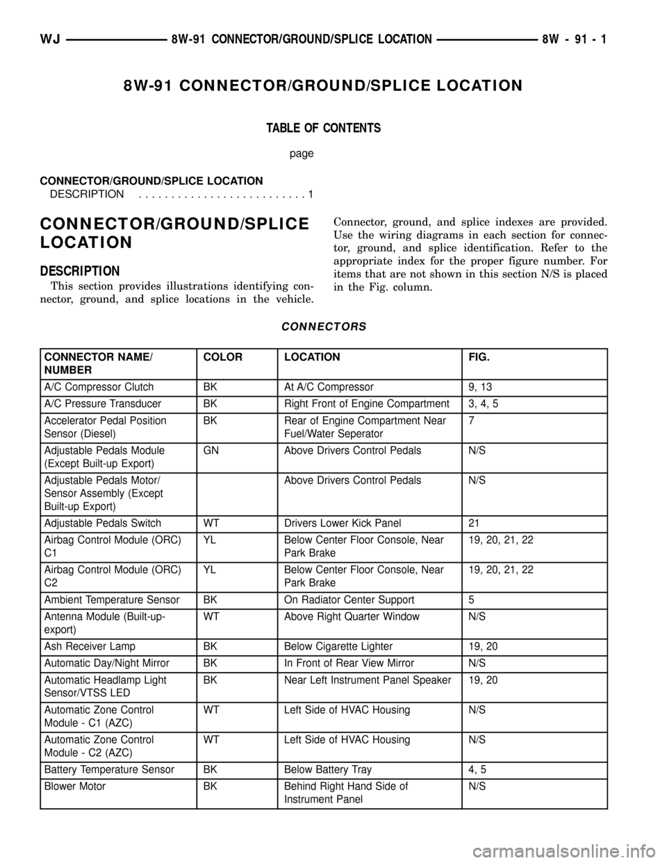
8W-91 CONNECTOR/GROUND/SPLICE LOCATION
TABLE OF CONTENTS
page
CONNECTOR/GROUND/SPLICE LOCATION
DESCRIPTION..........................1
CONNECTOR/GROUND/SPLICE
LOCATION
DESCRIPTION
This section provides illustrations identifying con-
nector, ground, and splice locations in the vehicle.Connector, ground, and splice indexes are provided.
Use the wiring diagrams in each section for connec-
tor, ground, and splice identification. Refer to the
appropriate index for the proper figure number. For
items that are not shown in this section N/S is placed
in the Fig. column.
CONNECTORS
CONNECTOR NAME/
NUMBERCOLOR LOCATION FIG.
A/C Compressor Clutch BK At A/C Compressor 9, 13
A/C Pressure Transducer BK Right Front of Engine Compartment 3, 4, 5
Accelerator Pedal Position
Sensor (Diesel)BK Rear of Engine Compartment Near
Fuel/Water Seperator7
Adjustable Pedals Module
(Except Built-up Export)GN Above Drivers Control Pedals N/S
Adjustable Pedals Motor/
Sensor Assembly (Except
Built-up Export)Above Drivers Control Pedals N/S
Adjustable Pedals Switch WT Drivers Lower Kick Panel 21
Airbag Control Module (ORC)
C1YL Below Center Floor Console, Near
Park Brake19, 20, 21, 22
Airbag Control Module (ORC)
C2YL Below Center Floor Console, Near
Park Brake19, 20, 21, 22
Ambient Temperature Sensor BK On Radiator Center Support 5
Antenna Module (Built-up-
export)WT Above Right Quarter Window N/S
Ash Receiver Lamp BK Below Cigarette Lighter 19, 20
Automatic Day/Night Mirror BK In Front of Rear View Mirror N/S
Automatic Headlamp Light
Sensor/VTSS LEDBK Near Left Instrument Panel Speaker 19, 20
Automatic Zone Control
Module - C1 (AZC)WT Left Side of HVAC Housing N/S
Automatic Zone Control
Module - C2 (AZC)WT Left Side of HVAC Housing N/S
Battery Temperature Sensor BK Below Battery Tray 4, 5
Blower Motor BK Behind Right Hand Side of
Instrument PanelN/S
WJ8W-91 CONNECTOR/GROUND/SPLICE LOCATION 8W - 91 - 1