Evap leak detection pump JEEP GRAND CHEROKEE 2003 WJ / 2.G Workshop Manual
[x] Cancel search | Manufacturer: JEEP, Model Year: 2003, Model line: GRAND CHEROKEE, Model: JEEP GRAND CHEROKEE 2003 WJ / 2.GPages: 2199, PDF Size: 76.01 MB
Page 324 of 2199

DESCRIPTION - POWER GROUNDS
The Powertrain Control Module (PCM) has 2 main
grounds. Both of these grounds are referred to as
power grounds. All of the high-current, noisy, electri-
cal devices are connected to these grounds as well as
all of the sensor returns. The sensor return comes
into the sensor return circuit, passes through noise
suppression, and is then connected to the power
ground.
The power ground is used to control ground cir-
cuits for the following PCM loads:
²Generator field winding
²Fuel injectors
²Ignition coil(s)
²Certain relays/solenoids
²Certain sensors
DESCRIPTION - SENSOR RETURN
The Sensor Return circuits are internal to the Pow-
ertrain Control Module (PCM).
Sensor Return provides a low±noise ground refer-
ence for all engine control system sensors. Refer to
Power Grounds for more information.
OPERATION
OPERATION - PCM
(1) Also refer to Modes of Operation.
The PCM operates the fuel system. The PCM is a
pre-programmed, triple microprocessor digital com-
puter. It regulates ignition timing, air-fuel ratio,
emission control devices, charging system, certain
transmission features, speed control, air conditioning
compressor clutch engagement and idle speed. The
PCM can adapt its programming to meet changing
operating conditions.
The PCM receives input signals from various
switches and sensors. Based on these inputs, the
PCM regulates various engine and vehicle operations
through different system components. These compo-
nents are referred to as Powertrain Control Module
(PCM) Outputs. The sensors and switches that pro-
vide inputs to the PCM are considered Powertrain
Control Module (PCM) Inputs.
The PCM adjusts ignition timing based upon
inputs it receives from sensors that react to: engine
rpm, manifold absolute pressure, engine coolant tem-
perature, throttle position, transmission gear selec-
tion (automatic transmission), vehicle speed and the
brake switch.
The PCM adjusts idle speed based on inputs it
receives from sensors that react to: throttle position,
vehicle speed, transmission gear selection, engine
coolant temperature and from inputs it receives from
the air conditioning clutch switch and brake switch.Based on inputs that it receives, the PCM adjusts
ignition coil dwell. The PCM also adjusts the gener-
ator charge rate through control of the generator
field and provides speed control operation.
NOTE: PCM Inputs:
²A/C request
²Auto shutdown (ASD) sense
²Battery temperature
²Battery voltage
²Brake switch
²J1850 bus circuits
²Camshaft position sensor signal
²Crankshaft position sensor
²Data link connections for DRB scan tool
²Engine coolant temperature sensor
²Five volts (primary)
²Five volts (secondary)
²Fuel level
²Generator (battery voltage) output
²Ignition circuit sense (ignition switch in on/off/
crank/run position)
²Intake manifold air temperature sensor
²Leak detection pump (switch) sense (if equipped)
²Manifold absolute pressure (MAP) sensor
²Oil pressure
²Overdrive/override switch
²Oxygen sensors
²Park/neutral switch (auto. trans. only)
²Power ground
²Sensor return
²Signal ground
²Speed control multiplexed single wire input
²Throttle position sensor
²Transmission governor pressure sensor
²Transmission temperature sensor
²Vehicle speed (from ABS module)
NOTE: PCM Outputs:
²A/C clutch relay
²Auto shutdown (ASD) relay
²J1850 (+/-) circuits for: speedometer, voltmeter,
fuel gauge, oil pressure gauge/lamp, engine temp.
gauge and speed control warn. lamp
²Data link connection for DRBIIItscan tool
²EGR valve control solenoid (if equipped)
²EVAP canister purge solenoid
²Fuel injectors
²Fuel pump relay
²Generator field driver (-)
²Generator field driver (+)
²Generator lamp (if equipped)
²Idle air control (IAC) motor
²Ignition coil
²Leak detection pump
WJELECTRONIC CONTROL MODULES 8E - 15
POWERTRAIN CONTROL MODULE (Continued)
Page 672 of 2199

8W-02 COMPONENT INDEX
Component Page
A/C Compressor Clutch................. 8W-42
A/C Pressure Transducer................ 8W-42
Accelerator Pedal Position Sensor......... 8W-30
Accessory Delay Relay.................. 8W-64
Adjustable Pedals..................... 8W-30
Airbags............................. 8W-43
Ambient Temperature Sensor............ 8W-45
Antennas............................ 8W-47
Ash Receiver Lamp.................... 8W-44
Auto Shut Down Relay................. 8W-30
Automatic Day/Night Mirror............. 8W-49
Automatic Headlamp Light Sensor/VTSS
LED.............................. 8W-39
Automatic Zone Control Module.......... 8W-42
Back-Up Lamp Relay................... 8W-51
Battery Temperature Sensor............. 8W-30
Battery............................. 8W-20
Blend Door Motor/Actuator.............. 8W-42
Blower Motor......................... 8W-42
Body Control Module................... 8W-45
Boost Pressure Sensor.................. 8W-30
Brake Lamp Switch.................... 8W-33
Camshaft Position Sensor............... 8W-30
Capacitors........................... 8W-30
Cargo Lamp.......................... 8W-44
Center High Mounted Stop Lamp......... 8W-51
Cigar Lighter......................... 8W-41
Circuit Breakers...................... 8W-12
Clockspring.................. 8W-33, 41, 43, 47
Coil On Plugs......................... 8W-30
Coil Rail............................. 8W-30
Combination Flasher................... 8W-52
Compact Disc Changer.................. 8W-47
Controller Antilock Brake............... 8W-35
Coolant Level Sensor................... 8W-45
Courtesy Lamps....................... 8W-44
Crankcase Heater..................... 8W-30
Crankshaft Position Sensor.............. 8W-30
Cylinder Lock Switches................. 8W-61
Data Link Connector................... 8W-18
Diagnostic Junction Port................ 8W-18
EGR Solenoid......................... 8W-30
Electric Brake........................ 8W-54
Electronic Speed Control Servo........... 8W-33
Engine Control Module................. 8W-30
Engine Coolant Temperature Sensor...... 8W-30
Engine Oil Pressure Sensor.............. 8W-30
Engine Starter Motor................... 8W-21
EVAP/Purge Solenoid................... 8W-30
Fog Lamps........................ 8W-50, 51
Fuel Injectors......................... 8W-30
Fuel Pressure Sensor................... 8W-30Component Page
Fuel Pressure Solenoid................. 8W-30
Fuel Pump........................... 8W-30
Fuel Tank Module..................... 8W-30
Fuses............................ 8W-10, 12
Fusible Link....................... 8W-10, 20
Grounds............................. 8W-15
Generator......................... 8W-20, 30
Glove Box Lamp...................... 8W-44
Glow Plugs........................... 8W-30
Headlamp Leveling Motor............... 8W-50
Heated Seats......................... 8W-63
High Beam Headlamps................. 8W-50
Hood Ajar Switch...................... 8W-39
Horns............................... 8W-41
Hydraulic Cooling Module............ 8W-30, 42
Idle Air Control Motor.................. 8W-30
Ignition Switch....................... 8W-10
Impact Sensors....................... 8W-43
Input Speed Sensor.................... 8W-31
Instrument Cluster.................... 8W-40
Intake Air Temperature Sensor........... 8W-30
Intake Port Swirl Actuator.............. 8W-30
Intrusion Transceiver Module............ 8W-49
Junction Block........................ 8W-12
Knock Sensor......................... 8W-30
Lamp Assemblies................... 8W-51, 52
Leak Detection Pump.................. 8W-30
License Lamps........................ 8W-51
Liftgate............................. 8W-61
Line Pressure Sensor................... 8W-31
Low Beam Headlamps.................. 8W-50
Low Beam Relay...................... 8W-50
Low Beam/Daytime Running Lamp Relay . . . 8W-50
Lumbar Motor........................ 8W-63
Lumbar Switch....................... 8W-63
Manifold Absolute Pressure Sensor........ 8W-30
Manual Temperature Control............. 8W-42
Mass Air Flow Sensor.................. 8W-30
Memory Set Switch................. 8W-62, 63
Mode Door Motor/Actuator............... 8W-42
Multi-Function Switch............... 8W-50, 53
Output Speed Sensor................... 8W-31
Overhead Map/Courtesy Lamp........... 8W-44
Oxygen Sensors....................... 8W-30
Park Brake Switch..................... 8W-40
Park Lamp........................... 8W-50
Park/Neutral Position Switch............ 8W-31
Park/Turn Signal Lamps................ 8W-50
Power Amplifier....................... 8W-47
Power Connector...................... 8W-41
Power Distribution Center............... 8W-10
Power Mirrors........................ 8W-62
WJ8W-02 COMPONENT INDEX 8W - 02 - 1
Page 782 of 2199

8W-30 FUEL/IGNITION SYSTEM
Component Page
A/C Compressor Clutch Relay . . . 8W-30-23, 35, 39, 41, 42
A/C Pressure Transducer........ 8W-30-21, 42, 45, 31
Accelerator Pedal Position Sensor........ 8W-30-37, 48
Adjustable Pedals Module................ 8W-30-33
Adjustable Pedals Motor/Sensor Assembly.... 8W-30-33
Adjustable Pedals Switch................ 8W-30-33
Auto Shut Down Relay...... 8W-30-8, 9, 12, 24, 25, 26,
27, 28, 29, 30, 35, 39, 41
Battery Temperature Sensor.......... 8W-30-2, 11, 50
Body Control Module................... 8W-30-46
Boost Pressure Sensor.................. 8W-30-45
Brake Lamp Switch.............. 8W-30-4, 5, 32, 51
Camshaft Position Sensor........ 8W-30-18, 19, 20, 49
Capacitor........................... 8W-30-12
Capacitor No. 1....................... 8W-30-16
Capacitor No. 2....................... 8W-30-17
Clockspring...................... 8W-30-4, 5, 38
Coil On Plug No. 1.................... 8W-30-17
Coil On Plug No. 2.................... 8W-30-16
Coil On Plug No. 3.................... 8W-30-17
Coil On Plug No. 4.................... 8W-30-16
Coil On Plug No. 5.................... 8W-30-17
Coil On Plug No. 6.................... 8W-30-16
Coil On Plug No. 7.................... 8W-30-17
Coil On Plug No. 8.................... 8W-30-16
Coil Rail............................ 8W-30-12
Controller Antilock Brake........... 8W-30-2, 36, 51
Crankcase Heater..................... 8W-30-35
Crankshaft Position Sensor....... 8W-30-18, 19, 20, 49
Data Link Connector............... 8W-30-6, 7, 46
Diagnostic Junction Port.......... 8W-30-6, 7, 33, 46
EGR Solenoid........................ 8W-30-50
Electronic Speed Control Servo........... 8W-30-4, 5
Engine Control Module.... 8W-30-34, 35, 36, 37, 38, 39,
40, 41, 42, 43, 44, 45,
46, 47, 48, 49, 50, 51
Engine Coolant Temperature Sensor . . . 8W-30-21, 22, 47
Engine Oil Pressure Sensor......... 8W-30-21, 22, 45
Engine Starter Motor Relay......... 8W-30-18, 19, 39
EVAP/Purge Solenoid.................. 8W-30-4, 5
Fuel Injector No. 1............... 8W-30-13, 15, 44
Fuel Injector No. 2............... 8W-30-13, 14, 44
Fuel Injector No. 3............... 8W-30-13, 15, 44
Fuel Injector No. 4............... 8W-30-13, 14, 44
Fuel Injector No. 5............... 8W-30-13, 15, 44
Fuel Injector No. 6.................. 8W-30-13, 14
Fuel Injector No. 7..................... 8W-30-15
Fuel Injector No. 8..................... 8W-30-14
Fuel Pressure Sensor................... 8W-30-37
Fuel Pressure Solenoid.................. 8W-30-47
Fuel Pump Module.................... 8W-30-10
Fuel Pump Relay.................. 8W-30-8, 9, 10
Fuel Tank Module..................... 8W-30-45
Fuse 6........................... 8W-30-8, 42
Fuse 10............................ 8W-30-33
Fuse 11............................ 8W-30-43
Fuse 12......................... 8W-30-8, 9, 40
Fuse 13............................ 8W-30-41
Fuse 16 . . 8W-30-24, 25, 26, 27, 28, 29, 30, 35, 37, 39, 41
Component Page
Fuse 19............................. 8W-30-9
Fuse 21......................... 8W-30-4, 5, 32
Fuse 22............................ 8W-30-34
Fuse 23............................ 8W-30-39
Fuse 24............................. 8W-30-9
Fuse 26..................... 8W-30-8, 12, 41, 47
Fuse 31............................ 8W-30-39
G103....................... 8W-30-8, 34, 39, 46
G104......................... 8W-30-26, 27, 30
G105........................... 8W-30-35, 39
G108........................... 8W-30-23, 43
G123.............................. 8W-30-50
G300............................ 8W-30-4, 33
G301............................ 8W-30-5, 10
Generator...................... 8W-30-3, 23, 35
Glow Plug No. 1...................... 8W-30-42
Glow Plug No. 2...................... 8W-30-43
Glow Plug No. 3...................... 8W-30-42
Glow Plug No. 4...................... 8W-30-43
Glow Plug No. 5...................... 8W-30-42
Glow Plug Relay No. 1............. 8W-30-35, 42, 43
Glow Plug Relay No. 2............. 8W-30-35, 42, 43
Hydraulic Cooling Module . . . 8W-30-3, 24, 25, 30, 31, 43
Idle Air Control Motor.................. 8W-30-20
Intake Air Temperature Sensor....... 8W-30-21, 22, 38
Intake Port Swirl Actuator............... 8W-30-39
Junction Block......... 8W-30-4, 5, 8, 9, 32, 33, 39, 40
Knock Sensor........................ 8W-30-11
Leak Detection Pump................... 8W-30-23
Manifold Absolute Pressure Sensor.... 8W-30-20, 21, 22
Mass Air Flow Sensor.................. 8W-30-37
Output Speed Sensor.................... 8W-30-2
Oxygen Sensor 1/1 Upstream...... 8W-30-25, 26, 28, 29
Oxygen Sensor 1/2 Downstream.... 8W-30-24, 25, 26, 30
Oxygen Sensor 2/1 Upstream........ 8W-30-27, 28, 29
Oxygen Sensor 2/2 Downstream...... 8W-30-24, 27, 30
Oxygen Sensor Downstream Relay . . 8W-30-24, 26, 27, 30
Park/Neutral Position Switch............. 8W-30-33
Power Distribution Center...... 8W-30-8, 9, 12, 24, 25,
26, 27, 28, 29, 30, 34, 35,
37, 39, 41, 42, 43, 47
Powertrain Control Module . . . 8W-30-2, 3, 4, 5, 6, 7, 8, 9,
10, 11, 12, 13, 14, 15, 16, 17,
18, 19, 20, 21, 22, 23, 24, 25,
26, 27, 28, 29, 30, 31, 32
Shifter Assembly............... 8W-30-2, 32, 38, 40
Speed Control Switch No. 1........... 8W-30-4, 5, 38
Speed Control Switch No. 2........... 8W-30-4, 5, 38
Throttle Position Sensor................. 8W-30-20
Transfer Case Position Sensor........... 8W-30-8, 51
Transmission Control
Module............. 8W-30-6, 7, 20, 23, 32, 36, 40
Transmission Control Relay.............. 8W-30-23
Transmission Solenoid................ 8W-30-3, 21
Transmission Solenoid/TRS Assembly....... 8W-30-33
Viscous/Cabin Heater................... 8W-30-39
Viscous/Cabin Heater Relay...... 8W-30-35, 39, 41, 42
Wastegate Solenoid.................... 8W-30-35
Water In Fuel Sensor................... 8W-30-50
WJ8W-30 FUEL/IGNITION SYSTEM 8W - 30 - 1
Page 1050 of 2199

Component Page
DRIVER SEAT BELT SWITCH........ 8W-80-74
DRIVER SIDE IMPACT SENSOR...... 8W-80-74
EGR SOLENOID (DIESEL)........... 8W-80-74
ELECTRIC BRAKE
(EXCEPT BUILT-UP-EXPORT)...... 8W-80-74
ELECTRONIC SPEED CONTROL
SERVO ......................... 8W-80-74
ENGINE CONTROL MODULE C1
(DIESEL)....................... 8W-80-75
ENGINE CONTROL MODULE C2
(DIESEL)....................... 8W-80-76
ENGINE COOLANT TEMPERATURE
SENSOR (DIESEL)................ 8W-80-77
ENGINE COOLANT TEMPERATURE
SENSOR (GAS)................... 8W-80-77
ENGINE OIL PRESSURE
SENSOR (DIESEL)................ 8W-80-77
ENGINE OIL PRESSURE
SENSOR (GAS)................... 8W-80-78
EVAP/PURGE SOLENOID (GAS)....... 8W-80-78
FRONT POWER OUTLET............ 8W-80-78
FRONT WASHER PUMP............. 8W-80-78
FRONT WIPER MOTOR............. 8W-80-78
FUEL INJECTOR NO. 1 (DIESEL)..... 8W-80-79
FUEL INJECTOR NO. 1 (GAS)........ 8W-80-79
FUEL INJECTOR NO. 2 (DIESEL)..... 8W-80-79
FUEL INJECTOR NO. 2 (GAS)........ 8W-80-79
FUEL INJECTOR NO. 3 (DIESEL)..... 8W-80-79
FUEL INJECTOR NO. 3 (GAS)........ 8W-80-80
FUEL INJECTOR NO. 4 (DIESEL)..... 8W-80-80
FUEL INJECTOR NO. 4 (GAS)........ 8W-80-80
FUEL INJECTOR NO. 5 (DIESEL)..... 8W-80-80
FUEL INJECTOR NO. 5 (GAS)........ 8W-80-81
FUEL INJECTOR NO. 6 (GAS)........ 8W-80-81
FUEL INJECTOR NO. 7 (4.7L)........ 8W-80-81
FUEL INJECTOR NO. 8 (4.7L)........ 8W-80-81
FUEL PRESSURE SENSOR (DIESEL) . . 8W-80-82
FUEL PRESSURE SOLENOID
(DIESEL)....................... 8W-80-82
FUEL PUMP MODULE (GAS)......... 8W-80-82
FUEL TANK MODULE (DIESEL)...... 8W-80-82
GENERATOR (DIESEL).............. 8W-80-82
GENERATOR (GAS)................. 8W-80-83
GLOVE BOX LAMP................. 8W-80-83
HEADLAMP LEVELING SWITCH
(BUILT-UP-EXPORT).............. 8W-80-83
HOOD AJAR SWITCH
(BUILT-UP-EXPORT).............. 8W-80-83
HORN NO. 1....................... 8W-80-83
HORN NO. 2....................... 8W-80-84
HYDRAULIC COOLING MODULE..... 8W-80-84
IDLE AIR CONTROL MOTOR......... 8W-80-84
IGNITION SWITCH C1.............. 8W-80-84
IGNITION SWITCH C2.............. 8W-80-84
INPUT SPEED SENSOR (4.7L)........ 8W-80-85Component Page
INSTRUMENT CLUSTER............ 8W-80-85
INTAKE AIR TEMPERATURE
SENSOR (DIESEL)................ 8W-80-85
INTAKE AIR TEMPERATURE
SENSOR (GAS)................... 8W-80-85
INTAKE PORT SWIRL ACTUATOR
(DIESEL)....................... 8W-80-86
INTRUSION TRANSCEIVER MODULE
(BUILT-UP-EXPORT).............. 8W-80-86
JUNCTION BLOCK BODY
CONTROL MODULE.............. 8W-80-86
JUNCTION BLOCK C1.............. 8W-80-87
JUNCTION BLOCK C2 (LHD)......... 8W-80-88
JUNCTION BLOCK C2 (RHD)......... 8W-80-89
JUNCTION BLOCK C3.............. 8W-80-90
JUNCTION BLOCK C4.............. 8W-80-91
JUNCTION BLOCK C5.............. 8W-80-91
KNOCK SENSOR................... 8W-80-91
LEAK DETECTION PUMP (EXCEPT
BUILT-UP-EXPORT)............... 8W-80-91
LEFT COURTESY LAMP............. 8W-80-91
LEFT DOOR HANDLE COURTESY
LAMP.......................... 8W-80-92
LEFT FOG LAMP................... 8W-80-92
LEFT FRONT DOOR SPEAKER....... 8W-80-92
LEFT FRONT IMPACT SENSOR....... 8W-80-92
LEFT FRONT PARK LAMP........... 8W-80-92
LEFT FRONT PARK/TURN SIGNAL LAMP
(EXCEPT BUILT-UP-EXPORT)...... 8W-80-93
LEFT FRONT SIDE MARKER LAMP
(EXCEPT BUILT-UP-EXPORT)...... 8W-80-93
LEFT FRONT TURN SIGNAL LAMP
(BUILT-UP-EXPORT).............. 8W-80-93
LEFT FRONT WHEEL SPEED
SENSOR........................ 8W-80-93
LEFT HEADLAMP LEVELING MOTOR
(BUILT-UP-EXPORT).............. 8W-80-94
LEFT HIGH BEAM HEADLAMP....... 8W-80-94
LEFT INSTRUMENT PANEL SPEAKER . 8W-80-94
LEFT LIFTGATE AJAR SWITCH....... 8W-80-94
LEFT LOW BEAM HEADLAMP....... 8W-80-94
LEFT MULTI-FUNCTION SWITCH.... 8W-80-95
LEFT REAR DOOR LOCK
MOTOR/AJAR SWITCH............ 8W-80-95
LEFT REAR DOOR SPEAKER......... 8W-80-95
LEFT REAR LAMP ASSEMBLY........ 8W-80-95
LEFT REAR WHEEL SPEED
SENSOR........................ 8W-80-96
LEFT REMOTE RADIO SWITCH...... 8W-80-96
LEFT SIDE REPEATER LAMP
(BUILT-UP-EXPORT).............. 8W-80-96
LEFT VISOR/VANITY LAMP.......... 8W-80-96
LICENSE LAMP NO. 1.............. 8W-80-96
LICENSE LAMP NO. 2.............. 8W-80-97
LIFTGATE FLIP-UP AJAR SWITCH.... 8W-80-97
WJ8W-80 CONNECTOR PIN-OUT 8W - 80 - 3
Page 1157 of 2199
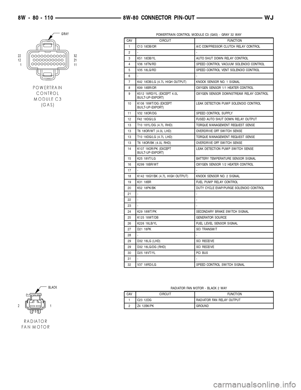
POWERTRAIN CONTROL MODULE C3 (GAS) - GRAY 32 WAY
CAV CIRCUIT FUNCTION
1 C13 18DB/OR A/C COMPRESSOR CLUTCH RELAY CONTROL
2- -
3 K51 18DB/YL AUTO SHUT DOWN RELAY CONTROL
4 V36 18TN/RD SPEED CONTROL VACUUM SOLENOID CONTROL
5 V35 18LG/RD SPEED CONTROL VENT SOLENOID CONTROL
6- -
7 K42 18DB/LG (4.7L HIGH OUTPUT) KNOCK SENSOR NO. 1 SIGNAL
8 K99 18BR/OR OXYGEN SENSOR 1/1 HEATER CONTROL
9 K512 18RD/YL (EXCEPT 4.0L
BUILT-UP-EXPORT)OXYGEN SENSOR DOWNSTREAM RELAY CONTROL
10 K106 18WT/DG (EXCEPT
BUILT-UP-EXPORT)LEAK DETECTION PUMP SOLENOID CONTROL
11 V32 18OR/DG SPEED CONTROL SUPPLY
12 F42 18DG/LG FUSED AUTO SHUT DOWN RELAY OUTPUT
13 T10 18YL/DG (4.7L RHD) TORQUE MANAGEMENT REQUEST SENSE
13 T6 18OR/WT (4.0L LHD) OVERDRIVE OFF SWITCH SENSE
13 T10 18DG/LG (4.7L LHD) TORQUE MANAGEMENT REQUEST SENSE
13 T6 18OR/BK (4.0L RHD) OVERDRIVE OFF SWITCH SENSE
14 K107 18OR/PK (EXCEPT
BUILT-UP-EXPORT)LEAK DETECTION PUMP SWITCH SENSE
15 K25 18VT/LG BATTERY TEMPERATURE SENSOR SIGNAL
16 K299 18BR/WT OXYGEN SENSOR 1/2 HEATER CONTROL
17 - -
18 K142 18GY/BK (4.7L HIGH OUTPUT) KNOCK SENSOR NO. 2 SIGNAL
19 K31 18BR FUEL PUMP RELAY CONTROL
20 K52 18PK/BK DUTY CYCLE EVAP/PURGE SOLENOID CONTROL
21 - -
22 - -
23 - -
24 K29 18WT/PK SECONDARY BRAKE SWITCH SIGNAL
25 K125 18WT/DB GENERATOR SOURCE
26 K226 18LB/YL FUEL LEVEL SENSOR SIGNAL
27 D21 18PK SCI TRANSMIT
28 - -
29 D32 18LG (LHD) SCI RECEIVE
29 D32 18LG/DG (RHD) SCI RECEIVE
30 D25 18VT/YL PCI BUS
31 - -
32 V37 18RD/LG SPEED CONTROL SWITCH SIGNAL
RADIATOR FAN MOTOR - BLACK 2 WAY
CAV CIRCUIT FUNCTION
1 C23 12DG RADIATOR FAN RELAY OUTPUT
2 Z4 12BK/PK GROUND
8W - 80 - 110 8W-80 CONNECTOR PIN-OUTWJ
Page 1426 of 2199

(3) Apply a small amount of clean engine oil to
o-rings.
(4) Position filter/regulator to body and install 2
bolts. Tighten bolts to 3 N´m (30 in. lbs.) torque.
(5) Connect 3 fittings. Refer to Quick-Connect Fit-
tings.
(6) Connect negative battery cable to battery.
(7) Start engine and check for leaks.
FUEL LEVEL SENDING UNIT /
SENSOR
DESCRIPTION
The fuel gauge sending unit (fuel level sensor) is
attached to the side of the fuel pump module. The
sending unit consists of a float, an arm, and a vari-
able resistor track (card).
OPERATION
The fuel pump module has 4 different circuits
(wires). Two of these circuits are used for the fuel
gauge sending unit for fuel gauge operation, and for
certain OBD II emission requirements. The other 2
wires are used for electric fuel pump operation.
For Fuel Gauge Operation:A constant input
voltage source of about 12 volts (battery voltage) is
supplied to the resistor track on the fuel gauge send-
ing unit. This is fed directly from the Powertrain
Control Module (PCM).NOTE: For diagnostic pur-
poses, this 12V power source can only be veri-fied with the circuit opened (fuel pump module
electrical connector unplugged). With the con-
nectors plugged, output voltages will vary from
about 0.6 volts at FULL, to about 8.6 volts at
EMPTY (about 8.6 volts at EMPTY for Jeep
models, and about 7.0 volts at EMPTY for
Dodge Truck models).The resistor track is used to
vary the voltage (resistance) depending on fuel tank
float level. As fuel level increases, the float and arm
move up, which decreases voltage. As fuel level
decreases, the float and arm move down, which
increases voltage. The varied voltage signal is
returned back to the PCM through the sensor return
circuit.
Both of the electrical circuits between the fuel
gauge sending unit and the PCM are hard-wired (not
multi-plexed). After the voltage signal is sent from
the resistor track, and back to the PCM, the PCM
will interpret the resistance (voltage) data and send
a message across the multi-plex bus circuits to the
instrument panel cluster. Here it is translated into
the appropriate fuel gauge level reading. Refer to
Instrument Panel for additional information.
For OBD II Emission Monitor Requirements:
The PCM will monitor the voltage output sent from
the resistor track on the sending unit to indicate fuel
level. The purpose of this feature is to prevent the
OBD II system from recording/setting false misfire
and fuel system monitor diagnostic trouble codes.
The feature is activated if the fuel level in the tank
is less than approximately 15 percent of its rated
capacity. If equipped with a Leak Detection Pump
(EVAP system monitor), this feature will also be acti-
vated if the fuel level in the tank is more than
approximately 85 percent of its rated capacity.
DIAGNOSIS AND TESTING - FUEL LEVEL
SENDING UNIT
The fuel level sending unit contains a variable
resistor (track). As the float moves up or down, elec-
trical resistance will change. Refer to Instrument
Panel and Gauges for Fuel Gauge testing. To test the
gauge sending unit only, it must be removed from
vehicle. The unit is part of the fuel pump module.
Refer to Fuel Pump Module Removal/Installation for
procedures. Measure the resistance across the send-
ing unit terminals. With float in up position, resis-
tance should be 20 ohms (+/- 5%). With float in down
position, resistance should be 270 ohms (+/- 5%).
REMOVAL
The fuel gauge sending unit (fuel level sensor) and
float assembly is located on the side of fuel pump
module (Fig. 6). The fuel pump module is located
within the fuel tank.
Fig. 5 Fuel Filter/Fuel Pressure Regulator Removal/
Installation
1 - FUEL FILTER/FUEL PRESSURE REGULATOR
2 - MOUNTING BOLTS (2)
WJFUEL DELIVERY 14 - 7
FUEL FILTER/PRESSURE REGULATOR (Continued)
Page 1438 of 2199

(14) Install air tube (or duct) at top of throttle
body.
(15) Install fuel tank cap.
(16) Connect negative battery cable to battery.
(17) Start engine and check for fuel leaks.
FUEL TANK
DESCRIPTION
The fuel tank is constructed of a plastic material.
Its main functions are for fuel storage and for place-
ment of the fuel pump module and certain ORVR
components.
OPERATION
All models pass a full 360 degree rollover test
without fuel leakage. To accomplish this, fuel and
vapor flow controls are required for all fuel tank con-
nections.
A fuel tank check valve(s) is mounted into the top
of the fuel tank (or pump module). Refer to Fuel
Tank Check Valve for additional information.
An evaporation control system is connected to the
check valve(s) to reduce emissions of fuel vapors into
the atmosphere. When fuel evaporates from the fuel
tank, vapors pass through vent hoses or tubes to a
charcoal canister where they are temporarily held.
When the engine is running, the vapors are drawn
into the intake manifold. Certain models are also
equipped with a self-diagnosing system using a Leak
Detection Pump (LDP). Refer to Emission Control
System for additional information.
Refer to ORVR for On-Board Refueling Vapor
Recovery system information.
REMOVAL
WARNING: THE FUEL SYSTEM IS UNDER CON-
STANT FUEL PRESSURE EVEN WITH ENGINE OFF.
PRESSURE MUST BE RELEASED BEFORE SERVIC-
ING FUEL TANK.
Two different procedures may be used to drain fuel
tank (through ORVR control valve opening at top of
fuel tank, or using DRB scan tool). The quickest is
draining through ORVR control valve opening at top
of fuel tank (Fig. 26).
As an alternative procedure, the electric fuel pump
may be activated allowing tank to be drained at fuel
rail connection. Refer to DRB scan tool for fuel pump
activation procedures. Before disconnecting fuel line
at fuel rail, release fuel pressure. Refer to the Fuel
System Pressure Release Procedure for procedures.
Attach end of Special Adapter Hose Tool number
6539 at fuel rail disconnection. Position opposite end
of 6539 to an approved gasoline draining station.Activate fuel pump with DRB and drain tank until
empty.
If electric fuel pump is not operating, tankMUST
be drained through ORVR control valve opening at
top of fuel tank (Fig. 26).
(1) Release fuel system pressure. Refer to Fuel
System Pressure Release Procedure.
(2) Disconnect negative battery cable at battery.
(3) Raise and support vehicle.
(4) Remove left rear wheel/tire.
CAUTION: HANDLE EVAP, LDP AND ORVR VAPOR /
VACUUM LINES VERY CAREFULLY. THESE LINES
AND HOSES MUST BE FIRMLY CONNECTED.
CHECK THE VAPOR/VACUUM LINES AT THE LDP,
LDP FILTER, EVAP CANISTER, EVAP CANISTER
PURGE SOLENOID AND ORVR COMPONENTS FOR
DAMAGE OR LEAKS. IF A LEAK IS PRESENT, A
DIAGNOSTIC TROUBLE CODE (DTC) MAY BE SET.
(5) Clean top of fuel tank at ORVR control valve
(Fig. 26) or (Fig. 27).
(6) Press release tab in direction of arrow in (Fig.
27) and remove ORVR control valve lock ring
(counter-clockwise). Lift up ORVR control slightly.
Using an approved gasoline draining station, drain
tank until empty through this opening.
(7) Remove stone shield behind left/rear wheel
(Fig. 28). Drill out plastic rivets for removal.
(8) Remove 3 LDP mounting bolts (Fig. 29).
(9) Remove support bracket brace bolt (Fig. 30).
(10) Loosen, but do not remove 2 support bracket
nuts at frame rail (Fig. 29).
(11) To separate and lower front section of two-
piece support bracket, remove 3 attaching bolts on
bottom of support bracket (Fig. 30). While lowering
support bracket, disconnect LDP wiring clip (Fig. 31).
(12) Remove hose clamp (Fig. 32) and remove fuel
fill hose from fuel fill tube.
(13) Cut and discard tie wrap from axle vent hose
(Fig. 32).
(14) Disconnect fuel vent hose from fuel vent tube
(Fig. 32).
(15) Disconnect ORVR hose elbow (Fig. 33) at top
of EVAP canister.
(16) Place hydraulic jack to bottom of fuel tank.
(17) Remove fuel tank-to-rear bumper fascia clips
(Fig. 34).
(18) Remove fuel tank heat shield mounting bolts
(Fig. 35).
CAUTION: To protect fuel tank from exhaust heat,
shield must re-installed after tank installation.
WARNING: PLACE SHOP TOWEL AROUND FUEL
LINES TO CATCH ANY EXCESS FUEL.
WJFUEL DELIVERY 14 - 19
FUEL RAIL (Continued)
Page 2168 of 2199
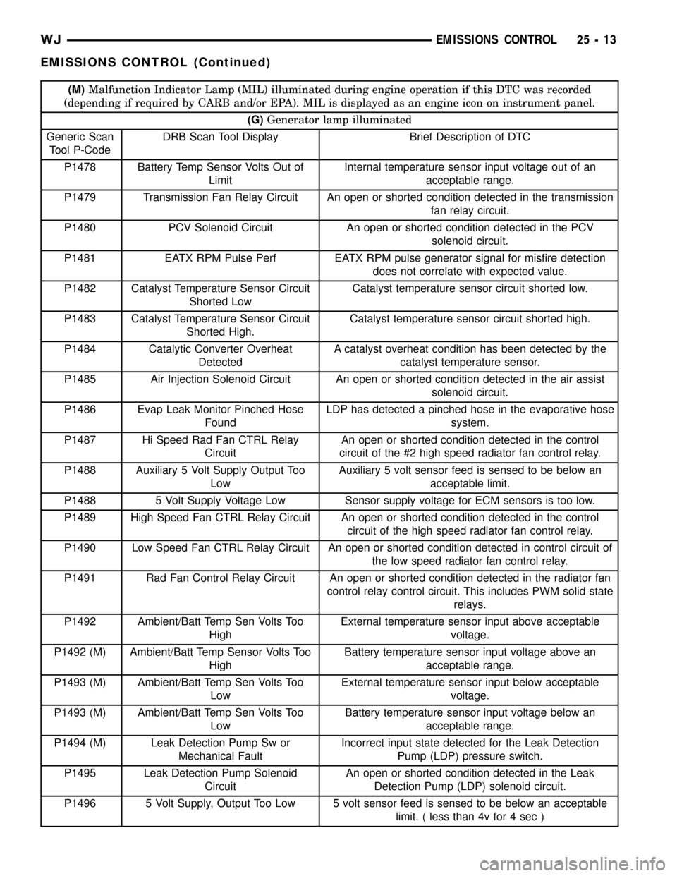
(M)Malfunction Indicator Lamp (MIL) illuminated during engine operation if this DTC was recorded
(depending if required by CARB and/or EPA). MIL is displayed as an engine icon on instrument panel.
(G)Generator lamp illuminated
Generic Scan
Tool P-CodeDRB Scan Tool Display Brief Description of DTC
P1478 Battery Temp Sensor Volts Out of
LimitInternal temperature sensor input voltage out of an
acceptable range.
P1479 Transmission Fan Relay Circuit An open or shorted condition detected in the transmission
fan relay circuit.
P1480 PCV Solenoid Circuit An open or shorted condition detected in the PCV
solenoid circuit.
P1481 EATX RPM Pulse Perf EATX RPM pulse generator signal for misfire detection
does not correlate with expected value.
P1482 Catalyst Temperature Sensor Circuit
Shorted LowCatalyst temperature sensor circuit shorted low.
P1483 Catalyst Temperature Sensor Circuit
Shorted High.Catalyst temperature sensor circuit shorted high.
P1484 Catalytic Converter Overheat
DetectedA catalyst overheat condition has been detected by the
catalyst temperature sensor.
P1485 Air Injection Solenoid Circuit An open or shorted condition detected in the air assist
solenoid circuit.
P1486 Evap Leak Monitor Pinched Hose
FoundLDP has detected a pinched hose in the evaporative hose
system.
P1487 Hi Speed Rad Fan CTRL Relay
CircuitAn open or shorted condition detected in the control
circuit of the #2 high speed radiator fan control relay.
P1488 Auxiliary 5 Volt Supply Output Too
LowAuxiliary 5 volt sensor feed is sensed to be below an
acceptable limit.
P1488 5 Volt Supply Voltage Low Sensor supply voltage for ECM sensors is too low.
P1489 High Speed Fan CTRL Relay Circuit An open or shorted condition detected in the control
circuit of the high speed radiator fan control relay.
P1490 Low Speed Fan CTRL Relay Circuit An open or shorted condition detected in control circuit of
the low speed radiator fan control relay.
P1491 Rad Fan Control Relay Circuit An open or shorted condition detected in the radiator fan
control relay control circuit. This includes PWM solid state
relays.
P1492 Ambient/Batt Temp Sen Volts Too
HighExternal temperature sensor input above acceptable
voltage.
P1492 (M) Ambient/Batt Temp Sensor Volts Too
HighBattery temperature sensor input voltage above an
acceptable range.
P1493 (M) Ambient/Batt Temp Sen Volts Too
LowExternal temperature sensor input below acceptable
voltage.
P1493 (M) Ambient/Batt Temp Sen Volts Too
LowBattery temperature sensor input voltage below an
acceptable range.
P1494 (M) Leak Detection Pump Sw or
Mechanical FaultIncorrect input state detected for the Leak Detection
Pump (LDP) pressure switch.
P1495 Leak Detection Pump Solenoid
CircuitAn open or shorted condition detected in the Leak
Detection Pump (LDP) solenoid circuit.
P1496 5 Volt Supply, Output Too Low 5 volt sensor feed is sensed to be below an acceptable
limit. ( less than 4v for 4 sec )
WJEMISSIONS CONTROL 25 - 13
EMISSIONS CONTROL (Continued)
Page 2172 of 2199

DESCRIPTION - TASK MANAGER
The PCM is responsible for efficiently coordinating
the operation of all the emissions-related compo-
nents. The PCM is also responsible for determining if
the diagnostic systems are operating properly. The
software designed to carry out these responsibilities
is referred to as the 'Task Manager'.
DESCRIPTION - MONITORED SYSTEMS
There are new electronic circuit monitors that
check fuel, emission, engine and ignition perfor-
mance. These monitors use information from various
sensor circuits to indicate the overall operation of the
fuel, engine, ignition and emission systems and thus
the emissions performance of the vehicle.
The fuel, engine, ignition and emission systems
monitors do not indicate a specific component prob-
lem. They do indicate that there is an implied prob-
lem within one of the systems and that a specific
problem must be diagnosed.
If any of these monitors detect a problem affecting
vehicle emissions, the Malfunction Indicator Lamp
(MIL) will be illuminated. These monitors generate
Diagnostic Trouble Codes that can be displayed with
the MIL or a scan tool.
The following is a list of the system monitors:
²Misfire Monitor
²Fuel System Monitor
²Oxygen Sensor Monitor
²Oxygen Sensor Heater Monitor
²Catalyst Monitor
²Leak Detection Pump Monitor (if equipped)
All these system monitors require two consecutive
trips with the malfunction present to set a fault.
Refer to the appropriate Powertrain Diagnos-
tics Procedures manual for diagnostic proce-
dures.
The following is an operation and description of
each system monitor:
OXYGEN SENSOR (O2S) MONITOR
Effective control of exhaust emissions is achieved
by an oxygen feedback system. The most important
element of the feedback system is the O2S. The O2S
is located in the exhaust path. Once it reaches oper-
ating temperature 300É to 350ÉC (572É to 662ÉF), the
sensor generates a voltage that is inversely propor-
tional to the amount of oxygen in the exhaust. The
information obtained by the sensor is used to calcu-
late the fuel injector pulse width. This maintains a
14.7 to 1 Air Fuel (A/F) ratio. At this mixture ratio,
the catalyst works best to remove hydrocarbons (HC),
carbon monoxide (CO) and nitrogen oxide (NOx) from
the exhaust.
The O2S is also the main sensing element for the
Catalyst and Fuel Monitors.The O2S can fail in any or all of the following
manners:
²slow response rate
²reduced output voltage
²dynamic shift
²shorted or open circuits
Response rate is the time required for the sensor to
switch from lean to rich once it is exposed to a richer
than optimum A/F mixture or vice versa. As the sen-
sor starts malfunctioning, it could take longer to
detect the changes in the oxygen content of the
exhaust gas.
The output voltage of the O2S ranges from 0 to 1
volt. A good sensor can easily generate any output
voltage in this range as it is exposed to different con-
centrations of oxygen. To detect a shift in the A/F
mixture (lean or rich), the output voltage has to
change beyond a threshold value. A malfunctioning
sensor could have difficulty changing beyond the
threshold value.
OXYGEN SENSOR HEATER MONITOR
If there is an oxygen sensor (O2S) shorted to volt-
age DTC, as well as a O2S heater DTC, the O2S
fault MUST be repaired first. Before checking the
O2S fault, verify that the heater circuit is operating
correctly.
Effective control of exhaust emissions is achieved
by an oxygen feedback system. The most important
element of the feedback system is the O2S. The O2S
is located in the exhaust path. Once it reaches oper-
ating temperature 300É to 350ÉC (572 É to 662ÉF), the
sensor generates a voltage that is inversely propor-
tional to the amount of oxygen in the exhaust. The
information obtained by the sensor is used to calcu-
late the fuel injector pulse width. This maintains a
14.7 to 1 Air Fuel (A/F) ratio. At this mixture ratio,
the catalyst works best to remove hydrocarbons (HC),
carbon monoxide (CO) and nitrogen oxide (NOx) from
the exhaust.
The voltage readings taken from the O2S sensor
are very temperature sensitive. The readings are not
accurate below 300ÉC. Heating of the O2S sensor is
done to allow the engine controller to shift to closed
loop control as soon as possible. The heating element
used to heat the O2S sensor must be tested to ensure
that it is heating the sensor properly.
The O2S sensor circuit is monitored for a drop in
voltage. The sensor output is used to test the heater
by isolating the effect of the heater element on the
O2S sensor output voltage from the other effects.
LEAK DETECTION PUMP MONITOR (IF EQUIPPED)
The leak detection assembly incorporates two pri-
mary functions: it must detect a leak in the evapora-
WJEMISSIONS CONTROL 25 - 17
EMISSIONS CONTROL (Continued)
Page 2173 of 2199

tive system and seal the evaporative system so the
leak detection test can be run.
The primary components within the assembly are:
A three port solenoid that activates both of the func-
tions listed above; a pump which contains a switch,
two check valves and a spring/diaphragm, a canister
vent valve (CVV) seal which contains a spring loaded
vent seal valve.
Immediately after a cold start, between predeter-
mined temperature thresholds limits, the three port
solenoid is briefly energized. This initializes the
pump by drawing air into the pump cavity and also
closes the vent seal. During non test conditions the
vent seal is held open by the pump diaphragm
assembly which pushes it open at the full travel posi-
tion. The vent seal will remain closed while the
pump is cycling due to the reed switch triggering of
the three port solenoid that prevents the diaphragm
assembly from reaching full travel. After the brief
initialization period, the solenoid is de-energized
allowing atmospheric pressure to enter the pump
cavity, thus permitting the spring to drive the dia-
phragm which forces air out of the pump cavity and
into the vent system. When the solenoid is energized
and de energized, the cycle is repeated creating flow
in typical diaphragm pump fashion. The pump is con-
trolled in 2 modes:
Pump Mode:The pump is cycled at a fixed rate to
achieve a rapid pressure build in order to shorten the
overall test length.
Test Mode:The solenoid is energized with a fixed
duration pulse. Subsequent fixed pulses occur when
the diaphragm reaches the Switch closure point.
The spring in the pump is set so that the system
will achieve an equalized pressure of about 7.5º
water. The cycle rate of pump strokes is quite rapid
as the system begins to pump up to this pressure. As
the pressure increases, the cycle rate starts to drop
off. If there is no leak in the system, the pump would
eventually stop pumping at the equalized pressure. If
there is a leak, it will continue to pump at a rate rep-
resentative of the flow characteristic of the size of the
leak. From this information we can determine if the
leak is larger than the required detection limit (cur-
rently set at .040º orifice by CARB). If a leak is
revealed during the leak test portion of the test, the
test is terminated at the end of the test mode and no
further system checks will be performed.
After passing the leak detection phase of the test,
system pressure is maintained by turning on the
LDP's solenoid until the purge system is activated.
Purge activation in effect creates a leak. The cycle
rate is again interrogated and when it increases due
to the flow through the purge system, the leak check
portion of the diagnostic is complete.The canister vent valve will unseal the system
after completion of the test sequence as the pump
diaphragm assembly moves to the full travel position.
Evaporative system functionality will be verified by
using the stricter evap purge flow monitor. At an
appropriate warm idle the LDP will be energized to
seal the canister vent. The purge flow will be clocked
up from some small value in an attempt to see a
shift in the 02 control system. If fuel vapor, indicated
by a shift in the 02 control, is present the test is
passed. If not, it is assumed that the purge system is
not functioning in some respect. The LDP is again
turned off and the test is ended.
MISFIRE MONITOR
Excessive engine misfire results in increased cata-
lyst temperature and causes an increase in HC emis-
sions. Severe misfires could cause catalyst damage.
To prevent catalytic convertor damage, the PCM
monitors engine misfire.
The Powertrain Control Module (PCM) monitors
for misfire during most engine operating conditions
(positive torque) by looking at changes in the crank-
shaft speed. If a misfire occurs the speed of the
crankshaft will vary more than normal.
FUEL SYSTEM MONITOR
To comply with clean air regulations, vehicles are
equipped with catalytic converters. These converters
reduce the emission of hydrocarbons, oxides of nitro-
gen and carbon monoxide. The catalyst works best
when the Air Fuel (A/F) ratio is at or near the opti-
mum of 14.7 to 1.
The PCM is programmed to maintain the optimum
air/fuel ratio of 14.7 to 1. This is done by making
short term corrections in the fuel injector pulse width
based on the O2S sensor output. The programmed
memory acts as a self calibration tool that the engine
controller uses to compensate for variations in engine
specifications, sensor tolerances and engine fatigue
over the life span of the engine. By monitoring the
actual fuel-air ratio with the O2S sensor (short term)
and multiplying that with the program long-term
(adaptive) memory and comparing that to the limit,
it can be determined whether it will pass an emis-
sions test. If a malfunction occurs such that the PCM
cannot maintain the optimum A/F ratio, then the
MIL will be illuminated.
CATALYST MONITOR
To comply with clean air regulations, vehicles are
equipped with catalytic converters. These converters
reduce the emission of hydrocarbons, oxides of nitro-
gen and carbon monoxide.
Normal vehicle miles or engine misfire can cause a
catalyst to decay. This can increase vehicle emissions
25 - 18 EMISSIONS CONTROLWJ
EMISSIONS CONTROL (Continued)