Failure JEEP GRAND CHEROKEE 2003 WJ / 2.G Workshop Manual
[x] Cancel search | Manufacturer: JEEP, Model Year: 2003, Model line: GRAND CHEROKEE, Model: JEEP GRAND CHEROKEE 2003 WJ / 2.GPages: 2199, PDF Size: 76.01 MB
Page 5 of 2199
FASTENER USAGE
DESCRIPTION - FASTENER USAGE
WARNING: USE OF AN INCORRECT FASTENER
MAY RESULT IN COMPONENT DAMAGE OR PER-
SONAL INJURY.
Fasteners and torque specifications references in
this Service Manual are identified in metric and SAE
format.
During any maintenance or repair procedures, it is
important to salvage all fasteners (nuts, bolts, etc.)
for reassembly. If the fastener is not salvageable, a
fastener of equivalent specification must be used.
THREADED HOLE REPAIR
DESCRIPTION - THREADED HOLE REPAIR
Most stripped threaded holes can be repaired using
a Helicoilt. Follow the vehicle or Helicoiltrecommen-
dations for application and repair procedures.
INTERNATIONAL SYMBOLS
DESCRIPTION - INTERNATIONAL SYMBOLS
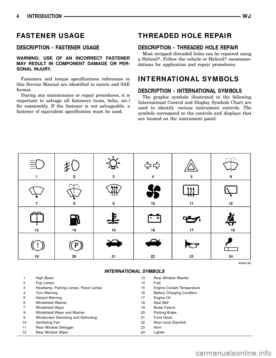
The graphic symbols illustrated in the following
International Control and Display Symbols Chart are
used to identify various instrument controls. The
symbols correspond to the controls and displays that
are located on the instrument panel.
INTERNATIONAL SYMBOLS
1 High Beam 13 Rear Window Washer
2 Fog Lamps 14 Fuel
3 Headlamp, Parking Lamps, Panel Lamps 15 Engine Coolant Temperature
4 Turn Warning 16 Battery Charging Condition
5 Hazard Warning 17 Engine Oil
6 Windshield Washer 18 Seat Belt
7 Windshield Wiper 19 Brake Failure
8 Windshield Wiper and Washer 20 Parking Brake
9 Windscreen Demisting and Defrosting 21 Front Hood
10 Ventilating Fan 22 Rear hood (Decklid)
11 Rear Window Defogger 23 Horn
12 Rear Window Wiper 24 Lighter
4 INTRODUCTIONWJ
Page 80 of 2199
AXLE SHAFT SEALS
REMOVAL
(1) Raise and support vehicle.
(2) Remove axle shafts.
(3) Remove differential assembly.
(4) Remove inner axle shaft seals with a pry bay.
INSTALLATION
(1) Remove any sealer remaining from original
seals.
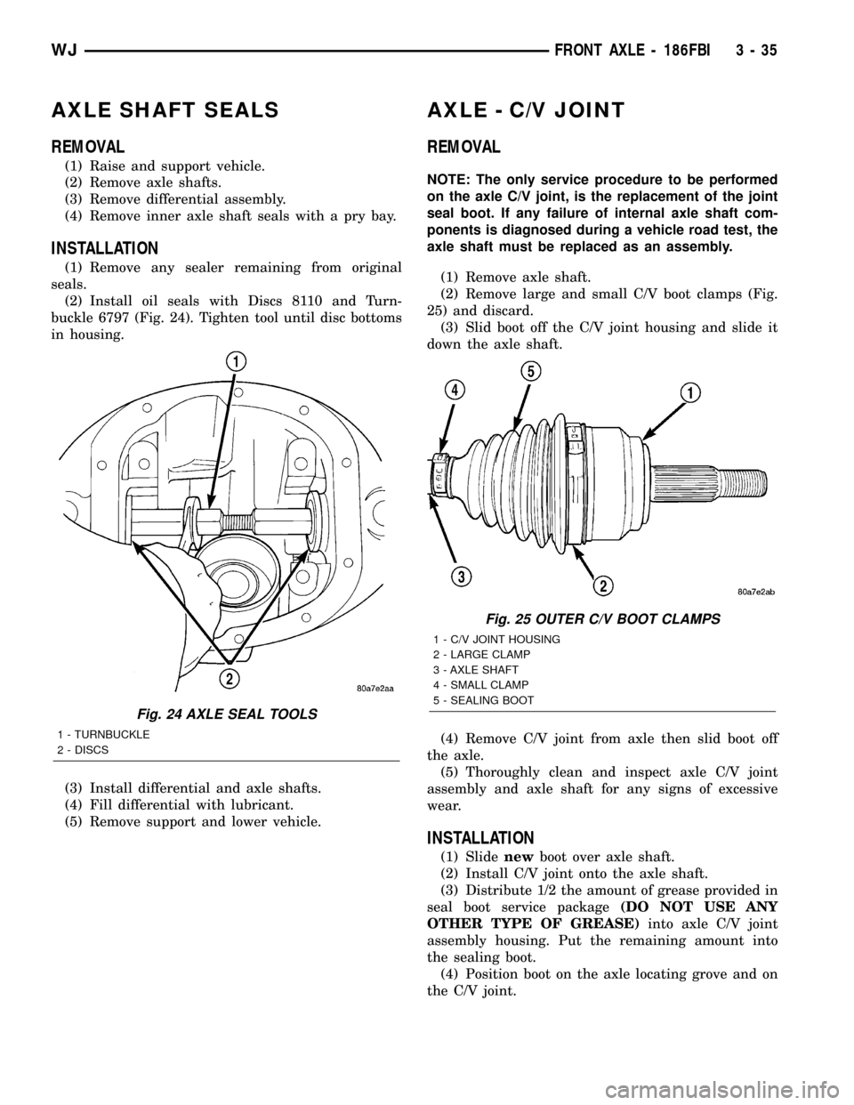
(2) Install oil seals with Discs 8110 and Turn-
buckle 6797 (Fig. 24). Tighten tool until disc bottoms
in housing.
(3) Install differential and axle shafts.
(4) Fill differential with lubricant.
(5) Remove support and lower vehicle.
AXLE - C/V JOINT
REMOVAL
NOTE: The only service procedure to be performed
on the axle C/V joint, is the replacement of the joint
seal boot. If any failure of internal axle shaft com-
ponents is diagnosed during a vehicle road test, the
axle shaft must be replaced as an assembly.
(1) Remove axle shaft.
(2) Remove large and small C/V boot clamps (Fig.
25) and discard.
(3) Slid boot off the C/V joint housing and slide it
down the axle shaft.
(4) Remove C/V joint from axle then slid boot off
the axle.
(5) Thoroughly clean and inspect axle C/V joint
assembly and axle shaft for any signs of excessive
wear.
INSTALLATION
(1) Slidenewboot over axle shaft.
(2) Install C/V joint onto the axle shaft.
(3) Distribute 1/2 the amount of grease provided in
seal boot service package(DO NOT USE ANY
OTHER TYPE OF GREASE)into axle C/V joint
assembly housing. Put the remaining amount into
the sealing boot.
(4) Position boot on the axle locating grove and on
the C/V joint.
Fig. 24 AXLE SEAL TOOLS
1 - TURNBUCKLE
2 - DISCS
Fig. 25 OUTER C/V BOOT CLAMPS
1 - C/V JOINT HOUSING
2 - LARGE CLAMP
3 - AXLE SHAFT
4 - SMALL CLAMP
5 - SEALING BOOT
WJFRONT AXLE - 186FBI 3 - 35
Page 183 of 2199
ADJUSTABLE PEDAL SWITCH
REMOVAL
(1) Remove the steering column opening cover
(Fig. 2)(Refer to 23 - BODY/INSTRUMENT PANEL/
STEERING COLUMN OPENING COVER - REMOV-
AL).
(2) Disconnect the electrical connector from the
adjustable pedal switch.
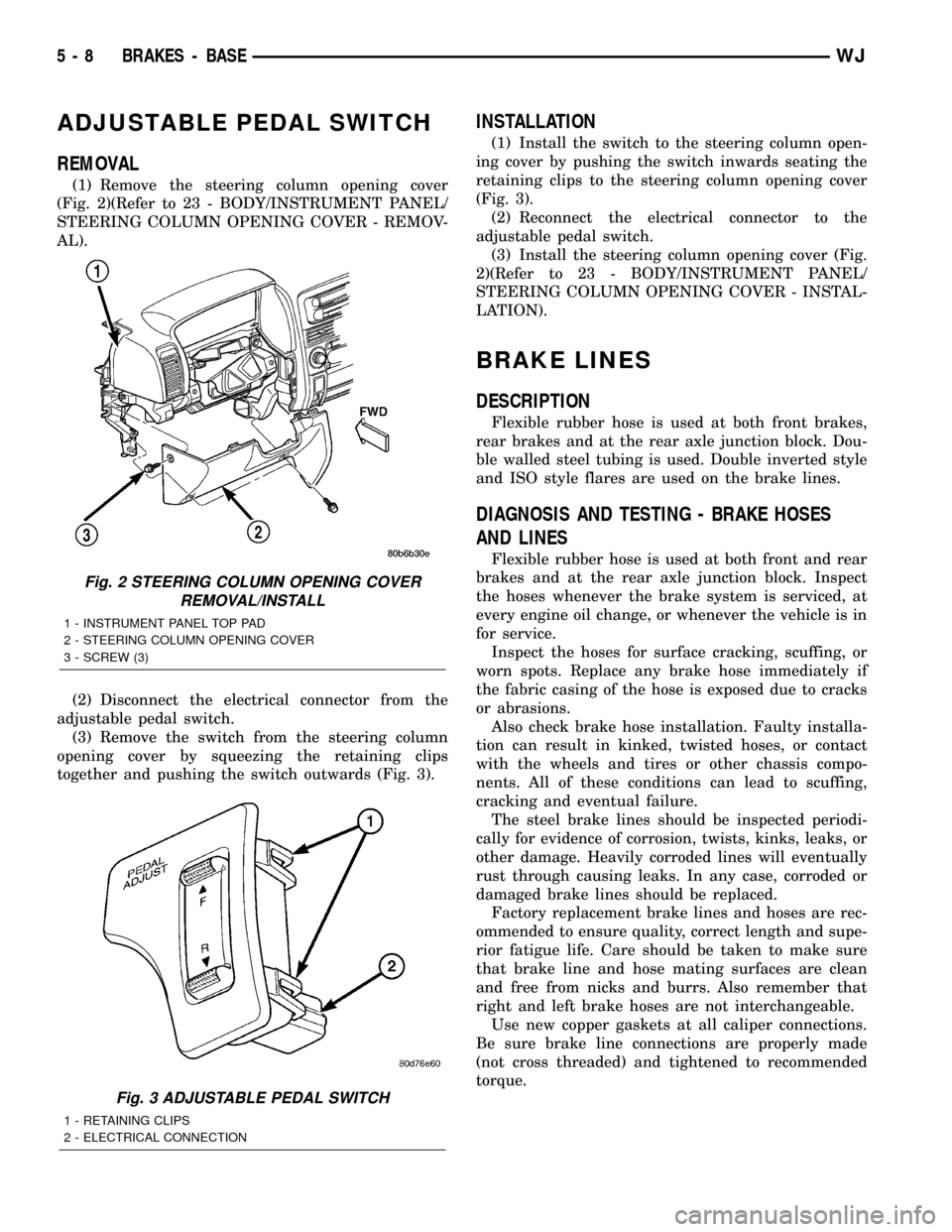
(3) Remove the switch from the steering column
opening cover by squeezing the retaining clips
together and pushing the switch outwards (Fig. 3).
INSTALLATION
(1) Install the switch to the steering column open-
ing cover by pushing the switch inwards seating the
retaining clips to the steering column opening cover
(Fig. 3).
(2) Reconnect the electrical connector to the
adjustable pedal switch.
(3) Install the steering column opening cover (Fig.
2)(Refer to 23 - BODY/INSTRUMENT PANEL/
STEERING COLUMN OPENING COVER - INSTAL-
LATION).
BRAKE LINES
DESCRIPTION
Flexible rubber hose is used at both front brakes,
rear brakes and at the rear axle junction block. Dou-
ble walled steel tubing is used. Double inverted style
and ISO style flares are used on the brake lines.
DIAGNOSIS AND TESTING - BRAKE HOSES
AND LINES
Flexible rubber hose is used at both front and rear
brakes and at the rear axle junction block. Inspect
the hoses whenever the brake system is serviced, at
every engine oil change, or whenever the vehicle is in
for service.
Inspect the hoses for surface cracking, scuffing, or
worn spots. Replace any brake hose immediately if
the fabric casing of the hose is exposed due to cracks
or abrasions.
Also check brake hose installation. Faulty installa-
tion can result in kinked, twisted hoses, or contact
with the wheels and tires or other chassis compo-
nents. All of these conditions can lead to scuffing,
cracking and eventual failure.
The steel brake lines should be inspected periodi-
cally for evidence of corrosion, twists, kinks, leaks, or
other damage. Heavily corroded lines will eventually
rust through causing leaks. In any case, corroded or
damaged brake lines should be replaced.
Factory replacement brake lines and hoses are rec-
ommended to ensure quality, correct length and supe-
rior fatigue life. Care should be taken to make sure
that brake line and hose mating surfaces are clean
and free from nicks and burrs. Also remember that
right and left brake hoses are not interchangeable.
Use new copper gaskets at all caliper connections.
Be sure brake line connections are properly made
(not cross threaded) and tightened to recommended
torque.
Fig. 2 STEERING COLUMN OPENING COVER
REMOVAL/INSTALL
1 - INSTRUMENT PANEL TOP PAD
2 - STEERING COLUMN OPENING COVER
3 - SCREW (3)
Fig. 3 ADJUSTABLE PEDAL SWITCH
1 - RETAINING CLIPS
2 - ELECTRICAL CONNECTION
5 - 8 BRAKES - BASEWJ
Page 198 of 2199
rates into layers, there is mineral oil or other fluid
contamination of the brake fluid.
If brake fluid is contaminated, drain and thor-
oughly flush system. Replace master cylinder with
reservoir, caliper seals, HCU and all hydraulic fluid
hoses.
SPECIFICATIONS
BRAKE FLUID
The brake fluid used in this vehicle must conform
to DOT 3 specifications and SAE J1703 standards.
No other type of brake fluid is recommended or
approved for usage in the vehicle brake system. Use
only Mopar brake fluid or an equivalent from a
tightly sealed container.
CAUTION: Never use reclaimed brake fluid or fluid
from an container which has been left open. An
open container of brake fluid will absorb moisture
from the air and contaminate the fluid.
CAUTION: Never use any type of a petroleum-based
fluid in the brake hydraulic system. Use of such
type fluids will result in seal damage of the vehicle
brake hydraulic system causing a failure of the
vehicle brake system. Petroleum based fluids would
be items such as engine oil, transmission fluid,
power steering fluid, etc.
FLUID RESERVOIR
REMOVAL
(1) Remove reservoir cap and remove fluid with a
cleansuction gun.
(2) Remove the wire connector from the brake fluid
level sensor.
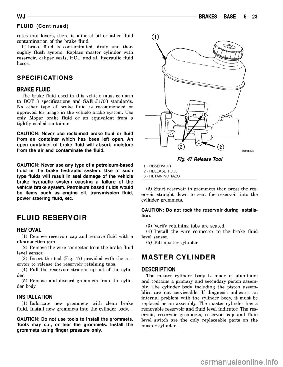
(3) Insert the tool (Fig. 47) provided with the res-
ervoir to release the reservoir retaining tabs.
(4) Pull the reservoir straight up out of the cylin-
der.
(5) Remove and discard grommets from the cylin-
der body.
INSTALLATION
(1) Lubricate new grommets with clean brake
fluid. Install new grommets into the cylinder body.
CAUTION: Do not use tools to install the grommets.
Tools may cut, or tear the grommets. Install the
grommets using finger pressure only.(2) Start reservoir in grommets then press the res-
ervoir straight down to seat the reservoir into the
cylinder grommets.
CAUTION: Do not rock the reservoir during installa-
tion.
(3) Verify retaining tabs are seated.
(4) Install the wire connector to the brake fluid
level sensor.
(5) Fill master cylinder.
MASTER CYLINDER
DESCRIPTION
The master cylinder body is made of aluminum
and contains a primary and secondary piston assem-
bly. The cylinder body including the piston assem-
blies are not serviceable. If diagnosis indicates an
internal problem with the cylinder body, it must be
replaced as an assembly. The master cylinder has a
removable reservoir and fluid level indicator. The res-
ervoir, reservoir grommets, reservoir cap and fluid
level switch are the only replaceable parts on the
master cylinder.
Fig. 47 Release Tool
1 - RESERVOIR
2 - RELEASE TOOL
3 - RETAINING TABS
WJBRAKES - BASE 5 - 23
FLUID (Continued)
Page 235 of 2199
accessory drive belt (Refer to 7 - COOLING/ACCES-
SORY DRIVE/DRIVE BELTS - REMOVAL).
Add coolant to radiator to bring level to within 6.3
mm (1/4 in) of top of thermostat housing.
CAUTION: Avoid overheating. Do not operate
engine for an excessive period of time. Open drain-
cock immediately after test to eliminate boil over.
Start engine and accelerate rapidly three times, to
approximately 3000 rpm while observing coolant. If
internal engine combustion gases are leaking into
cooling system, bubbles will appear in coolant. If bub-
bles do not appear, internal combustion gas leakage
is not present.
DIAGNOSIS AND TESTING - COOLING SYSTEM
DEAERATION
As the engine operates, any air trapped in cooling
system gathers under the radiator cap. The next time
the engine is operated, thermal expansion of coolant
will push any trapped air past radiator cap into the
coolant reserve/overflow tank. Here it escapes to the
atmosphere into the tank. When the engine cools
down the coolant, it will be drawn from the reserve/
overflow tank into the radiator to replace any
removed air.
STANDARD PROCEDURE
STANDARD PROCEDUREÐDRAINING COOLING
SYSTEM 4.7L ENGINE
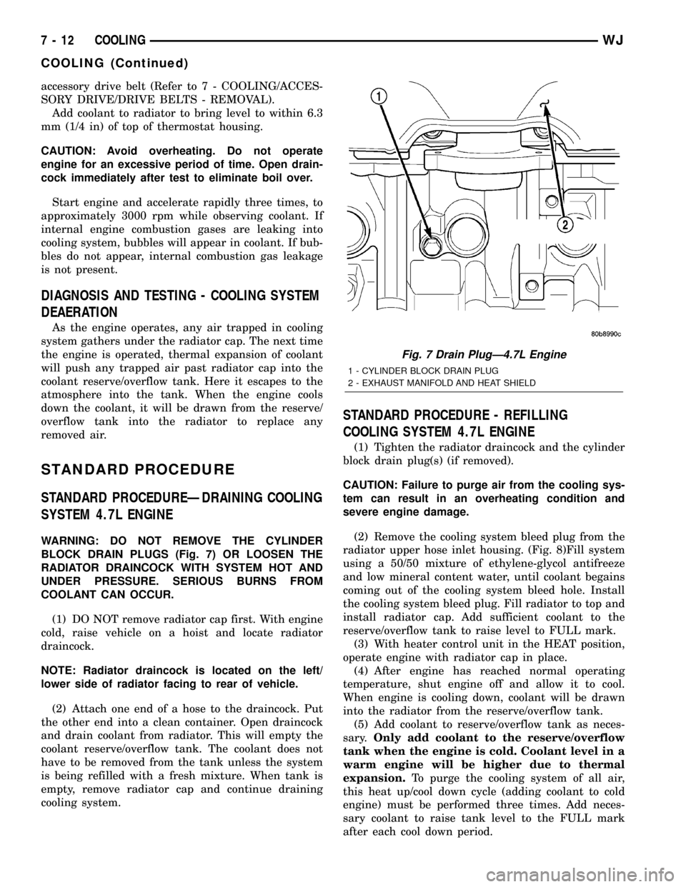
WARNING: DO NOT REMOVE THE CYLINDER
BLOCK DRAIN PLUGS (Fig. 7) OR LOOSEN THE
RADIATOR DRAINCOCK WITH SYSTEM HOT AND
UNDER PRESSURE. SERIOUS BURNS FROM
COOLANT CAN OCCUR.
(1) DO NOT remove radiator cap first. With engine
cold, raise vehicle on a hoist and locate radiator
draincock.
NOTE: Radiator draincock is located on the left/
lower side of radiator facing to rear of vehicle.
(2) Attach one end of a hose to the draincock. Put
the other end into a clean container. Open draincock
and drain coolant from radiator. This will empty the
coolant reserve/overflow tank. The coolant does not
have to be removed from the tank unless the system
is being refilled with a fresh mixture. When tank is
empty, remove radiator cap and continue draining
cooling system.
STANDARD PROCEDURE - REFILLING
COOLING SYSTEM 4.7L ENGINE
(1) Tighten the radiator draincock and the cylinder
block drain plug(s) (if removed).
CAUTION: Failure to purge air from the cooling sys-
tem can result in an overheating condition and
severe engine damage.
(2) Remove the cooling system bleed plug from the
radiator upper hose inlet housing. (Fig. 8)Fill system
using a 50/50 mixture of ethylene-glycol antifreeze
and low mineral content water, until coolant begains
coming out of the cooling system bleed hole. Install
the cooling system bleed plug. Fill radiator to top and
install radiator cap. Add sufficient coolant to the
reserve/overflow tank to raise level to FULL mark.
(3) With heater control unit in the HEAT position,
operate engine with radiator cap in place.
(4) After engine has reached normal operating
temperature, shut engine off and allow it to cool.
When engine is cooling down, coolant will be drawn
into the radiator from the reserve/overflow tank.
(5) Add coolant to reserve/overflow tank as neces-
sary.Only add coolant to the reserve/overflow
tank when the engine is cold. Coolant level in a
warm engine will be higher due to thermal
expansion.To purge the cooling system of all air,
this heat up/cool down cycle (adding coolant to cold
engine) must be performed three times. Add neces-
sary coolant to raise tank level to the FULL mark
after each cool down period.
Fig. 7 Drain PlugÐ4.7L Engine
1 - CYLINDER BLOCK DRAIN PLUG
2 - EXHAUST MANIFOLD AND HEAT SHIELD
7 - 12 COOLINGWJ
COOLING (Continued)
Page 241 of 2199
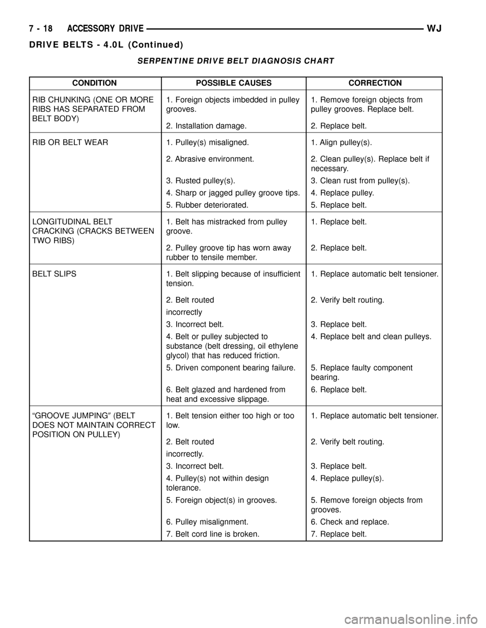
SERPENTINE DRIVE BELT DIAGNOSIS CHART
CONDITION POSSIBLE CAUSES CORRECTION
RIB CHUNKING (ONE OR MORE
RIBS HAS SEPARATED FROM
BELT BODY)1. Foreign objects imbedded in pulley
grooves.1. Remove foreign objects from
pulley grooves. Replace belt.
2. Installation damage. 2. Replace belt.
RIB OR BELT WEAR 1. Pulley(s) misaligned. 1. Align pulley(s).
2. Abrasive environment. 2. Clean pulley(s). Replace belt if
necessary.
3. Rusted pulley(s). 3. Clean rust from pulley(s).
4. Sharp or jagged pulley groove tips. 4. Replace pulley.
5. Rubber deteriorated. 5. Replace belt.
LONGITUDINAL BELT
CRACKING (CRACKS BETWEEN
TWO RIBS)1. Belt has mistracked from pulley
groove.1. Replace belt.
2. Pulley groove tip has worn away
rubber to tensile member.2. Replace belt.
BELT SLIPS 1. Belt slipping because of insufficient
tension.1. Replace automatic belt tensioner.
2. Belt routed 2. Verify belt routing.
incorrectly
3. Incorrect belt. 3. Replace belt.
4. Belt or pulley subjected to
substance (belt dressing, oil ethylene
glycol) that has reduced friction.4. Replace belt and clean pulleys.
5. Driven component bearing failure. 5. Replace faulty component
bearing.
6. Belt glazed and hardened from
heat and excessive slippage.6. Replace belt.
ªGROOVE JUMPING9(BELT
DOES NOT MAINTAIN CORRECT
POSITION ON PULLEY)1. Belt tension either too high or too
low.1. Replace automatic belt tensioner.
2. Belt routed 2. Verify belt routing.
incorrectly.
3. Incorrect belt. 3. Replace belt.
4. Pulley(s) not within design
tolerance.4. Replace pulley(s).
5. Foreign object(s) in grooves. 5. Remove foreign objects from
grooves.
6. Pulley misalignment. 6. Check and replace.
7. Belt cord line is broken. 7. Replace belt.
7 - 18 ACCESSORY DRIVEWJ
DRIVE BELTS - 4.0L (Continued)
Page 242 of 2199
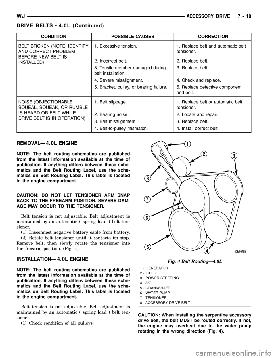
CONDITION POSSIBLE CAUSES CORRECTION
BELT BROKEN (NOTE: IDENTIFY
AND CORRECT PROBLEM
BEFORE NEW BELT IS
INSTALLED)1. Excessive tension. 1. Replace belt and automatic belt
tensioner.
2. Incorrect belt. 2. Replace belt.
3. Tensile member damaged during
belt installation.3. Replace belt.
4. Severe misalignment. 4. Check and replace.
5. Bracket, pulley, or bearing failure. 5. Replace defective component
and belt.
NOISE (OBJECTIONABLE
SQUEAL, SQUEAK, OR RUMBLE
IS HEARD OR FELT WHILE
DRIVE BELT IS IN OPERATION)1. Belt slippage. 1. Replace belt or automatic belt
tensioner.
2. Bearing noise. 2. Locate and repair.
3. Belt misalignment. 3. Replace belt.
4. Belt-to-pulley mismatch. 4. Install correct belt.
REMOVALÐ4.0L ENGINE
NOTE: The belt routing schematics are published
from the latest information available at the time of
publication. If anything differs between these sche-
matics and the Belt Routing Label, use the sche-
matics on Belt Routing Label. This label is located
in the engine compartment.
CAUTION: DO NOT LET TENSIONER ARM SNAP
BACK TO THE FREEARM POSITION, SEVERE DAM-
AGE MAY OCCUR TO THE TENSIONER.
Belt tension is not adjustable. Belt adjustment is
maintained by an automatic ( spring load ) belt ten-
sioner.
(1) Disconnect negative battery cable from battery.
(2) Rotate belt tensioner until it contacts its stop.
Remove belt, then slowly rotate the tensioner into
the freearm position. (Fig. 4).
INSTALLATIONÐ4.0L ENGINE
NOTE: The belt routing schematics are published
from the latest information available at the time of
publication. If anything differs between these sche-
matics and the Belt Routing Label, use the sche-
matics on Belt Routing Label. This label is located
in the engine compartment.
Belt tension is not adjustable. Belt adjustment is
maintained by an automatic ( spring load ) belt ten-
sioner.
(1) Check condition of all pulleys.CAUTION: When installing the serpentine accessory
drive belt, the belt MUST be routed correctly. If not,
the engine may overheat due to the water pump
rotating in the wrong direction (Fig. 4).
Fig. 4 Belt RoutingÐ4.0L
1 - GENERATOR
2 - IDLER
3 - POWER STEERING
4 - A/C
5 - CRANKSHAFT
6 - WATER PUMP
7 - TENSIONER
8 - ACCESSORY DRIVE BELT
WJACCESSORY DRIVE 7 - 19
DRIVE BELTS - 4.0L (Continued)
Page 244 of 2199
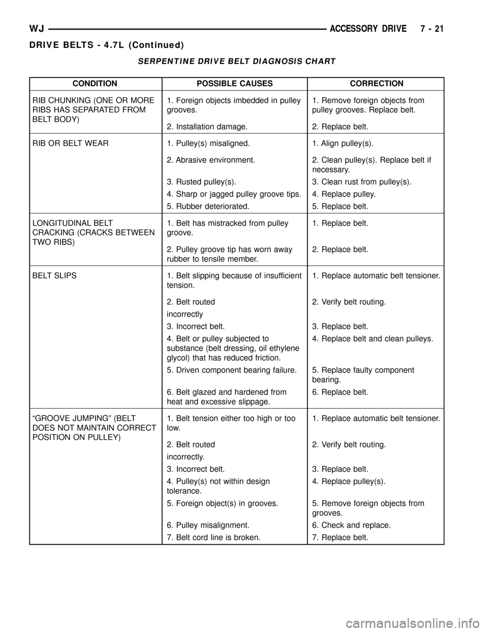
SERPENTINE DRIVE BELT DIAGNOSIS CHART
CONDITION POSSIBLE CAUSES CORRECTION
RIB CHUNKING (ONE OR MORE
RIBS HAS SEPARATED FROM
BELT BODY)1. Foreign objects imbedded in pulley
grooves.1. Remove foreign objects from
pulley grooves. Replace belt.
2. Installation damage. 2. Replace belt.
RIB OR BELT WEAR 1. Pulley(s) misaligned. 1. Align pulley(s).
2. Abrasive environment. 2. Clean pulley(s). Replace belt if
necessary.
3. Rusted pulley(s). 3. Clean rust from pulley(s).
4. Sharp or jagged pulley groove tips. 4. Replace pulley.
5. Rubber deteriorated. 5. Replace belt.
LONGITUDINAL BELT
CRACKING (CRACKS BETWEEN
TWO RIBS)1. Belt has mistracked from pulley
groove.1. Replace belt.
2. Pulley groove tip has worn away
rubber to tensile member.2. Replace belt.
BELT SLIPS 1. Belt slipping because of insufficient
tension.1. Replace automatic belt tensioner.
2. Belt routed 2. Verify belt routing.
incorrectly
3. Incorrect belt. 3. Replace belt.
4. Belt or pulley subjected to
substance (belt dressing, oil ethylene
glycol) that has reduced friction.4. Replace belt and clean pulleys.
5. Driven component bearing failure. 5. Replace faulty component
bearing.
6. Belt glazed and hardened from
heat and excessive slippage.6. Replace belt.
ªGROOVE JUMPING9(BELT
DOES NOT MAINTAIN CORRECT
POSITION ON PULLEY)1. Belt tension either too high or too
low.1. Replace automatic belt tensioner.
2. Belt routed 2. Verify belt routing.
incorrectly.
3. Incorrect belt. 3. Replace belt.
4. Pulley(s) not within design
tolerance.4. Replace pulley(s).
5. Foreign object(s) in grooves. 5. Remove foreign objects from
grooves.
6. Pulley misalignment. 6. Check and replace.
7. Belt cord line is broken. 7. Replace belt.
WJACCESSORY DRIVE 7 - 21
DRIVE BELTS - 4.7L (Continued)
Page 245 of 2199
CONDITION POSSIBLE CAUSES CORRECTION
BELT BROKEN (NOTE: IDENTIFY
AND CORRECT PROBLEM
BEFORE NEW BELT IS
INSTALLED)1. Excessive tension. 1. Replace belt and automatic belt
tensioner.
2. Incorrect belt. 2. Replace belt.
3. Tensile member damaged during
belt installation.3. Replace belt.
4. Severe misalignment. 4. Check and replace.
5. Bracket, pulley, or bearing failure. 5. Replace defective component
and belt.
NOISE (OBJECTIONABLE
SQUEAL, SQUEAK, OR RUMBLE
IS HEARD OR FELT WHILE
DRIVE BELT IS IN OPERATION)1. Belt slippage. 1. Replace belt or automatic belt
tensioner.
2. Bearing noise. 2. Locate and repair.
3. Belt misalignment. 3. Replace belt.
4. Belt-to-pulley mismatch. 4. Install correct belt.
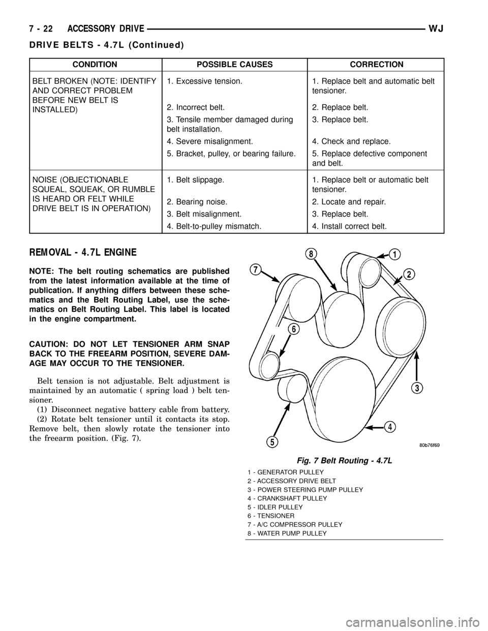
REMOVAL - 4.7L ENGINE
NOTE: The belt routing schematics are published
from the latest information available at the time of
publication. If anything differs between these sche-
matics and the Belt Routing Label, use the sche-
matics on Belt Routing Label. This label is located
in the engine compartment.
CAUTION: DO NOT LET TENSIONER ARM SNAP
BACK TO THE FREEARM POSITION, SEVERE DAM-
AGE MAY OCCUR TO THE TENSIONER.
Belt tension is not adjustable. Belt adjustment is
maintained by an automatic ( spring load ) belt ten-
sioner.
(1) Disconnect negative battery cable from battery.
(2) Rotate belt tensioner until it contacts its stop.
Remove belt, then slowly rotate the tensioner into
the freearm position. (Fig. 7).
Fig. 7 Belt Routing - 4.7L
1 - GENERATOR PULLEY
2 - ACCESSORY DRIVE BELT
3 - POWER STEERING PUMP PULLEY
4 - CRANKSHAFT PULLEY
5 - IDLER PULLEY
6 - TENSIONER
7 - A/C COMPRESSOR PULLEY
8 - WATER PUMP PULLEY
7 - 22 ACCESSORY DRIVEWJ
DRIVE BELTS - 4.7L (Continued)
Page 249 of 2199
The use of aluminum cylinder blocks, cylinder
heads, and water pumps requires special corrosion
protection. MopartAntifreeze/Coolant, 5
Year/100,000 Mile Formula (MS-9769), or the equiva-
lent ethylene glycol base coolant with organic corro-
sion inhibitors (called HOAT, for Hybrid Organic
Additive Technology) is recommended. This coolant
offers the best engine cooling without corrosion when
mixed with 50% Ethylene Glycol and 50% distilled
water to obtain a freeze point of -37ÉC (-35ÉF). If it
loses color or becomes contaminated, drain, flush,
and replace with fresh properly mixed coolant solu-
tion.
CAUTION: MoparTAntifreeze/Coolant, 5
Year/100,000 Mile Formula (MS-9769) may not be
mixed with any other type of antifreeze. Mixing of
coolants other than specified (non-HOAT or other
HOAT), may result in engine damage that may not
be covered under the new vehicle warranty, and
decreased corrosion protection.
COOLANT PERFORMANCE
The required ethylene-glycol (antifreeze) and water
mixture depends upon climate and vehicle operating
conditions. The coolant performance of various mix-
tures follows:
Pure Water-Water can absorb more heat than a
mixture of water and ethylene-glycol. This is for pur-
pose of heat transfer only. Water also freezes at a
higher temperature and allows corrosion.
100 percent Ethylene-Glycol-The corrosion
inhibiting additives in ethylene-glycol need the pres-
ence of water to dissolve. Without water, additives
form deposits in system. These act as insulation
causing temperature to rise to as high as 149ÉC
(300ÉF). This temperature is hot enough to melt plas-
tic and soften solder. The increased temperature can
result in engine detonation. In addition, 100 percent
ethylene-glycol freezes at -22ÉC (-8ÉF).
50/50 Ethylene-Glycol and Water-Is the recom-
mended mixture, it provides protection against freez-
ing to -37ÉC (-34ÉF). The antifreeze concentration
must alwaysbe a minimum of 44 percent, year-
round in all climates. If percentage is lower, engine
parts may be eroded by cavitation. Maximum protec-
tion against freezing is provided with a 68 percent
antifreeze concentration, which prevents freezing
down to -67.7ÉC (-90ÉF). A higher percentage will
freeze at a warmer temperature. Also, a higher per-
centage of antifreeze can cause the engine to over-
heat because specific heat of antifreeze is lower than
that of water.CAUTION: Richer antifreeze mixtures cannot be
measured with normal field equipment and can
cause problems associated with 100 percent ethyl-
ene-glycol.
COOLANT SELECTION AND ADDITIVES
The use of aluminum cylinder blocks, cylinder
heads and water pumps requires special corrosion
protection. Only MopartAntifreeze/Coolant, 5
Year/100,000 Mile Formula (glycol base coolant with
corrosion inhibitors called HOAT, for Hybrid Organic
Additive Technology) is recommended. This coolant
offers the best engine cooling without corrosion when
mixed with 50% distilled water to obtain to obtain a
freeze point of -37ÉC (-35ÉF). If it loses color or
becomes contaminated, drain, flush, and replace with
fresh properly mixed coolant solution.
CAUTION: Do not use coolant additives that are
claimed to improve engine cooling.
OPERATION
Coolant flows through the engine block absorbing
the heat from the engine, then flows to the radiator
where the cooling fins in the radiator transfers the
heat from the coolant to the atmosphere. During cold
weather the ethylene-glycol coolant prevents water
present in the cooling system from freezing within
temperatures indicated by mixture ratio of coolant to
water.
COOLANT LEVEL SENSOR
REMOVAL
(1) Open Hood.
(2) Disconnect electrical connector from coolant
level sensor.
(3) Pull coolant level sensor out of coolant recovery
pressure container.
INSTALLATION
NOTE: Make sure the coolant level sensor fully
seats into the rubber grommet. Failure to do so
may cause inaccurate coolant level readings and
leaks.
7 - 26 ENGINEWJ
COOLANT (Continued)