Front bumper JEEP GRAND CHEROKEE 2003 WJ / 2.G Workshop Manual
[x] Cancel search | Manufacturer: JEEP, Model Year: 2003, Model line: GRAND CHEROKEE, Model: JEEP GRAND CHEROKEE 2003 WJ / 2.GPages: 2199, PDF Size: 76.01 MB
Page 20 of 2199

²Do not allow towing equipment to contact the
disabled vehicle's fuel tank.
²Do not allow anyone under the disabled vehicle
while it is lifted by the towing device.
²Do not allow passengers to ride in a vehicle
being towed.
²Always observe state and local laws regarding
towing regulations.
²Do not tow a vehicle in a manner that could
jeopardize the safety of the operator, pedestrians or
other motorists.
²Do not attach tow chains, T-hooks, or J-hooks to
a bumper, steering linkage, drive shafts or a non-re-
inforced frame hole.
²Do not tow a heavily loaded vehicle. Use a flat-
bed device to transport a loaded vehicle.
TWO-WHEEL-DRIVE VEHICLE TOWING
DaimlerChrysler Corporation recommends that a
vehicle be towed with the rear end lifted, whenever
possible.
WARNING: WHEN TOWING A DISABLED VEHICLE
AND THE DRIVE WHEELS ARE SECURED IN A
WHEEL LIFT OR TOW DOLLIES, ENSURE THE
TRANSMISSION IS IN THE PARK POSITION (AUTO-
MATIC TRANSMISSION) OR A FORWARD DRIVE
GEAR (MANUAL TRANSMISSION).
WARNING: ENSURE VEHICLE IS ON A LEVEL SUR-
FACE OR THE WHEELS ARE BLOCKED TO PRE-
VENT VEHICLE FROM ROLLING.
TWO WHEEL DRIVE TOWING-REAR END LIFTED
CAUTION: Do not use steering column lock to
secure steering wheel during towing operation.
2WD vehicles can be towed with the front wheels
on the surface for extended distances at speeds not
exceeding 48 km/h (30 mph).
(1) Attach wheel lift device to rear wheels.
(2) Place the transmission in neutral.
(3) Raise vehicle to towing position.
(4) Attach safety chains. Route chains so not to
interfere with tail pipe when vehicle is lifted.
(5) Turn the ignition switch to the OFF position to
unlock the steering wheel.
CAUTION: Do not use steering column lock to
secure steering wheel during towing operation.
(6) Secure steering wheel in straight ahead posi-
tion with a clamp device designed for towing.
(7) Place transmission in park.
TWO WHEEL DRIVE TOWING-FRONT END LIFTED
CAUTION: Many vehicles are equipped with air
dams, spoilers, and/or ground effect panels. To
avoid component damage, a wheel-lift towing vehi-
cle or a flat-bed hauling vehicle is recommended.
(1) Attach wheel lift device to rear wheels.
(2) Place the transmission in neutral.
(3) Raise the rear of the vehicle off the ground and
install tow dollies under rear wheels.
(4) Attach wheel lift device to front wheels and
raise vehicle to towing position.
(5) Attach the safety chains.
CAUTION: Do not use steering column lock to
secure steering wheel during towing operation.
(6) Turn the ignition switch to the OFF position to
unlock the steering wheel.
(7) Secure steering wheel in straight ahead posi-
tion with a clamp device designed for towing.
(8) Place transmission in park.
FOUR-WHEEL-DRIVE VEHICLE TOWING
DaimlerChrysler Corporation recommends that a
4WD vehicle be transported on a flat-bed device. A
Wheel-lift device can be used providedthe trailing
wheels are off the ground and positioned in
tow dollies.
WARNING: WHEN TOWING A DISABLED VEHICLE
AND THE DRIVE WHEELS ARE SECURED IN A
WHEEL LIFT OR TOW DOLLIES, ENSURE THE
TRANSMISSION IS IN THE PARK POSITION.
CAUTION: Many vehicles are equipped with air
dams, spoilers, and/or ground effect panels. To
avoid component damage, a wheel-lift towing vehi-
cle or a flat-bed hauling vehicle is recommended.
FOUR WHEEL DRIVE TOWINGÐREAR END LIFTED
WARNING: ENSURE VEHICLE IS ON A LEVEL SUR-
FACE OR THE WHEELS ARE BLOCKED TO PRE-
VENT VEHICLE FROM ROLLING.
(1) Attach wheel lift device to front wheels.
(2) Place the transmission in neutral.
(3) Raise the front of the vehicle off the ground
and install tow dollies under front wheels.
(4) Attach wheel lift device to rear wheels and
raise vehicle to towing position.
(5) Attach safety chains. Route chains so not to
interfere with tail pipe when vehicle is lifted.
WJLUBRICATION & MAINTENANCE 0 - 9
TOWING (Continued)
Page 24 of 2199

WHEEL ALIGNMENT
TABLE OF CONTENTS
page page
WHEEL ALIGNMENT
DESCRIPTION..........................3
OPERATION............................3
STANDARD PROCEDURE
STANDARD PROCEDURE - CAMBER.......3STANDARD PROCEDURE - CASTER.......4
STANDARD PROCEDURE - TOE POSITION . . 4
SPECIFICATIONS
ALIGNMENT..........................5
WHEEL ALIGNMENT
DESCRIPTION
Wheel alignment involves the correct positioning of
the wheels in relation to the vehicle. The positioning
is accomplished through suspension and steering
linkage adjustments. An alignment is considered
essential for efficient steering, good directional stabil-
ity and to minimize tire wear. The most important
measurements of an alignment are caster, camber
and toe position (Fig. 1).
CAUTION: Never attempt to modify suspension or
steering components by heating or bending.
CAUTION: Components attached with a nut and cot-
ter pin must be torqued to specification. Then if the
slot in the nut does not line up with the cotter pin
hole, tighten nut until it is aligned. Never loosen the
nut to align the cotter pin hole.
NOTE: Periodic lubrication of the front suspension/
steering system components may be required. Rub-
ber bushings must never be lubricated, Refer to
Lubrication And Maintenance for the recommended
maintenance schedule.
OPERATION
²CASTERis the forward or rearward tilt of the
steering knuckle from vertical. Tilting the top of the
knuckle rearward provides positive caster. Tilting the
top of the knuckle forward provides negative caster.
Caster is a directional stability angle. This angle
enables the front wheels to return to a straight
ahead position after turns (Fig. 1).
²CAMBERis the inward or outward tilt of the
wheel relative to the center of the vehicle. Tilting the
top of the wheel inward provides negative camber.
Tilting the top of the wheel outward provides positive
camber. Incorrect camber will cause wear on theinside or outside edge of the tire. The angle is not
adjustable, damaged component(s) must be replaced
to correct the camber angle (Fig. 1).
²WHEEL TOE POSITIONis the difference
between the leading inside edges and trailing inside
edges of the front tires. Incorrect wheel toe position
is the most common cause of unstable steering and
uneven tire wear. The wheel toe position is thefinal
front wheel alignment adjustment (Fig. 1).
²STEERING AXIS INCLINATION ANGLEis
measured in degrees and is the angle that the steer-
ing knuckles are tilted. The inclination angle has a
fixed relationship with the camber angle. It will not
change except when a spindle or ball stud is dam-
aged or bent. The angle is not adjustable, damaged
component(s) must be replaced to correct the steering
axis inclination angle.
²THRUST ANGLEis the angle of the rear axle
relative to the centerline of the vehicle. Incorrect
thrust angle can cause off-center steering and exces-
sive tire wear. This angle is not adjustable, damaged
component(s) must be replaced to correct the thrust
angle (Fig. 1).
STANDARD PROCEDURE
STANDARD PROCEDURE - CAMBER
Before each alignment reading the vehicle should
be jounced (rear first, then front). Grasp each
bumper at the center and jounce the vehicle up and
down three times. Always release the bumper in the
down position.
To obtain an accurate alignment, a 4 wheel align-
ment machine must be used and the equipment cali-
bration verified.
The wheel camber angle is preset. This angle is not
adjustable and cannot be altered.
WJWHEEL ALIGNMENT 2 - 3
Page 25 of 2199

STANDARD PROCEDURE - CASTER
Before each alignment reading the vehicle should
be jounced (rear first, then front). Grasp each
bumper at the center and jounce the vehicle up and
down three times. Always release the bumper in the
down position.
To obtain an accurate alignment, a 4 wheel align-
ment machine must be used and the equipment cali-
bration verified.
The wheel caster angle is preset. This angle is not
adjustable and cannot be altered.
STANDARD PROCEDURE - TOE POSITION
Before each alignment reading the vehicle should
be jounced (rear first, then front). Grasp each
bumper at the center and jounce the vehicle up and
down three times. Always release the bumper in the
down position.To obtain an accurate alignment, a 4 wheel align-
ment machine must be used and the equipment cali-
bration verified.
NOTE: For an accurate wheel toe position adjust-
ment the engine must be engine running.
(1) Apply parking brakes.
(2) Start the engine and turn wheels both ways
before straightening the steering wheel. Center and
secure the steering wheel.
(3) Loosen the tie rod adjustment sleeve clamp
bolts (Fig. 2).
(4) Turn the sleeve to obtain the preferred positive
TOE-IN specification. Position the clamp bolts as
shown (Fig. 2) for proper clearance.
(5) Tighten the clamp bolts to 68 N´m (50 ft. lbs.).
Fig. 1 Wheel Alignment Measurements
1 - WHEEL CENTERLINE
2 - NEGATIVE CAMBER ANGLE
3 - PIVOT CENTERLINE
4 - SCRUB RADIUS
5 - TRUE VERTICAL6 - KING PIN
7 - VERTICAL
8 - POSITIVE CASTER
2 - 4 WHEEL ALIGNMENTWJ
WHEEL ALIGNMENT (Continued)
Page 27 of 2199

FRONT
TABLE OF CONTENTS
page page
FRONT
DESCRIPTION..........................6
STANDARD PROCEDURE - SERVICE
WARNINGS AND CAUTIONS..............6
SPECIFICATIONS
TORQUE CHART......................7
SPECIAL TOOLS
FRONT SUSPENSION...................8
BUSHINGS
REMOVAL.............................9
INSTALLATION..........................9
HUB / BEARING
DESCRIPTION..........................9
OPERATION............................9
REMOVAL.............................9
INSTALLATION.........................10
KNUCKLE
DESCRIPTION.........................10
OPERATION...........................10
REMOVAL - STEERING KNUCKLE..........10
INSTALLATION.........................10
LOWER BALL JOINT
REMOVAL.............................11
LOWER CONTROL ARM
DESCRIPTION.........................11
OPERATION...........................11
REMOVAL.............................11
INSTALLATION.........................11SHOCK
DESCRIPTION.........................12
OPERATION...........................12
REMOVAL.............................12
INSTALLATION.........................12
SPRING
DESCRIPTION.........................12
OPERATION...........................13
REMOVAL.............................13
INSTALLATION.........................13
STABILIZER BAR
DESCRIPTION.........................14
OPERATION...........................14
REMOVAL.............................14
INSTALLATION.........................14
TRACK BAR
DESCRIPTION.........................14
OPERATION...........................14
REMOVAL.............................14
INSTALLATION.........................14
UPPER BALL JOINT
REMOVAL.............................15
UPPER CONTROL ARM
DESCRIPTION.........................16
OPERATION...........................16
REMOVAL.............................16
INSTALLATION.........................16
FRONT
DESCRIPTION
The front suspension (Fig. 1) is a link/coil design
comprised of :
²Drive axle
²Shock absorbers
²Coil springs
²Upper and lower suspension arms
²Stabilizer bar
²Track bar
²Jounce bumpers
CAUTION: Components attached with a nut and cot-
ter pin must be torqued to specification. Then if the
slot in the nut does not line up with the cotter pin
hole, tighten nut until it is aligned. Never loosen the
nut to align the cotter pin hole.CAUTION: Suspension components with rubber
bushings must be tightened with the vehicle at nor-
mal ride height. It is important to have the springs
supporting the weight of the vehicle when the fas-
teners are torqued. If springs are not at their normal
ride position, vehicle ride comfort will be affected
and cause premature bushing wear.
STANDARD PROCEDURE - SERVICE
WARNINGS AND CAUTIONS
CAUTION: Suspension components with rubber
bushings must be tightened with the vehicle at nor-
mal ride height. It is important to have the springs
supporting the weight of the vehicle when the fas-
teners are torqued. If springs are not at their normal
ride position, vehicle ride comfort will be affected
and cause premature bushing wear.
2 - 6 FRONTWJ
Page 264 of 2199
(6) Start the engine and operate at 2400 rpm.
Within ten minutes the air temperature (indicated on
the dial thermometer) should be up to 93É C (200É F).
Fan driveengagementshould have started to occur
at between 91É to 96É C (195É to 205É F). Engage-
ment is distinguishable by a definiteincreasein fan
flow noise (roaring). The timing light also will indi-
cate an increase in the speed of the fan.
(7) When the air temperature reaches 93É C (200É
F), remove the plastic sheet. Fan drivedisengage-
mentshould have started to occur at between 62É to
85É C (145É to 185É F). A definitedecreaseof fan
flow noise (roaring) should be noticed. If not, replace
the defective viscous fan drive unit.
PWM FAN CONTROL MODULE -
4.0L
DESCRIPTION
The pulse width modulated (PWM) radiator cooling
fan relay is located behind the front bumper fascia
below the right headlamp.
OPERATION
The PWM relay is used to control the speed of the
electric radiator cooling fan. It allows for multiple fan
speeds. This allows for improved fan noise and A/C
performance, better engine cooling, and additional
vehicle power.
PWM relay operation is controlled by the Power-
train Control Module (PCM). To operate the PWM
relay, the PCM looks at inputs from:
²Engine coolant temperature
²Ambient temperature from the body controller
²Vehicle speed
²Transmission oil temperature
²A/C switch position (A/C request)
REMOVAL
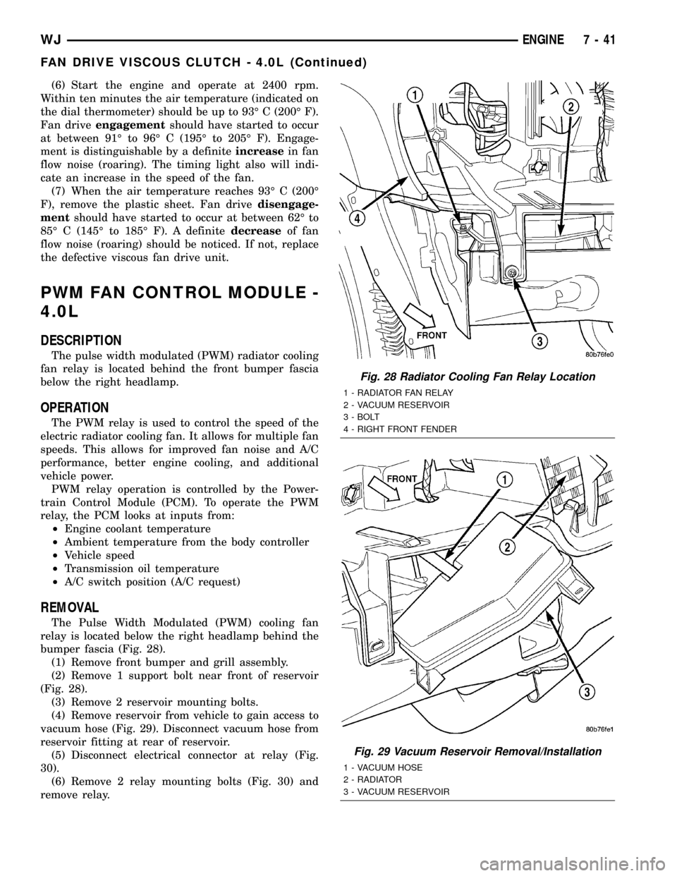
The Pulse Width Modulated (PWM) cooling fan
relay is located below the right headlamp behind the
bumper fascia (Fig. 28).
(1) Remove front bumper and grill assembly.
(2) Remove 1 support bolt near front of reservoir
(Fig. 28).
(3) Remove 2 reservoir mounting bolts.
(4) Remove reservoir from vehicle to gain access to
vacuum hose (Fig. 29). Disconnect vacuum hose from
reservoir fitting at rear of reservoir.
(5) Disconnect electrical connector at relay (Fig.
30).
(6) Remove 2 relay mounting bolts (Fig. 30) and
remove relay.
Fig. 28 Radiator Cooling Fan Relay Location
1 - RADIATOR FAN RELAY
2 - VACUUM RESERVOIR
3 - BOLT
4 - RIGHT FRONT FENDER
Fig. 29 Vacuum Reservoir Removal/Installation
1 - VACUUM HOSE
2 - RADIATOR
3 - VACUUM RESERVOIR
WJENGINE 7 - 41
FAN DRIVE VISCOUS CLUTCH - 4.0L (Continued)
Page 265 of 2199
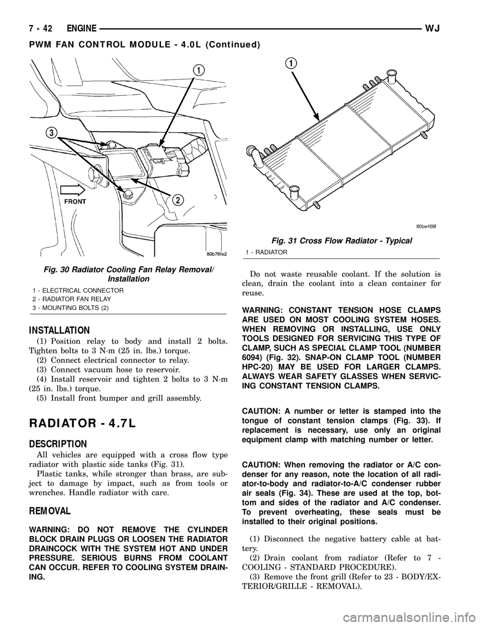
INSTALLATION
(1) Position relay to body and install 2 bolts.
Tighten bolts to 3 N´m (25 in. lbs.) torque.
(2) Connect electrical connector to relay.
(3) Connect vacuum hose to reservoir.
(4) Install reservoir and tighten 2 bolts to 3 N´m
(25 in. lbs.) torque.
(5) Install front bumper and grill assembly.
RADIATOR - 4.7L
DESCRIPTION
All vehicles are equipped with a cross flow type
radiator with plastic side tanks (Fig. 31).
Plastic tanks, while stronger than brass, are sub-
ject to damage by impact, such as from tools or
wrenches. Handle radiator with care.
REMOVAL
WARNING: DO NOT REMOVE THE CYLINDER
BLOCK DRAIN PLUGS OR LOOSEN THE RADIATOR
DRAINCOCK WITH THE SYSTEM HOT AND UNDER
PRESSURE. SERIOUS BURNS FROM COOLANT
CAN OCCUR. REFER TO COOLING SYSTEM DRAIN-
ING.Do not waste reusable coolant. If the solution is
clean, drain the coolant into a clean container for
reuse.
WARNING: CONSTANT TENSION HOSE CLAMPS
ARE USED ON MOST COOLING SYSTEM HOSES.
WHEN REMOVING OR INSTALLING, USE ONLY
TOOLS DESIGNED FOR SERVICING THIS TYPE OF
CLAMP, SUCH AS SPECIAL CLAMP TOOL (NUMBER
6094) (Fig. 32). SNAP-ON CLAMP TOOL (NUMBER
HPC-20) MAY BE USED FOR LARGER CLAMPS.
ALWAYS WEAR SAFETY GLASSES WHEN SERVIC-
ING CONSTANT TENSION CLAMPS.
CAUTION: A number or letter is stamped into the
tongue of constant tension clamps (Fig. 33). If
replacement is necessary, use only an original
equipment clamp with matching number or letter.
CAUTION: When removing the radiator or A/C con-
denser for any reason, note the location of all radi-
ator-to-body and radiator-to-A/C condenser rubber
air seals (Fig. 34). These are used at the top, bot-
tom and sides of the radiator and A/C condenser.
To prevent overheating, these seals must be
installed to their original positions.
(1) Disconnect the negative battery cable at bat-
tery.
(2) Drain coolant from radiator (Refer to 7 -
COOLING - STANDARD PROCEDURE).
(3) Remove the front grill (Refer to 23 - BODY/EX-
TERIOR/GRILLE - REMOVAL).
Fig. 30 Radiator Cooling Fan Relay Removal/
Installation
1 - ELECTRICAL CONNECTOR
2 - RADIATOR FAN RELAY
3 - MOUNTING BOLTS (2)
Fig. 31 Cross Flow Radiator - Typical
1 - RADIATOR
7 - 42 ENGINEWJ
PWM FAN CONTROL MODULE - 4.0L (Continued)
Page 468 of 2199

(from rear of vehicle forward) to verify accuracy of
the line placement.
(4) Rock vehicle side-to-side three times to allow
suspension to stabilize.
(5) Jounce front suspension three times by pushing
downward on front bumper and releasing.
(6) Measure the distance from the center of head-
lamp lens to the floor. Transfer measurement to the
alignment screen (with tape). Use this line for
up/down adjustment reference.
(7) Measure distance from the centerline of the
vehicle to the center of each headlamp being aligned.
Transfer measurements to screen (with tape) to each
side of vehicle centerline. Use these lines for left/
right adjustment reference.
HEADLAMP ADJUSTMENT
A properly aimed low beam will project the top
edge of the beam intensity pattern on the screen
from 25 mm (1 in.) above to 75 mm (3 in.) below
headlamp centerline. The side-to-side left edge of the
beam intensity pattern should be from 50 mm (2 in.)
left to 50 mm (2 in.) right of headlamp centerline
(Fig. 17).
(1) Clean front of the headlamps.
(2) Place headlamps on LOW beam.(3) Cover front of the headlamp that is not being
adjusted.
(4) Turn adjustment screw (Fig. 18) and (Fig. 19)
until the top edge of the beam intensity pattern is
positioned within 25 mm (1 in.) above or 75 mm (3
in.) below the headlamp horizontal centerline.
(5) Cover front of the headlamp and adjust the
other headlamp beam as instructed below.
(6) Rotate the adjustment screw until the top edge
of the beam intensity pattern is positioned within 25
mm (1 in.) above or 75 mm (3 in.) below the head-
lamp horizontal centerline.
LICENSE PLATE LAMP
REMOVAL
REMOVAL - BULB
(1) Remove lamp assembly from liftgate lamp mod-
ule.
(2) Rotate bulb socket counterclockwise to discon-
nect bulb socket from lamp.
(3) Remove bulb from socket.
Fig. 16 Headlamp Alignment ScreenÐTypical
1 - CENTER OF VEHICLE TO CENTER OF HEADLAMP LENS
2 - FLOOR TO CENTER OF HEADLAMP LENS
3 - 7.62 METERS (25 FEET)4 - FRONT OF HEADLAMP
5 - VEHICLE CENTERLINE
WJLAMPS/LIGHTING - EXTERIOR 8L - 17
HEADLAMP UNIT (Continued)
Page 589 of 2199
(4) Install airbag module. Refer to Group 8M, Pas-
sive Restraint Systems.
(5) Connect negative battery cable.
VACUUM RESERVOIR
DESCRIPTION
The vacuum reservoir is a plastic storage tank con-
nected to an engine vacuum source by vacuum lines.
OPERATION
The vacuum reservoir is used to supply the vac-
uum needed to maintain proper speed control opera-
tion when engine vacuum drops, such as in climbing
a grade while driving. A one-way check valve is used
in the vacuum line between the reservoir and the
vacuum source. This check valve is used to trap
engine vacuum in the reservoir. On certain vehicle
applications, this reservoir is shared with the heat-
ing/air-conditioning system. The vacuum reservoir
cannot be repaired and must be replaced if faulty.
DIAGNOSIS AND TESTING - VACUUM
RESERVOIR
(1) Disconnect vacuum hose at speed control servo
and install a vacuum gauge into the disconnected
hose.
(2) Start engine and observe gauge at idle. Vac-
uum gauge should read at least ten inches of mer-
cury.
(3) If vacuum is less than ten inches of mercury,
determine source of leak. Check vacuum line to
engine for leaks. Also check actual engine intake
manifold vacuum. If manifold vacuum does not meet
this requirement, check for poor engine performance
and repair as necessary.
(4) If vacuum line to engine is not leaking, check
for leak at vacuum reservoir. To locate and gain
access to reservoir, refer to Vacuum Reservoir Remov-
al/Installation in this group. Disconnect vacuum line
at reservoir and connect a hand-operated vacuum
pump to reservoir fitting. Apply vacuum. Reservoir
vacuum should not bleed off. If vacuum is being lost,
replace reservoir.
(5) Verify operation of one-way check valve and
check it for leaks.
(a) Locate one-way check valve. The valve is
located in vacuum line between vacuum reservoir
and engine vacuum source. Disconnect vacuum
hoses (lines) at each end of valve.
(b) Connect a hand-operated vacuum pump to
reservoir end of check valve. Apply vacuum. Vac-
uum should not bleed off. If vacuum is being lost,
replace one-way check valve.
(c) Connect a hand-operated vacuum pump to
vacuum source end of check valve. Apply vacuum.
Vacuum should flow through valve. If vacuum is
not flowing, replace one-way check valve. Seal the
fitting at opposite end of valve with a finger and
apply vacuum. If vacuum will not hold, diaphragm
within check valve has ruptured. Replace valve.
REMOVAL
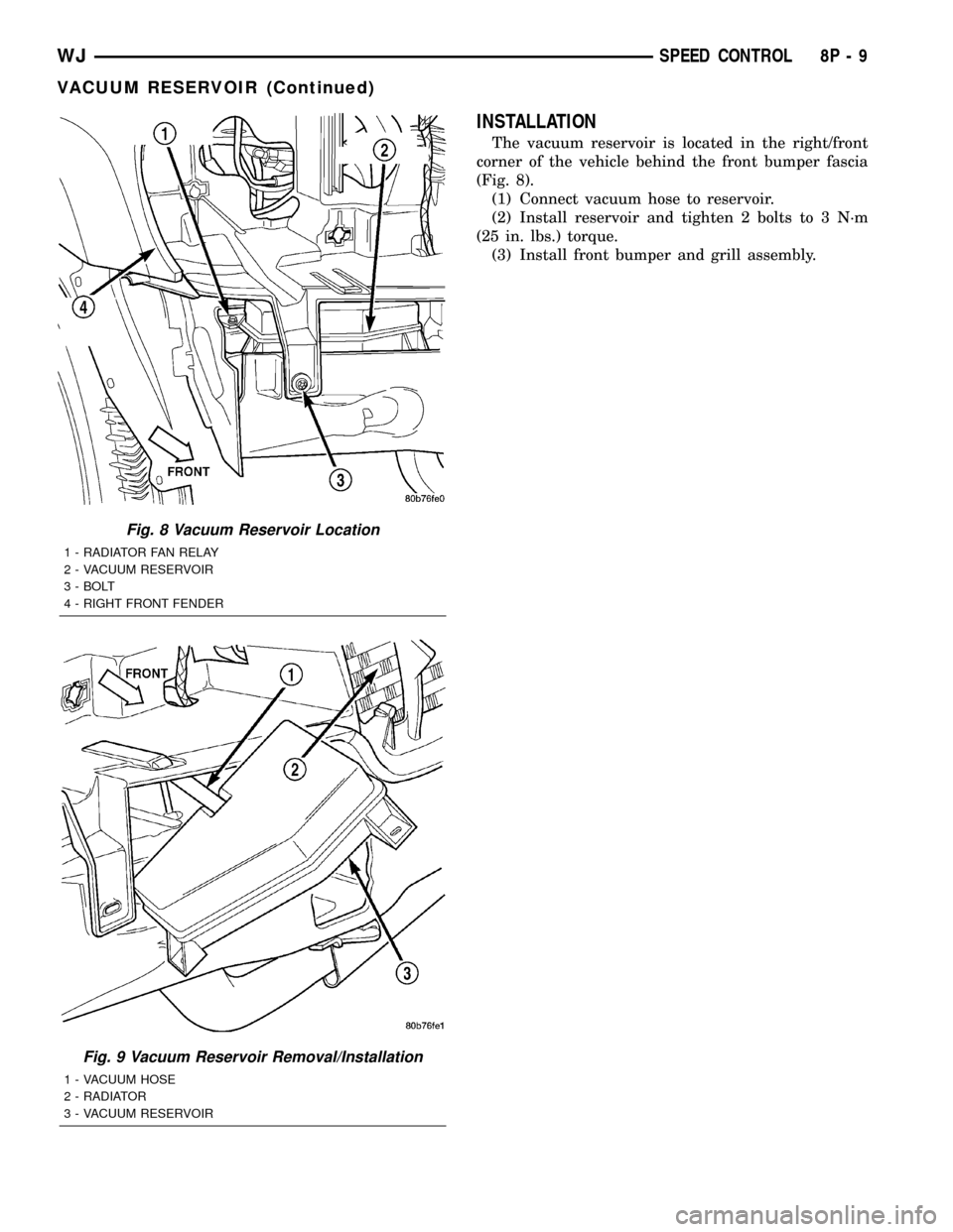
The vacuum reservoir is located in the right/front
corner of the vehicle behind the front bumper fascia
(Fig. 8).
(1) Remove front bumper and grill assembly.
(2) Remove 1 support bolt near front of reservoir
(Fig. 8).
(3) Remove 2 reservoir mounting bolts.
(4) Remove reservoir from vehicle to gain access to
vacuum hose (Fig. 9). Disconnect vacuum hose from
reservoir fitting at rear of reservoir.
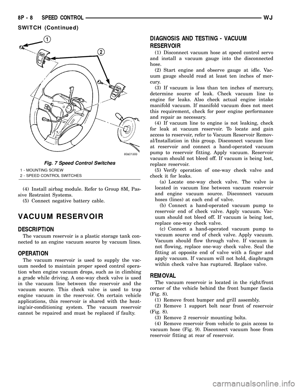
Fig. 7 Speed Control Switches
1 - MOUNTING SCREW
2 - SPEED CONTROL SWITCHES
8P - 8 SPEED CONTROLWJ
SWITCH (Continued)
Page 590 of 2199
INSTALLATION
The vacuum reservoir is located in the right/front
corner of the vehicle behind the front bumper fascia
(Fig. 8).
(1) Connect vacuum hose to reservoir.
(2) Install reservoir and tighten 2 bolts to 3 N´m
(25 in. lbs.) torque.
(3) Install front bumper and grill assembly.
Fig. 8 Vacuum Reservoir Location
1 - RADIATOR FAN RELAY
2 - VACUUM RESERVOIR
3 - BOLT
4 - RIGHT FRONT FENDER
Fig. 9 Vacuum Reservoir Removal/Installation
1 - VACUUM HOSE
2 - RADIATOR
3 - VACUUM RESERVOIR
WJSPEED CONTROL 8P - 9
VACUUM RESERVOIR (Continued)
Page 1186 of 2199
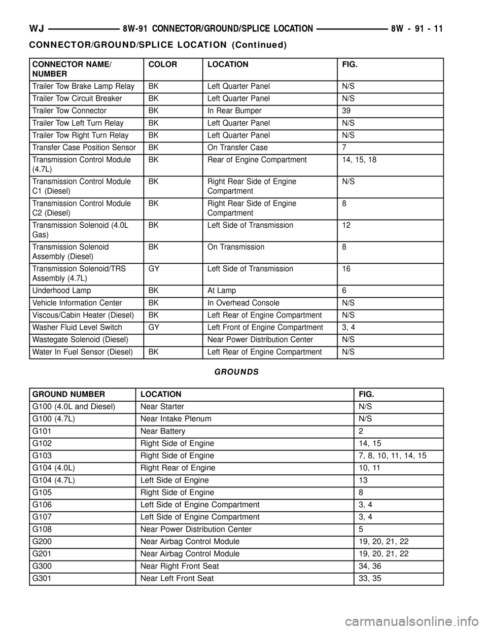
CONNECTOR NAME/
NUMBERCOLOR LOCATION FIG.
Trailer Tow Brake Lamp Relay BK Left Quarter Panel N/S
Trailer Tow Circuit Breaker BK Left Quarter Panel N/S
Trailer Tow Connector BK In Rear Bumper 39
Trailer Tow Left Turn Relay BK Left Quarter Panel N/S
Trailer Tow Right Turn Relay BK Left Quarter Panel N/S
Transfer Case Position Sensor BK On Transfer Case 7
Transmission Control Module
(4.7L)BK Rear of Engine Compartment 14, 15, 18
Transmission Control Module
C1 (Diesel)BK Right Rear Side of Engine
CompartmentN/S
Transmission Control Module
C2 (Diesel)BK Right Rear Side of Engine
Compartment8
Transmission Solenoid (4.0L
Gas)BK Left Side of Transmission 12
Transmission Solenoid
Assembly (Diesel)BK On Transmission 8
Transmission Solenoid/TRS
Assembly (4.7L)GY Left Side of Transmission 16
Underhood Lamp BK At Lamp 6
Vehicle Information Center BK In Overhead Console N/S
Viscous/Cabin Heater (Diesel) BK Left Rear of Engine Compartment N/S
Washer Fluid Level Switch GY Left Front of Engine Compartment 3, 4
Wastegate Solenoid (Diesel) Near Power Distribution Center N/S
Water In Fuel Sensor (Diesel) BK Left Rear of Engine Compartment N/S
GROUNDS
GROUND NUMBER LOCATION FIG.
G100 (4.0L and Diesel) Near Starter N/S
G100 (4.7L) Near Intake Plenum N/S
G101 Near Battery 2
G102 Right Side of Engine 14, 15
G103 Right Side of Engine 7, 8, 10, 11, 14, 15
G104 (4.0L) Right Rear of Engine 10, 11
G104 (4.7L) Left Side of Engine 13
G105 Right Side of Engine 8
G106 Left Side of Engine Compartment 3, 4
G107 Left Side of Engine Compartment 3, 4
G108 Near Power Distribution Center 5
G200 Near Airbag Control Module 19, 20, 21, 22
G201 Near Airbag Control Module 19, 20, 21, 22
G300 Near Right Front Seat 34, 36
G301 Near Left Front Seat 33, 35
WJ8W-91 CONNECTOR/GROUND/SPLICE LOCATION 8W - 91 - 11
CONNECTOR/GROUND/SPLICE LOCATION (Continued)