lock JEEP GRAND CHEROKEE 2008 WK / 3.G SRT Owner's Guide
[x] Cancel search | Manufacturer: JEEP, Model Year: 2008, Model line: GRAND CHEROKEE, Model: JEEP GRAND CHEROKEE 2008 WK / 3.GPages: 405, PDF Size: 2.93 MB
Page 108 of 405
4 - Way Passenger's Power Seat Ð If Equipped
The front passenger's power seat switches are located on
the outboard side of the passenger seat lower side trim.
The bottom switch controls forward/rearward adjust-
ment. The top switch controls the seatback recline adjust-
ment.
NOTE:The 4 - way seat does not have an up/down
adjustment.
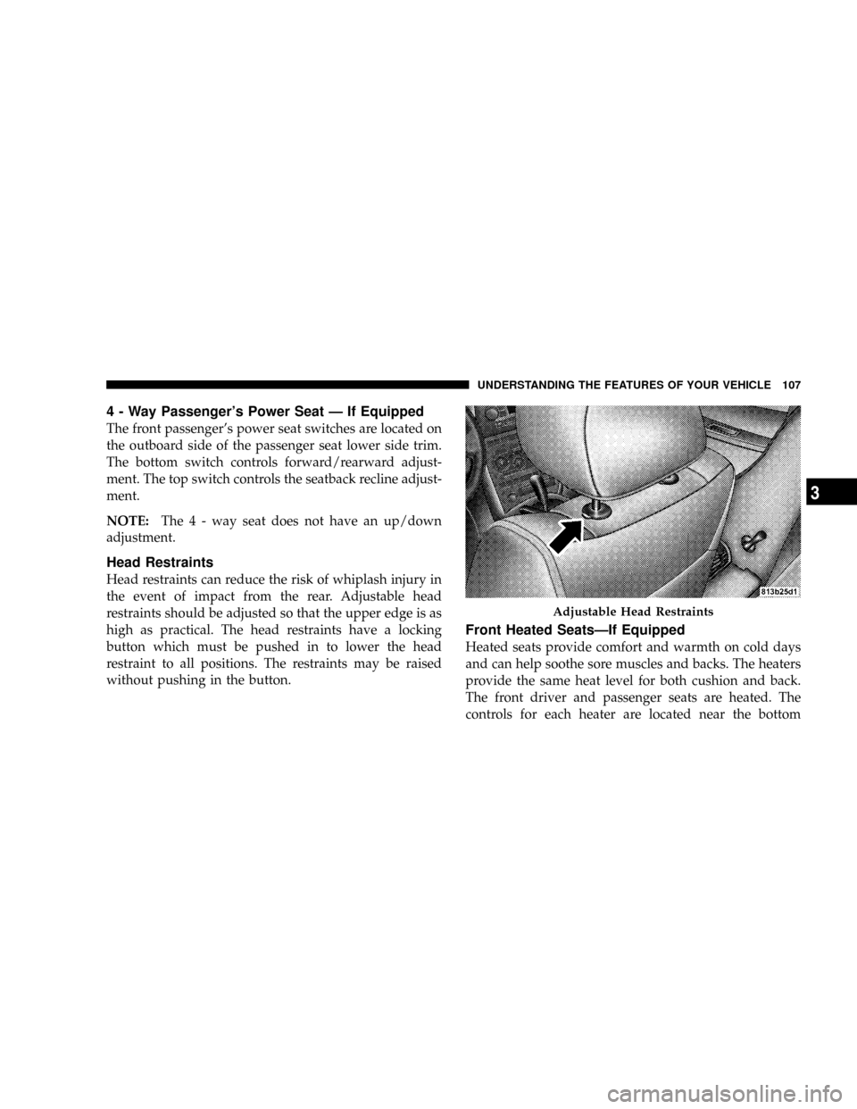
Head Restraints
Head restraints can reduce the risk of whiplash injury in
the event of impact from the rear. Adjustable head
restraints should be adjusted so that the upper edge is as
high as practical. The head restraints have a locking
button which must be pushed in to lower the head
restraint to all positions. The restraints may be raised
without pushing in the button.
Front Heated SeatsÐIf Equipped
Heated seats provide comfort and warmth on cold days
and can help soothe sore muscles and backs. The heaters
provide the same heat level for both cushion and back.
The front driver and passenger seats are heated. The
controls for each heater are located near the bottom
Adjustable Head Restraints
UNDERSTANDING THE FEATURES OF YOUR VEHICLE 107
3
Page 113 of 405
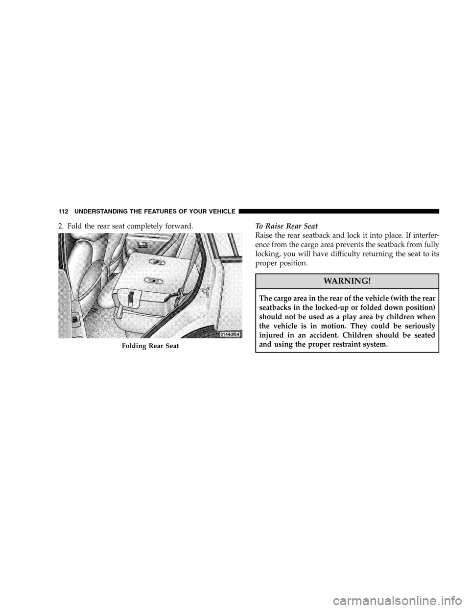
2. Fold the rear seat completely forward.To Raise Rear Seat
Raise the rear seatback and lock it into place. If interfer-
ence from the cargo area prevents the seatback from fully
locking, you will have difficulty returning the seat to its
proper position.
WARNING!
The cargo area in the rear of the vehicle (with the rear
seatbacks in the locked-up or folded down position)
should not be used as a play area by children when
the vehicle is in motion. They could be seriously
injured in an accident. Children should be seated
and using the proper restraint system.
Folding Rear Seat
112 UNDERSTANDING THE FEATURES OF YOUR VEHICLE
Page 115 of 405
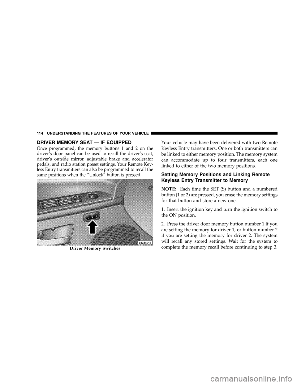
DRIVER MEMORY SEAT Ð IF EQUIPPED
Once programmed, the memory buttons 1 and 2 on the
driver's door panel can be used to recall the driver's seat,
driver's outside mirror, adjustable brake and accelerator
pedals, and radio station preset settings. Your Remote Key-
less Entry transmitters can also be programmed to recall the
same positions when the ªUnlockº button is pressed.
Your vehicle may have been delivered with two Remote
Keyless Entry transmitters. One or both transmitters can
be linked to either memory position. The memory system
can accommodate up to four transmitters, each one
linked to either of the two memory positions.
Setting Memory Positions and Linking Remote
Keyless Entry Transmitter to Memory
NOTE:Each time the SET (S) button and a numbered
button (1 or 2) are pressed, you erase the memory settings
for that button and store a new one.
1. Insert the ignition key and turn the ignition switch to
the ON position.
2. Press the driver door memory button number 1 if you
are setting the memory for driver 1, or button number 2
if you are setting the memory for driver 2. The system
will recall any stored settings. Wait for the system to
complete the memory recall before continuing to step 3.
Driver Memory Switches
114 UNDERSTANDING THE FEATURES OF YOUR VEHICLE
Page 116 of 405
3. Adjust the driver's seat, recliner, and driver's side
view mirror to the desired positions.
4. Adjust the brake and accelerator pedals to the desired
positions.
5. Turn on the radio and set the radio station presets (up
to 10 AM and 10 FM stations can be set).
6. Turn the ignition switch to the LOCK position and
remove the key.
7. Press and release the SET (S) button located on the
driver's door.
8. Within 5 seconds, press and release memory button 1
or 2 on the driver's door. The next step must be per-
formed within 5 seconds if you desire to also use a
Remote Keyless Entry transmitter to recall memory po-
sitions.9. Press and release the ªLockº button on one of the
transmitters.
10. Insert the ignition key and turn the ignition switch to
the ON position.
11. Select9Remote Linked to Memory9in the Electronic
Vehicle Information Center (EVIC) and enter9Ye s9or
select9Use Factory Settings9from the EVIC and enter
9Ye s9. Refer to ªElectronic Vehicle Information Center
(EVIC) Ð Customer Programmable Featuresº in Section
4 for more information.
12. Repeat the above steps to set the next memory
position using the other numbered memory button or to
link another Remote Keyless Entry transmitter to
memory.
UNDERSTANDING THE FEATURES OF YOUR VEHICLE 115
3
Page 117 of 405
Memory Position Recall
NOTE:The vehicle must be in P (Park) to recall memory
positions. If a recall is attempted when the vehicle is not
in P (Park), a message will be displayed in the Electronic
Vehicle Information Center (EVIC).
To recall the memory settings for driver one, press
memory button number 1 on the driver's door or the
ªUnlockº button on the Remote Keyless Entry transmit-
ter linked to memory position 1.
To recall the memory setting for driver two, press
memory button number 2 on the driver's door or the
ªUnlockº button on the Remote Keyless Entry transmit-
ter linked to memory position 2.
A recall can be cancelled by pressing any of the memory
buttons on the drivers door during a recall (S, 1, or 2).
When a recall is cancelled, the driver's seat, driver'smirror, and the pedals stop moving. A delay of one
second will occur before another recall can be selected.
To Disable A Transmitter Linked to Memory
1. Turn the ignition switch to the LOCK position and
remove the key.
2. Press and release memory button number 1. The
system will recall any memory settings stored in position
1. Wait for the system to complete the memory recall
before continuing to step 3.
3. Press and release the memory SET (S) button located
on the driver's door.
4. Within 5 seconds, press and release memory button 1
on the driver's door.
5. Within 5 seconds, press and release the ªUnlockº
button on the Remote Keyless Entry transmitter.
116 UNDERSTANDING THE FEATURES OF YOUR VEHICLE
Page 118 of 405
To disable another transmitter linked to either memory
position, repeat steps 1-5 for each transmitter.
NOTE:Once programmed, all transmitters linked to
memory can be easily enabled or disabled at one time.
Refer to Remote Linked to Memory under9Electronic
Vehicle Information Center (EVIC) Ð Customer Pro-
grammable Features9in Section 4 for more information.
Easy Entry/Exit Seat
This feature provides automatic driver's seat positioning
which will enhance driver mobility out of and into the
vehicle.
There are two possible Easy Exit and Easy Entry adjust-
ments available:
²The seat cushion will move rearward approximately
2.5 inches (60 mm) if the starting position of the seat is
greater than or equal to 2.67 inches (68 mm) forward of
the rear seat stop when the key is removed from theignition switch. The seat will then move forward
approximately 2.5 inches (60 mm) when the key is
placed into the ignition and turned out of the LOCK
position.
²The seat shall move to the position located 0.3 inches
(8 mm) forward of the rear stop if the starting position
is between 0.9 inches to 2.67 inches (23 mm to 68 mm)
forward of the rear stop when the key is removed from
the ignition switch. The seat will move forward to the
memory/driving position when the key is placed into
the ignition, and turned out of the LOCK position
toward the ACC/ON position.
The Easy Entry/Easy Exit feature will be automatically
disabled if the seat is already positioned closer than 0.9
inches (23 mm) forward of the rear stop. At this position
there is no benefit to the driver by moving the seat for
Easy Exit or Easy Entry.
UNDERSTANDING THE FEATURES OF YOUR VEHICLE 117
3
Page 120 of 405
WARNING!
If the hood is not fully latched, it could fly up when
the vehicle is moving and block your forward vision.
Be sure all hood latches are fully latched before
driving.
LIGHTS
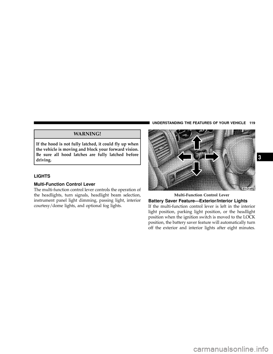
Multi-Function Control Lever
The multi-function control lever controls the operation of
the headlights, turn signals, headlight beam selection,
instrument panel light dimming, passing light, interior
courtesy/dome lights, and optional fog lights.
Battery Saver FeatureÐExterior/Interior Lights
If the multi-function control lever is left in the interior
light position, parking light position, or the headlight
position when the ignition switch is moved to the LOCK
position, the battery saver feature will automatically turn
off the exterior and interior lights after eight minutes.
Multi-Function Control Lever
UNDERSTANDING THE FEATURES OF YOUR VEHICLE 119
3
Page 124 of 405
even when the doors and liftgate are open. While in the
ªOffº position the instrument panel lighting is at the
lowest light level and may not be suitable for night
driving.
Daytime Running Lights Ð If Equipped
The high beam headlights come on at a low intensity
level whenever the engine is running, and the transmis-
sion in not in the P (Park) position. The lights will remain
on until the ignition switch is turned to LOCK/ACC, or
the parking brake is engaged. The headlight switch must
be used for normal night time driving.
Automatic Headlight Leveling Ð HID Headlights
Only
This feature prevents the headlights from interfering
with the vision of oncoming drivers. Headlight leveling
automatically adjusts the height of the headlight beam in
reaction to changes in vehicle pitch.
Lights-On Reminder
If the headlights or parking lights are on after the ignition
switch has been turned to LOCK/ACC, a chime will
sound when the driver's door is opened.
Fog Lights Ð If Equipped
The fog light switch is located in the multi-
function control lever. To activate the fog lights,
turn on the park/turn lights, low beam headlights,
or ªAutoº headlights and pull out the end of the multi-
function control lever. A light in the instrument cluster
shows when the fog lights are on.
NOTE:Turning on the high beam headlights turns off
the fog lights.
A front fog light is a lighting device providing illumina-
tion forward of the vehicle under conditions of fog, rain,
snow, or dust. Principally, the front fog light supplements
the lower beam of a standard headlight system.
UNDERSTANDING THE FEATURES OF YOUR VEHICLE 123
3
Page 125 of 405
NOTE:Proper aim and adjustments of the front fog
lights should be made to prevent excessive glare for other
drivers.
Turn Signals
Move the multi-function control lever up or down and
the arrows on each side of the instrument cluster will
flash to show proper operation of the front and rear turn
signal lights. You can signal a lane change by moving the
lever partially up or down.
Turn Signal Auto-Mode
Tap the multi-function control lever once and the turn
signal (left or right) will flash 3 times, and automatically
turn off.
High Beam Switch
Push the multi-function control lever away from you to
switch the headlights to high beam. Pull the lever to-
wards you to switch the headlights back to low beam.
Passing Light
You can signal another vehicle with your headlights by
lightly pulling the multi-function control lever toward
the steering wheel. This will cause the headlights to turn
on at high beam and remain on until the lever is released.
Headlight Time Delay
There is also a feature that delays turning off the vehicle
lights for 30, 60, or 90 seconds after the ignition switch is
turned OFF. To activate the headlight delay, the multi-
function control lever must be rotated to the ªOffº
position after the ignition switch is turned to LOCK/
ACC. Only the headlights will illuminate during this
124 UNDERSTANDING THE FEATURES OF YOUR VEHICLE
Page 130 of 405
²Low Ambient TemperatureÐ When the ignition is
first turned ON, the rain sensing system will not
operate until the wiper switch is moved, vehicle speed
is greater than 0 mph (0 km/h), or the outside tem-
perature is greater than 32ÉF (0ÉC).
²Transmission in N (Neutral) PositionÐ When the
ignition is ON, and the transmission is in the N
(Neutral) position, the rain sensing system will not
operate until the wiper switch is moved, vehicle speed
is greater than 5 mph (8 km/h), or the shift lever is
moved out of the N (Neutral) position.
TILT/TELESCOPING STEERING COLUMN
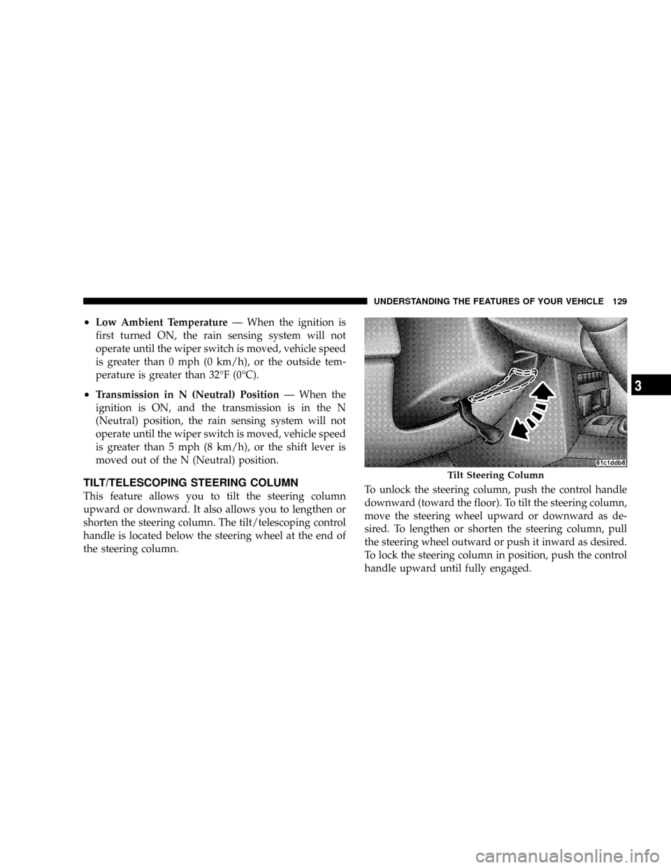
This feature allows you to tilt the steering column
upward or downward. It also allows you to lengthen or
shorten the steering column. The tilt/telescoping control
handle is located below the steering wheel at the end of
the steering column.To unlock the steering column, push the control handle
downward (toward the floor). To tilt the steering column,
move the steering wheel upward or downward as de-
sired. To lengthen or shorten the steering column, pull
the steering wheel outward or push it inward as desired.
To lock the steering column in position, push the control
handle upward until fully engaged.
Tilt Steering Column
UNDERSTANDING THE FEATURES OF YOUR VEHICLE 129
3