brakes JEEP GRAND CHEROKEE 2012 WK2 / 4.G SRT Owners Manual
[x] Cancel search | Manufacturer: JEEP, Model Year: 2012, Model line: GRAND CHEROKEE, Model: JEEP GRAND CHEROKEE 2012 WK2 / 4.GPages: 572, PDF Size: 8.69 MB
Page 206 of 572

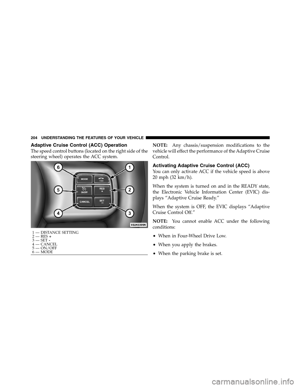
Adaptive Cruise Control (ACC) Operation
The speed control buttons (located on the right side of the
steering wheel) operates the ACC system.NOTE:Any chassis/suspension modifications to the
vehicle will effect the performance of the Adaptive Cruise
Control.
Activating Adaptive Cruise Control (ACC)
You can only activate ACC if the vehicle speed is above
20 mph (32 km/h).
When the system is turned on and in the READY state,
the Electronic Vehicle Information Center (EVIC) dis-
plays “Adaptive Cruise Ready.”
When the system is OFF, the EVIC displays “Adaptive
Cruise Control Off.”
NOTE:You cannot enable ACC under the following
conditions:
•When in Four-Wheel Drive Low.
•When you apply the brakes.
•When the parking brake is set.
1 — DISTANCE SETTING
2 — RES+
3 — SET-
4 — CANCEL
5 — ON/OFF
6 — MODE 204 UNDERSTANDING THE FEATURES OF YOUR VEHICLE
Page 214 of 572

The maximum braking applied by ACC is limited; how-
ever, the driver can always apply the brakes manually, if
necessary.
NOTE:The brake lights will illuminate whenever the
ACC system applies the brakes.
A Proximity Warning will alert the driver if ACC predicts
that its maximum braking level is not sufficient to
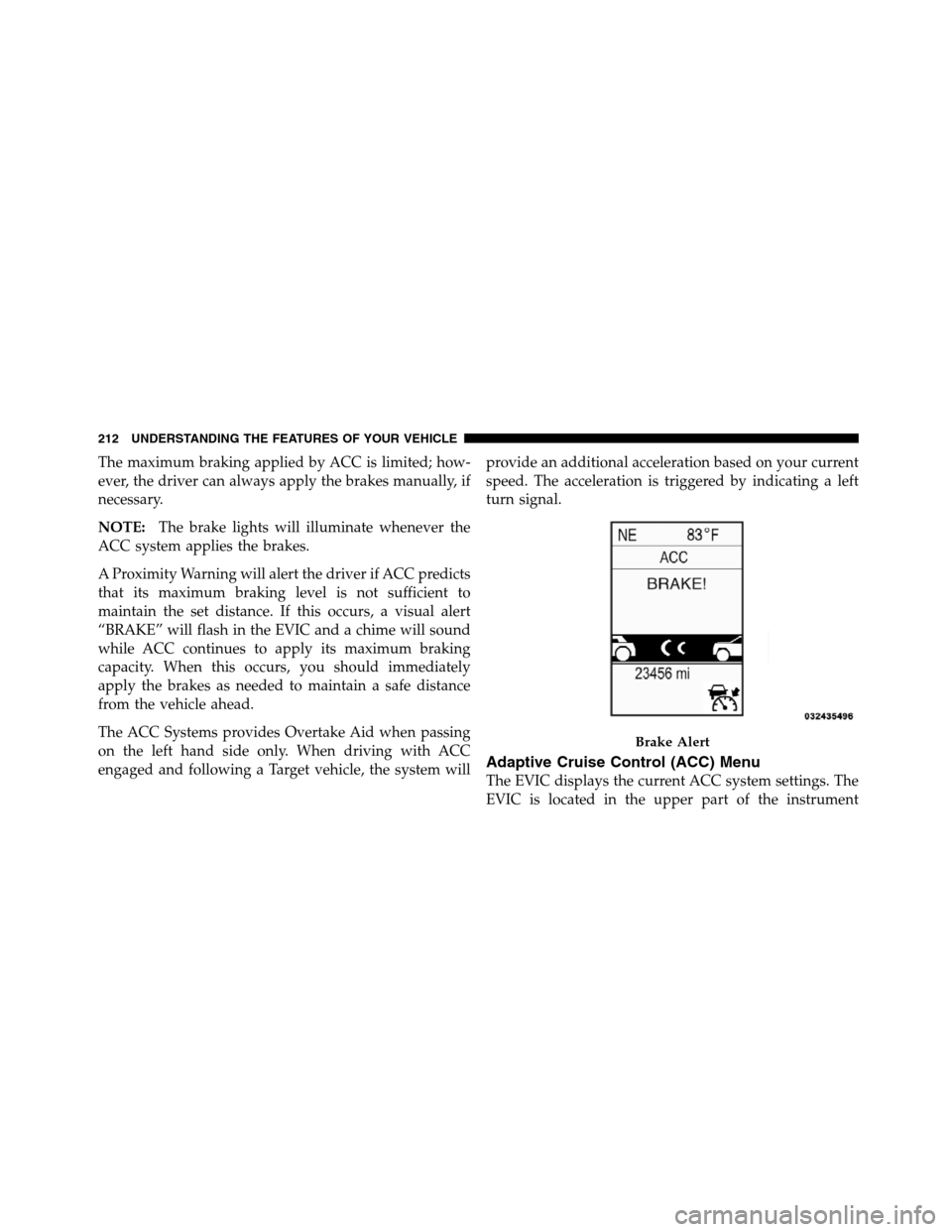
maintain the set distance. If this occurs, a visual alert
“BRAKE” will flash in the EVIC and a chime will sound
while ACC continues to apply its maximum braking
capacity. When this occurs, you should immediately
apply the brakes as needed to maintain a safe distance
from the vehicle ahead.
The ACC Systems provides Overtake Aid when passing
on the left hand side only. When driving with ACC
engaged and following a Target vehicle, the system willprovide an additional acceleration based on your current
speed. The acceleration is triggered by indicating a left
turn signal.
Adaptive Cruise Control (ACC) Menu
The EVIC displays the current ACC system settings. The
EVIC is located in the upper part of the instrument
Brake Alert
212 UNDERSTANDING THE FEATURES OF YOUR VEHICLE
Page 222 of 572

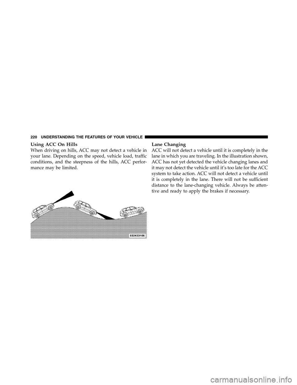
Using ACC On Hills
When driving on hills, ACC may not detect a vehicle in
your lane. Depending on the speed, vehicle load, traffic
conditions, and the steepness of the hills, ACC perfor-
mance may be limited.
Lane Changing
ACC will not detect a vehicle until it is completely in the
lane in which you are traveling. In the illustration shown,
ACC has not yet detected the vehicle changing lanes and
it may not detect the vehicle until it’s too late for the ACC
system to take action. ACC will not detect a vehicle until
it is completely in the lane. There will not be sufficient
distance to the lane-changing vehicle. Always be atten-
tive and ready to apply the brakes if necessary.
220 UNDERSTANDING THE FEATURES OF YOUR VEHICLE
Page 224 of 572

Stationary Objects And Vehicles
ACC does not react to stationary objects and stationary
vehicles. For example, ACC will not react in situations
where the vehicle you are following exits your lane and
the vehicle ahead is stopped in your lane. Always be
attentive and ready to apply the brakes if necessary.
General Information
FCC Requirements For Vehicular Radar Systems
Classification Specifications:
47 C.F.R. Part 15
47 C.F.R Part 15.515
Normal (Fixed Speed) Cruise Control Mode
In addition to Adaptive Cruise Control mode, a normal
(fixed speed) Cruise Control mode is available for cruis-
ing at fixed speeds. The normal Cruise Control mode is
designed to maintain a set cruising speed without requir-
ing the driver to operate the accelerator. Cruise Control
can only be operated if the vehicle speed is above 20 mph
(32 km/h).
To change between the different cruise modes, press the
MODE button when the system is in either the OFF,
READY or SET state. Pressing of the MODE button in any
state will result in changing to the new Mode in the OFF
state.
222 UNDERSTANDING THE FEATURES OF YOUR VEHICLE
Page 293 of 572

The light also will turn on when the parking brake is
applied with the ignition switch in the ON/RUN posi-
tion.
NOTE:This light shows only that the parking brake is
applied. It does not show the degree of brake application.
15. Anti-Lock Brake (ABS) Light
This light monitors the Anti-Lock Brake System
(ABS). The light will turn on when the ignition
switch is turned to the ON/RUN position and
may stay on for as long as four seconds.
If the ABS light remains on or turns on while driving, it
indicates that the Anti-Lock portion of the brake system
is not functioning and that service is required. However,
the conventional brake system will continue to operate
normally if the BRAKE warning light is not on.
If the ABS light is on, the brake system should be serviced
as soon as possible to restore the benefits of Anti-Lockbrakes. If the ABS light does not turn on when the
ignition switch is turned to the ON/RUN position, have
the light inspected by an authorized dealer.
16. Speedometer
Indicates vehicle speed.
17. Sport Mode
This light will illuminate when the sport mode
or track mode is selected. These modes provide
performance based tuning with improved han-
dling and acceleration through an electronic
controlled dampening system. This system reduces body
roll and pitch in many driving situations including
cornering, acceleration and braking.
18. Fuel Door Reminder
The fuel pump symbol points to the side of the
vehicle where the fuel door is located.
4
UNDERSTANDING YOUR INSTRUMENT PANEL 291
Page 300 of 572

momentarily. Refer to “Adaptive Cruise Control
(ACC)” in “Understanding The Features Of Your
Vehicle” (if equipped).
•Brake — If the ACC system predicts that its maximum
braking level is not sufficient to maintain the set
distance, this message will flash and a chime will
sound while ACC continues to apply its maximum
braking capacity. When this occurs, you should imme-
diately apply the brakes as needed to maintain a safe
distance from the vehicle ahead. Refer to “Adaptive
Cruise Control (ACC)” in “Understanding The Fea-
tures Of Your Vehicle” (if equipped).
•Clean Radar Sensor in the Front of Vehicle — If the
ACC system deactivates due to performance limiting
conditions. Refer to “Adaptive Cruise Control (ACC)”
in “Understanding The Features Of Your Vehicle” (if
equipped).
•ACC/FCW Unavailable Vehicle System Error — If the
ACC system turns off due to a temporary malfunction
that limits functionality. Refer to “Adaptive Cruise
Control (ACC)” in “Understanding The Features Of
Your Vehicle” (if equipped).
•ACC/FCW Unavailable Service Radar Sensor — If the
ACC system turns off due to an internal system fault
that requires service from an authorized dealer. Refer
to “Adaptive Cruise Control (ACC)” in “Understand-
ing The Features Of Your Vehicle” (if equipped).
•Cruise Off When Park Brake is On
•ACC Cancelled Below Min. Speed.
•Coolant low
•Service air suspension system
•Oil change due
•Key in ignition
298 UNDERSTANDING YOUR INSTRUMENT PANEL
Page 377 of 572

STARTING PROCEDURES
Before starting your vehicle, adjust your seat, adjust the
inside and outside mirrors, fasten your seat belt, and if
present, instruct all other occupants to buckle their seat
belts.
WARNING!
•When leaving the vehicle, always remove the key
fob from the ignition and lock your vehicle.
•Never leave children alone in a vehicle, or with
access to an unlocked vehicle. Allowing children
to be in a vehicle unattended is dangerous for a
number of reasons. A child or others could be
seriously or fatally injured. Children should be
warned not to touch the parking brake, brake
pedal or the shift lever.
(Continued)
WARNING! (Continued)
•Do not leave the key fob in or near the vehicle, and
do not leave Keyless Enter-N-Go in the ACC or
ON/RUN mode. A child could operate power win-
dows, other controls, or move the vehicle.
Automatic Transmission
The shift lever must be in the NEUTRAL or PARK
position before you can start the engine. Apply the brakes
before shifting into any driving gear.
CAUTION!
Damage to the transmission may occur if the follow-
ing precautions are not observed:
•Shift into PARK only after the vehicle has come to
a complete stop.
(Continued)
5
STARTING AND OPERATING 375
Page 384 of 572

WARNING! (Continued)
•Unintended movement of a vehicle could injure
those in or near the vehicle. As with all vehicles,
you should never exit a vehicle while the engine is
running. Before exiting a vehicle, always apply the
parking brake, shift the transmission into PARK,
and remove the key fob. Once the key fob is
removed, the shift lever is locked in the PARK
position, securing the vehicle against unwanted
movement. Furthermore, you should never leave
unattended children inside a vehicle.
Key Ignition Park Interlock
This vehicle is equipped with a Key Ignition Park Inter-
lock which requires the shift lever to be placed in PARK
before the ignition switch can be turned to the LOCK/
OFF position. The key fob can only be removed from the
ignition when the ignition is in the LOCK/OFF position,
and once removed the shift lever is locked in PARK.
Brake/Transmission Shift Interlock System
This vehicle is equipped with a Brake Transmission Shift
Interlock (BTSI) system that holds the shift lever in the
PARK position unless the brakes are applied. To move
the shift lever out of the PARK position, the ignition
switch must be turned to the ON/RUN position (engine
running or not) and the brake pedal must be pressed.
Five-Speed Automatic Transmission
The shift lever position display (located in the instrument
panel cluster) indicates the transmission gear range. You
must press the brake pedal to move the shift lever out of
the PARK position (refer to “Brake/Transmission Shift
Interlock System” in this section). To drive, move the shift
lever from PARK or NEUTRAL to the DRIVE position.
The electronically-controlled transmission provides a
precise shift schedule. The transmission electronics are
self-calibrating; therefore, the first few shifts on a new
382 STARTING AND OPERATING
Page 398 of 572

WARNING!
•Driving through standing water limits your vehi-
cle’s traction capabilities. Do not exceed 5 mph
(8 km/h) when driving through standing water.
•Driving through standing water limits your vehi-
cle’s braking capabilities, which increases stop-
ping distances. Therefore, after driving through
standing water, drive slowly and lightly press on
the brake pedal several times to dry the brakes.
•Getting water inside your vehicle’s engine can
cause it to lock up and stall out, and leave you
stranded.
•Failure to follow these warnings may result in
injuries that are serious or fatal to you, your
passengers, and others around you.
POWER STEERING
The standard power steering system will give you good
vehicle response and increased ease of maneuverability
in tight spaces. The system will provide mechanical
steering capability if power assist is lost.
If for some reason the power assist is interrupted, it will
still be possible to steer your vehicle. Under these condi-
tions, you will observe a substantial increase in steering
effort, especially at very low vehicle speeds and during
parking maneuvers.
NOTE:
•Increased noise levels at the end of the steering wheel
travel are considered normal and do not indicate that
there is a problem with the power steering system.
•Upon initial start-up in cold weather, the power steer-
ing pump may make noise for a short amount of time.
This is due to the cold, thick fluid in the steering
system. This noise should be considered normal, and it
does not in any way damage the steering system.
396 STARTING AND OPERATING
Page 403 of 572

Differential (BLD), functions similar to a limited-slip
differential and controls the wheel spin across a driven
axle. If one wheel on a driven axle is spinning faster than
the other, the system will apply the brake of the spinning
wheel. This will allow more engine torque to be applied
to the wheel that is not spinning. This feature remains
active even if ESC system is in the “Partial Off” mode.
Refer to “Electronic Stability Control (ESC)” in this
section for further information.
Brake Assist System (BAS)
The BAS is designed to optimize the vehicle’s braking
capability during emergency braking maneuvers. The
system detects an emergency braking situation by sens-
ing the rate and amount of brake application and then
applies optimum pressure to the brakes. This can help
reduce braking distances. The BAS complements the
anti-lock brake system (ABS). Applying the brakes very
quickly results in the best BAS assistance. To receive thebenefit of the system, you must applycontinuousbrak-
ing pressure during the stopping sequence (do not
“pump” the brakes). Do not reduce brake pedal pressure
unless braking is no longer desired. Once the brake pedal
is released, the BAS is deactivated.
WARNING!
The BAS cannot prevent the natural laws of physics
from acting on the vehicle, nor can it increase the
traction afforded by prevailing road conditions. The
BAS cannot prevent collisions, including those re-
sulting from excessive speed in turns, driving on
very slippery surfaces, or hydroplaning. The capa-
bilities of a BAS-equipped vehicle must never be
exploited in a reckless or dangerous manner which
could jeopardize the user’s safety or the safety of
others.
5
STARTING AND OPERATING 401