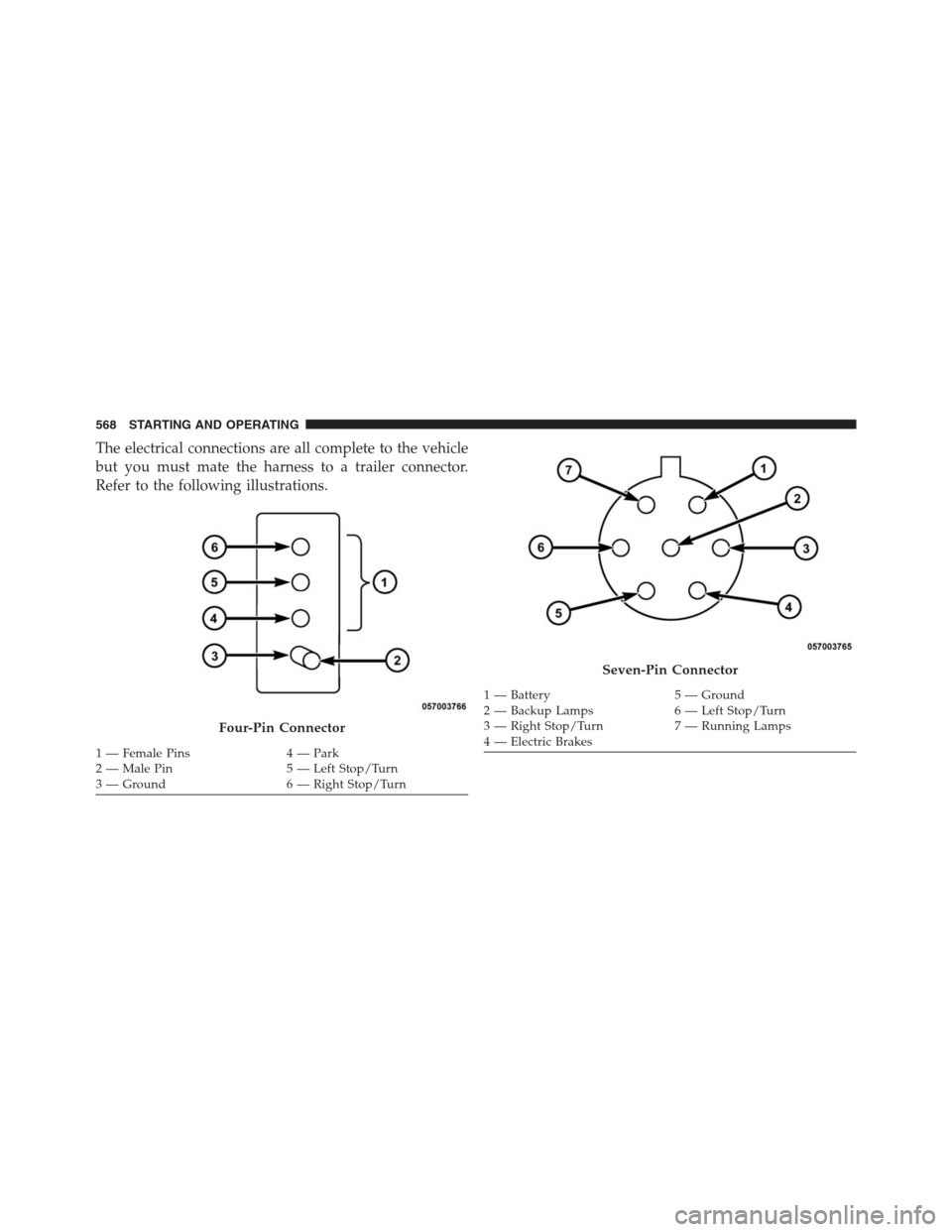
The electrical connections are all complete to the vehicle
but you must mate the harness to a trailer connector.
Refer to the following illustrations.
Four-Pin Connector
1 — Female Pins 4 — Park
2 — Male Pin 5 — Left Stop/Turn
3 — Ground 6 — Right Stop/Turn
Seven-Pin Connector
1 — Battery 5 — Ground
2 — Backup Lamps 6 — Left Stop/Turn
3 — Right Stop/Turn 7 — Running Lamps
4 — Electric Brakes 568 STARTING AND OPERATING
WARNING!
Riding the brakes can lead to brake failure and
possibly a collision. Driving with your foot resting or
riding on the brake pedal can result in abnormally
high brake temperatures, excessive lining wear, and
possible brake damage. You would not have your full
braking capacity in an emergency.
Fluid Level Check – Brake Master Cylinder
The fluid level of the master cylinder should be checked
when performing under the hood service, or immedi-
ately if the brake system warning lamp indicates system
failure.
The brake master cylinder has a plastic reservoir. On the
outboard side of the reservoir, there is a “MAX” dot and
a “MIN” dot. The fluid level must be kept within these
two dots. Do not add fluid above the MAX mark, because
leakage may occur at the cap.With disc brakes, the fluid level can be expected to fall as
the brake linings wear. However, an unexpected drop in
fluid level may be caused by a leak and a system check
should be conducted.
Refer to “Fluids, Lubricants, and Genuine Parts” in
“Maintaining Your Vehicle” for further information.
WARNING!
•Use only manufacturer’s recommended brake
fluid. Refer to “Fluids, Lubricants, and Genuine
Parts” in “Maintaining Your Vehicle” for further
information. Using the wrong type of brake fluid
can severely damage your brake system and/or
impair its performance. The proper type of brake
fluid for your vehicle is also identified on the
original factory installed hydraulic master cylinder
reservoir.
(Continued)
7
MAINTAINING YOUR VEHICLE 633
Cavity Car-
tridge
FuseMini
FuseDescription
J01 40 Amp
GreenAir Suspension
J02 30 Amp
PinkPower Liftgate
Module
J03 30 Amp
PinkTrailer Tow
J04 25 Amp
NaturalDriver Door Node
J05 25 Amp
NaturalPassenger Door
Node
J06 40 Amp
GreenAntilock Brakes
Pump/Stability
Control SystemCavity Car-
tridge
FuseMini
FuseDescription
J07 30 Amp
PinkAntilock Brakes
Valve/Stability
Control System
J08 40 Amp
GreenPower Seat
J09 30 Amp
PinkE-Brake
J10 30 Amp
PinkHeadlamp Wash
Relay Contact
J11 30 Amp
PinkDrive Train Control
Module
J12 30 Amp
PinkRear Defroster
646 MAINTAINING YOUR VEHICLE
Cavity Car-
tridge
FuseMini
FuseDescription
M34 10 Amp
RedPark Assist
Module/Climate
Control System
Module/Infra Red
Sensor/Compass
Module
M35 15 Amp
BlueLeft Rear
Parklamps
M36 20 Amp
YellowPower Outlet
M37 10 Amp
RedAntilock Brakes/
Stability Control
System Module
M38 25 Amp
NaturalAll Door Lock
&UnlockCAUTION!
•When installing the totally integrated power mod-
ule cover, it is important to ensure the cover is
properly positioned and fully latched. Failure to do
so may allow water to get into the totally integrated
power module and possibly result in a electrical
system failure.
•When replacing a blown fuse, it is important to use
only a fuse having the correct amperage rating. The
use of a fuse with a rating other than indicated may
result in a dangerous electrical system overload. If
a properly rated fuse continues to blow, it indicates
a problem in the circuit that must be corrected.
7
MAINTAINING YOUR VEHICLE 651