JEEP GRAND CHEROKEE 2013 WK2 / 4.G SRT Owners Manual
Manufacturer: JEEP, Model Year: 2013, Model line: GRAND CHEROKEE, Model: JEEP GRAND CHEROKEE 2013 WK2 / 4.GPages: 661, PDF Size: 4.79 MB
Page 321 of 661
Accordingly, when the low tire pressure telltale illumi-
nates, you should stop and check your tires as soon as
possible, and inflate them to the proper pressure. Driving
on a significantly under-inflated tire causes the tire to
overheat and can lead to tire failure. Under-inflation also
reduces fuel efficiency and tire tread life, and may affect
the vehicle’s handling and stopping ability.
Please note that the TPMS is not a substitute for proper
tire maintenance, and it is the driver ’s responsibility to
maintain correct tire pressure, even if under-inflation has
not reached the level to trigger illumination of the TPMS
low tire pressure telltale.
Your vehicle has also been equipped with a TPMS
malfunction indicator to indicate when the system is not
operating properly. The TPMS malfunction indicator is
combined with the low tire pressure telltale. When the
system detects a malfunction, the telltale will flash for
approximately one minute and then remain continuouslyilluminated. This sequence will continue upon subse-
quent vehicle start-ups as long as the malfunction exists.
When the malfunction indicator is illuminated, the sys-
tem may not be able to detect or signal low tire pressure
as intended. TPMS malfunctions may occur for a variety
of reasons, including the installation of replacement or
alternate tires or wheels on the vehicle that prevent the
TPMS from functioning properly. Always check the
TPMS malfunction telltale after replacing one or more
tires or wheels on your vehicle, to ensure that the
replacement or alternate tires and wheels allow the TPMS
to continue to function properly.
4
UNDERSTANDING YOUR INSTRUMENT PANEL 319
Page 322 of 661
CAUTION!
The TPMS has been optimized for the original
equipment tires and wheels. TPMS pressures and
warning have been established for the tire size
equipped on your vehicle. Undesirable system opera-
tion or sensor damage may result when using re-
placement equipment that is not of the same size,
type, and/or style. Aftermarket wheels can cause
sensor damage. Do not use tire sealant from a can or
balance beads if your vehicle is equipped with a
TPMS, as damage to the sensors may result.12. Park/Headlight ON Indicator — If Equipped
This indicator will illuminate when the park
lights or headlights are turned on.
13. Seat Belt Reminder Light When the ignition switch is first turned to the
ON/RUN position, this light will turn on for four
to eight seconds as a bulb check. During the bulb
check, if the driver’s seat belt is unbuckled, a chime will
sound. After the bulb check or when driving, if the driver
or front passenger seat belt remains unbuckled, the Seat
Belt Indicator Light will flash or remain on continuously.
Refer to “Occupant Restraints” in “Things To Know
Before Starting Your Vehicle” for further information.
320 UNDERSTANDING YOUR INSTRUMENT PANEL
Page 323 of 661
14. Brake Warning LightThis light monitors various brake functions,
including brake fluid level and parking brake
application. If the brake light turns on it may
indicate that the parking brake is applied, that
the brake fluid level is low, or that there is a problem with
the anti-lock brake system reservoir.
If the light remains on when the parking brake has been
disengaged, and the fluid level is at the full mark on the
master cylinder reservoir, it indicates a possible brake
hydraulic system malfunction or that a problem with the
Brake Booster has been detected by the Anti-Lock Brake
System (ABS) / Electronic Stability Control (ESC) system.
In this case, the light will remain on until the condition
has been corrected. If the problem is related to the brake
booster, the ABS pump will run when applying the brake
and a brake pedal pulsation may be felt during each stop. The dual brake system provides a reserve braking capac-
ity in the event of a failure to a portion of the hydraulic
system. A leak in either half of the dual brake system is
indicated by the Brake Warning Light, which will turn on
when the brake fluid level in the master cylinder has
dropped below a specified level.
The light will remain on until the cause is corrected.
NOTE:
The light may flash momentarily during sharp
cornering maneuvers, which change fluid level condi-
tions. The vehicle should have service performed, and
the brake fluid level checked.
If brake failure is indicated, immediate repair is neces-
sary.
4
UNDERSTANDING YOUR INSTRUMENT PANEL 321
Page 324 of 661
WARNING!
Driving a vehicle with the red brake light on is
dangerous. Part of the brake system may have failed.
It will take longer to stop the vehicle. You could have
a collision. Have the vehicle checked immediately.
Vehicles equipped with the Anti-Lock Brake System
(ABS), are also equipped with Electronic Brake Force
Distribution (EBD). In the event of an EBD failure, the
Brake Warning Light will turn on along with the ABS
Light. Immediate repair to the ABS system is required.
Operation of the Brake Warning Light can be checked by
turning the ignition switch from the OFF position to the
ON/RUN position. The light should illuminate for ap-
proximately two seconds. The light should then turn off
unless the parking brake is applied or a brake fault is
detected. If the light does not illuminate, have the light
inspected by an authorized dealer. The light also will turn on when the parking brake is
applied with the ignition switch in the ON/RUN posi-
tion.
NOTE:
This light shows only that the parking brake is
applied. It does not show the degree of brake application.
15. Anti-Lock Brake (ABS) Light
This light monitors the Anti-Lock Brake System
(ABS). The light will turn on when the ignition
switch is turned to the ON/RUN position and
may stay on for as long as four seconds.
If the ABS light remains on or turns on while driving, it
indicates that the Anti-Lock portion of the brake system
is not functioning and that service is required. However,
the conventional brake system will continue to operate
normally if the BRAKE warning light is not on.
If the ABS light is on, the brake system should be serviced
as soon as possible to restore the benefits of Anti-Lock
322 UNDERSTANDING YOUR INSTRUMENT PANEL
Page 325 of 661
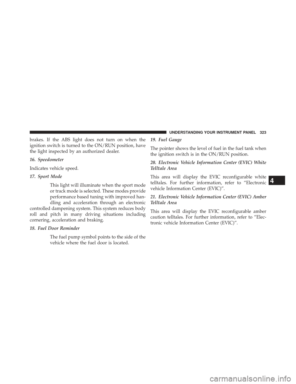
brakes. If the ABS light does not turn on when the
ignition switch is turned to the ON/RUN position, have
the light inspected by an authorized dealer.
16. Speedometer
Indicates vehicle speed.
17. Sport ModeThis light will illuminate when the sport mode
or track mode is selected. These modes provide
performance based tuning with improved han-
dling and acceleration through an electronic
controlled dampening system. This system reduces body
roll and pitch in many driving situations including
cornering, acceleration and braking.
18. Fuel Door Reminder
The fuel pump symbol points to the side of the
vehicle where the fuel door is located. 19. Fuel Gauge
The pointer shows the level of fuel in the fuel tank when
the ignition switch is in the ON/RUN position.
20. Electronic Vehicle Information Center (EVIC) White
Telltale Area
This area will display the EVIC reconfigurable white
telltales. For further information, refer to “Electronic
vehicle Information Center (EVIC)”.
21. Electronic Vehicle Information Center (EVIC) Amber
Telltale Area
This area will display the EVIC reconfigurable amber
caution telltales. For further information, refer to “Elec-
tronic vehicle Information Center (EVIC)”.
4
UNDERSTANDING YOUR INSTRUMENT PANEL 323
Page 326 of 661
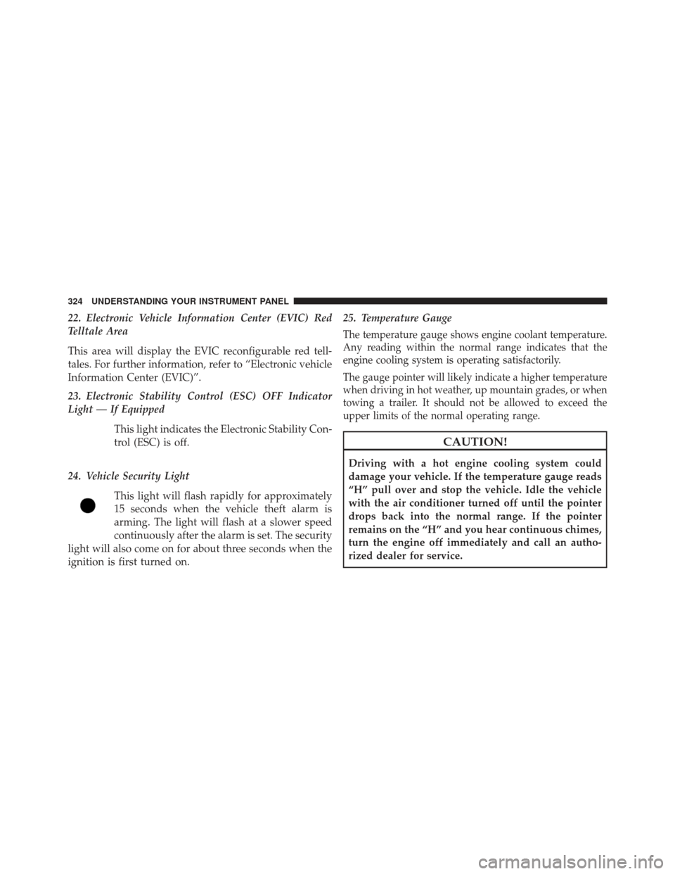
22. Electronic Vehicle Information Center (EVIC) Red
Telltale Area
This area will display the EVIC reconfigurable red tell-
tales. For further information, refer to “Electronic vehicle
Information Center (EVIC)”.
23. Electronic Stability Control (ESC) OFF Indicator
Light — If EquippedThis light indicates the Electronic Stability Con-
trol (ESC) is off.
24. Vehicle Security Light This light will flash rapidly for approximately
15 seconds when the vehicle theft alarm is
arming. The light will flash at a slower speed
continuously after the alarm is set. The security
light will also come on for about three seconds when the
ignition is first turned on. 25. Temperature Gauge
The temperature gauge shows engine coolant temperature.
Any reading within the normal range indicates that the
engine cooling system is operating satisfactorily.
The gauge pointer will likely indicate a higher temperature
when driving in hot weather, up mountain grades, or when
towing a trailer. It should not be allowed to exceed the
upper limits of the normal operating range.
CAUTION!
Driving with a hot engine cooling system could
damage your vehicle. If the temperature gauge reads
“H” pull over and stop the vehicle. Idle the vehicle
with the air conditioner turned off until the pointer
drops back into the normal range. If the pointer
remains on the “H” and you hear continuous chimes,
turn the engine off immediately and call an autho-
rized dealer for service.
324 UNDERSTANDING YOUR INSTRUMENT PANEL
Page 327 of 661
WARNING!
A hot engine cooling system is dangerous. You or
others could be badly burned by steam or boiling
coolant. You may want to call an authorized dealer
for service if your vehicle overheats. If you decide to
look under the hood yourself, see “Maintaining Your
Vehicle”. Follow the warnings under the Cooling
System Pressure Cap paragraph.
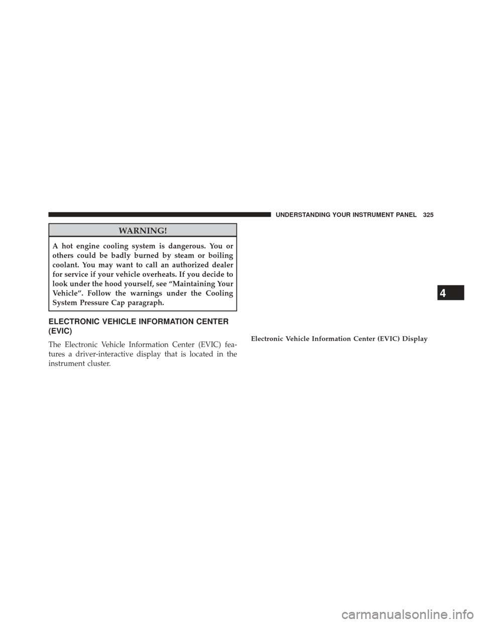
ELECTRONIC VEHICLE INFORMATION CENTER
(EVIC)
The Electronic Vehicle Information Center (EVIC) fea-
tures a driver-interactive display that is located in the
instrument cluster.Electronic Vehicle Information Center (EVIC) Display
4
UNDERSTANDING YOUR INSTRUMENT PANEL 325
Page 328 of 661
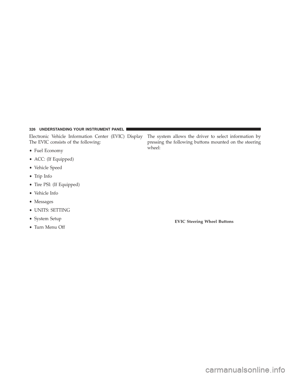
Electronic Vehicle Information Center (EVIC) Display
The EVIC consists of the following:
•Fuel Economy
• ACC: (If Equipped)
• Vehicle Speed
• Trip Info
• Tire PSI: (If Equipped)
• Vehicle Info
• Messages
• UNITS: SETTING
• System Setup
• Turn Menu Off The system allows the driver to select information by
pressing the following buttons mounted on the steering
wheel:
EVIC Steering Wheel Buttons
326 UNDERSTANDING YOUR INSTRUMENT PANEL
Page 329 of 661
UP ButtonPress and release the UP button to scroll up-
ward through the main menus (Fuel Economy,
Vehicle Info, Tire PSI, Cruise, Messages, Units,
System Setup, Vehicle Speed, Trip Info, Turn
Menu Off and sub-menus.
DOWN Button
Press and release the DOWN button to scroll
downward through the main menus and
sub-menus.
SELECT Button Press and release the SELECT button for access
to main menus, sub-menus or to select a per-
sonal setting in the setup menu. Press and hold
the SELECT button for two seconds to reset
features. BACK Button
Press the BACK button to scroll back to a
previous menu or sub-menu.
Electronic Vehicle Information Center (EVIC)
Displays
The EVIC display consists of three sections:
1. The top line where compass direction, odometer lineand outside temperature are displayed.
2. The main display area where the menus and pop up messages are displayed.
3. The reconfigurable telltales section below the odom- eter line.4
UNDERSTANDING YOUR INSTRUMENT PANEL 327
Page 330 of 661
The main display area will normally display the main
menu or the screens of a selected feature of the main
menu. The main display area also displays “pop up”
messages that consist of approximately 60 possible warn-
ing or information messages. These pop up messages fall
into several categories:
•Five Second Stored Messages
When the appropriate conditions occur, this type of
message takes control of the main display area for five
seconds and then returns to the previous screen. Most of
the messages of this type are then stored (as long as the
condition that activated it remains active) and can be
reviewed from the “Messages” main menu item. As long
as there is a stored message, an “i” will be displayed in
the EVIC’s compass/outside temp line. Examples of this
message type are”Right Front Turn Signal Lamp Out”
and “Low Tire Pressure”. •
Unstored Messages
This message type is displayed indefinitely or until the
condition that activated the message is cleared. Examples
of this message type are “Turn Signal On” (if a turn signal
is left on) and “Lights On” (if driver leaves the vehicle).
• Unstored Messages Until RUN
These messages deal primarily with the Remote Start
feature. This message type is displayed until the ignition
is in the RUN state. Examples of this message type are
“Remote Start Aborted - Door Ajar” and “Press Brake
Pedal and Push Button to Start”.
• Five Second Unstored
When the appropriate conditions occur, this type of mes-
sage takes control of the main display area for five seconds
and then returns to the previous screen. Examples of this
message type are “Memory System Unavailable - Not in
Park” and “Automatic High Beams On”.
328 UNDERSTANDING YOUR INSTRUMENT PANEL