sensor JEEP GRAND CHEROKEE 2014 WK2 / 4.G User Guide
[x] Cancel search | Manufacturer: JEEP, Model Year: 2014, Model line: GRAND CHEROKEE, Model: JEEP GRAND CHEROKEE 2014 WK2 / 4.GPages: 220, PDF Size: 6.12 MB
Page 36 of 220
ADAPTIVE CRUISE CONTROL (ACC)
If your vehicle is equipped with adaptive
cruise control the controls operate ex-
actly the same as the normal (fixed
speed) cruise control with one difference.
You can set a specified distance you
would like to maintain between you and
the vehicle in front of you.
If the ACC sensor detects a vehicle
ahead, ACC will apply limited braking or
acceleration automatically to maintain a
preset following distance, while match-
ing the speed of the vehicle ahead.
If the sensor does not detect a vehicle
ahead of you, ACC will maintain a fixed
set speed.
ACC ON/OFF
• Push and release the Adaptive Cruise Control (ACC) ON/OFF button.
ACC READY will appear on the instrument cluster to indicate the ACC is on.
• Push and release the Adaptive Cruise Control (ACC) ON/OFF button a second time
to turn the system off.
Adaptive Cruise Control (ACC) Off will appear on the instrument cluster to indicate
the ACC is off.
Distance Setting (ACC Only)
The specified following distance for ACC can be set by varying the distance setting
between four bars (longest), three bars (long), two bars (medium) and one bar (short).
Using this distance setting and the vehicle speed, ACC calculates and sets the
distance to the vehicle ahead. This distance setting displays in the EVIC.
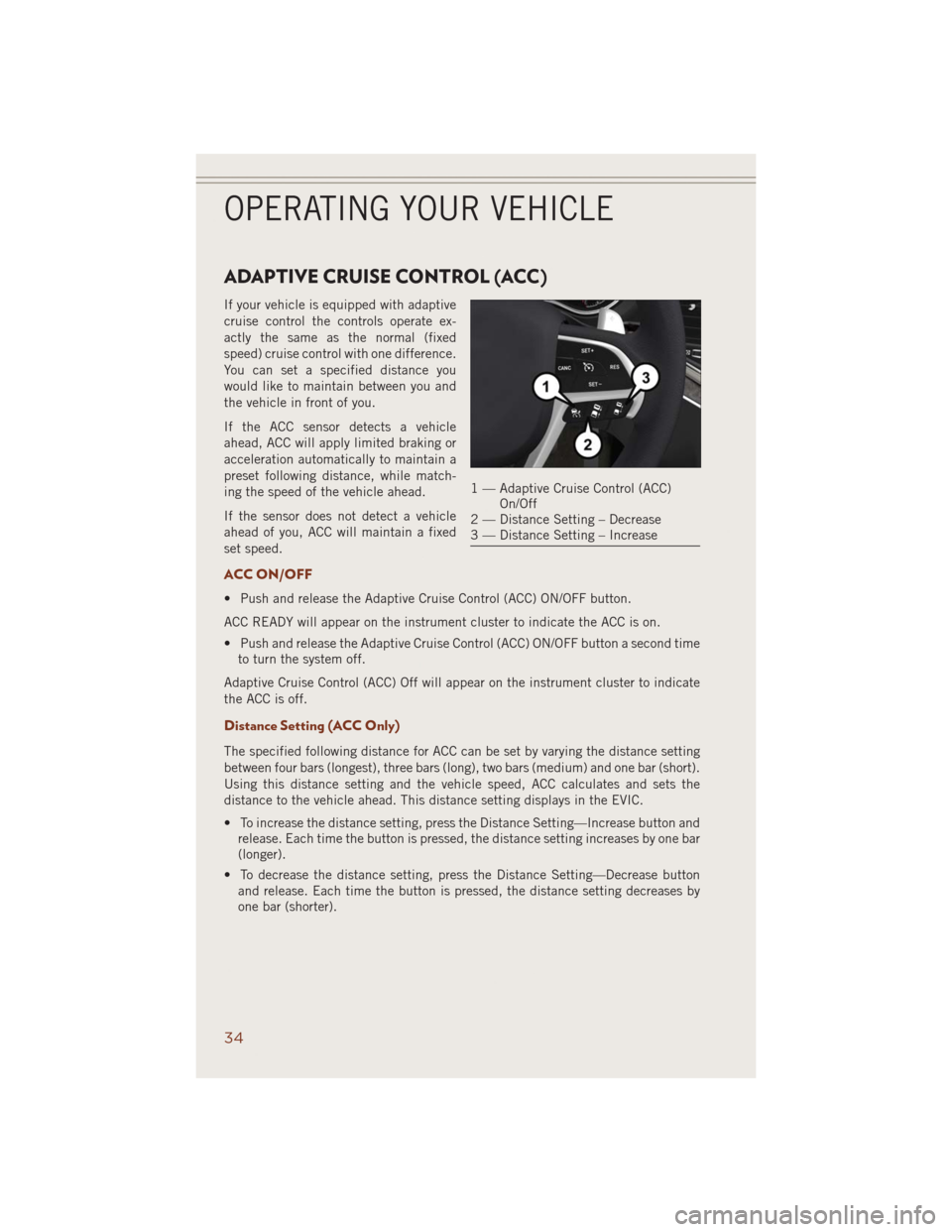
• To increase the distance setting, press the Distance Setting—Increase button and
release. Each time the button is pressed, the distance setting increases by one bar
(longer).
• To decrease the distance setting, press the Distance Setting—Decrease button
and release. Each time the button is pressed, the distance setting decreases by
one bar (shorter).
1 — Adaptive Cruise Control (ACC)
On/Off
2 — Distance Setting – Decrease
3 — Distance Setting – Increase
OPERATING YOUR VEHICLE
34
Page 38 of 220
FORWARD COLLISION WARNING (FCW) WITH
MITIGATION
The Forward Collision Warning (FCW) system with mitigation provides the driver with
audible warnings, visual warnings within the EVIC, and may apply a brake jerk to
warn the driver when it detects a potential frontal collision. The warnings and limited
braking are intended to provide the driver with enough time to react, avoid or mitigate
the potential collision.
NOTE:
FCW monitors the information from the forward looking sensors as well as the
Electronic Brake Controller (EBC), to calculate the probability of a forward collision.
When the system determines that a forward collision is probable, the driver will be
provided with audible and visual warnings and may provide a brake jerk warning.
If the driver does not take action based upon these progressive warnings, then the
system will provide a limited level of active braking to help slow the vehicle and
mitigate the potential forward collision. If the driver reacts to the warnings by braking
and the system determines that the driver intends to avoid the collision by braking
but has not applied sufficient brake force, the system will compensate and provide
additional brake force as required.
Turning FCW ON Or OFF
NOTE:
The default status of FCW is “On”, this allows the system to warn you of a possible
collision with the vehicle in front of you when you are farther away and it applies
limited braking. This gives you the most reaction time to avoid a possible collision.
The forward collision button is on the switch panel that is located in the center of the
instrument panel.
•
To turn the FCW system OFF, press the forward collision button once (LED turns on).
• To turn the FCW system back ON, press the forward collision button again (LED
turns off).
Changing FCW Status
The FCW feature has two settings and can be changed within the Uconnect
®System
Screen:
• Far
• Near
NOTE:
The FCW and active braking settings can only be changed when the vehicle is in
PARK.
OPERATING YOUR VEHICLE
36
Page 44 of 220
SYNC Temperature Soft-Key
• Touch the “SYNC” soft-key on the Uconnect®radio to control the driver and
passenger temperatures simultaneously. Touch the “SYNC” soft-key a second time
to control the temperatures individually.
Air Recirculation
• Use Recirculation for maximum A/C operation.
• For window defogging, turn the recirculation button off.
• If the recirculation button is pushed while in the AUTO mode, the indicator light
may flash three times to indicate the cabin air is being controlled automatically.
Heated Mirrors
The mirrors are heated to melt frost or ice. This feature is activated whenever you turn
on the rear window defroster.
PARKSENSE® FRONT AND REAR PARK ASSIST
ParkSense®can be enabled and disabled by pressing the ParkSense®switch located
below the climate controls, on the switch panel.
The four ParkSense
®sensors, located in the rear fascia/bumper, monitor the area
behind the vehicle that is within the sensors’ field of view. The sensors can detect
obstacles from approximately 12 in (30 cm) up to 79 in (200 cm) from the rear
fascia/bumper in the horizontal direction, depending on the location, type and
orientation of the obstacle.
The six ParkSense
®sensors, located in the front fascia/bumper, monitor the area in
front of the vehicle that is within the sensors’ field of view. The sensors can detect
obstacles from approximately 12 in (30 cm) up to 47 in (120 cm) from the front
fascia/bumper in the horizontal direction, depending on the location, type and
orientation of the obstacle.
When an object is detected within 6.5 ft (2 m) behind the rear bumper while the
vehicle is in REVERSE, a warning will display in the Electronic Vehicle Information
Center (EVIC) and a chime will sound (when Sound and Display is selected from the
Customer Programmable Features section of the Uconnect
®System screen). As the
vehicle moves closer to the object, the chime rate will change from single 1/2 second
tone (for rear only), to slow (for rear only), to fast, to continuous.
Refer to your Owner's Manual on the DVD for further details.
OPERATING YOUR VEHICLE
42
Page 45 of 220
Cleaning The ParkSense® Sensors
If “CLEAN PARK ASSIST SENSORS” appears in the Electronic Vehicle Information
Center (EVIC), clean the ParkSense®sensors with water, car wash soap and a soft
cloth. Do not use rough or hard cloths. Do not scratch or poke the sensors. Otherwise,
you could damage the sensors.
NOTE:
When the Instrument Cluster reads either Clean Sensor or Blinded, please clean off
the bumper sensors to see if the condition is corrected.
PARKVIEW® REAR BACK-UP CAMERA
You can see an on-screen image of the rear of your vehicle whenever the shift lever is
put into REVERSE. The ParkView®Rear Back-Up Camera image will be displayed on
the radio display screen, located on the center stack of the instrument panel.
If the radio display screen appears foggy, clean the camera lens located on the rear
of the vehicle above the rear license plate.
Refer to your Owner's Manual on the DVD for further details.
WARNING!
Drivers must be careful when backing up; even when using the ParkView®Rear
Back-Up Camera. Always check carefully behind your vehicle, and be sure to
check for pedestrians, animals, other vehicles, obstructions, or blind spots before
backing up. You must continue to pay attention while backing up. Failure to do so
can result in serious injury or death.
OPERATING YOUR VEHICLE
43
Page 46 of 220
BLIND SPOT MONITORING
The Blind Spot Monitoring (BSM) system uses two radar-based sensors, located
inside the rear bumper fascia, to detect Highway licensable vehicles (automobiles,
trucks, motorcycles etc.) that enter the blind spot zones from the rear/front/side of
the vehicle.
The Blind Spot Monitoring (BSM) system warning light, located in the outside
mirrors, will illuminate if a vehicle moves into a blind spot zone.
The BSM system can also be configured to sound an audible (chime) alert and mute
the radio to notify you of objects that have entered the detection zones.
Refer to your Owner's Manual on the DVD for further details.
POWER SUNROOF
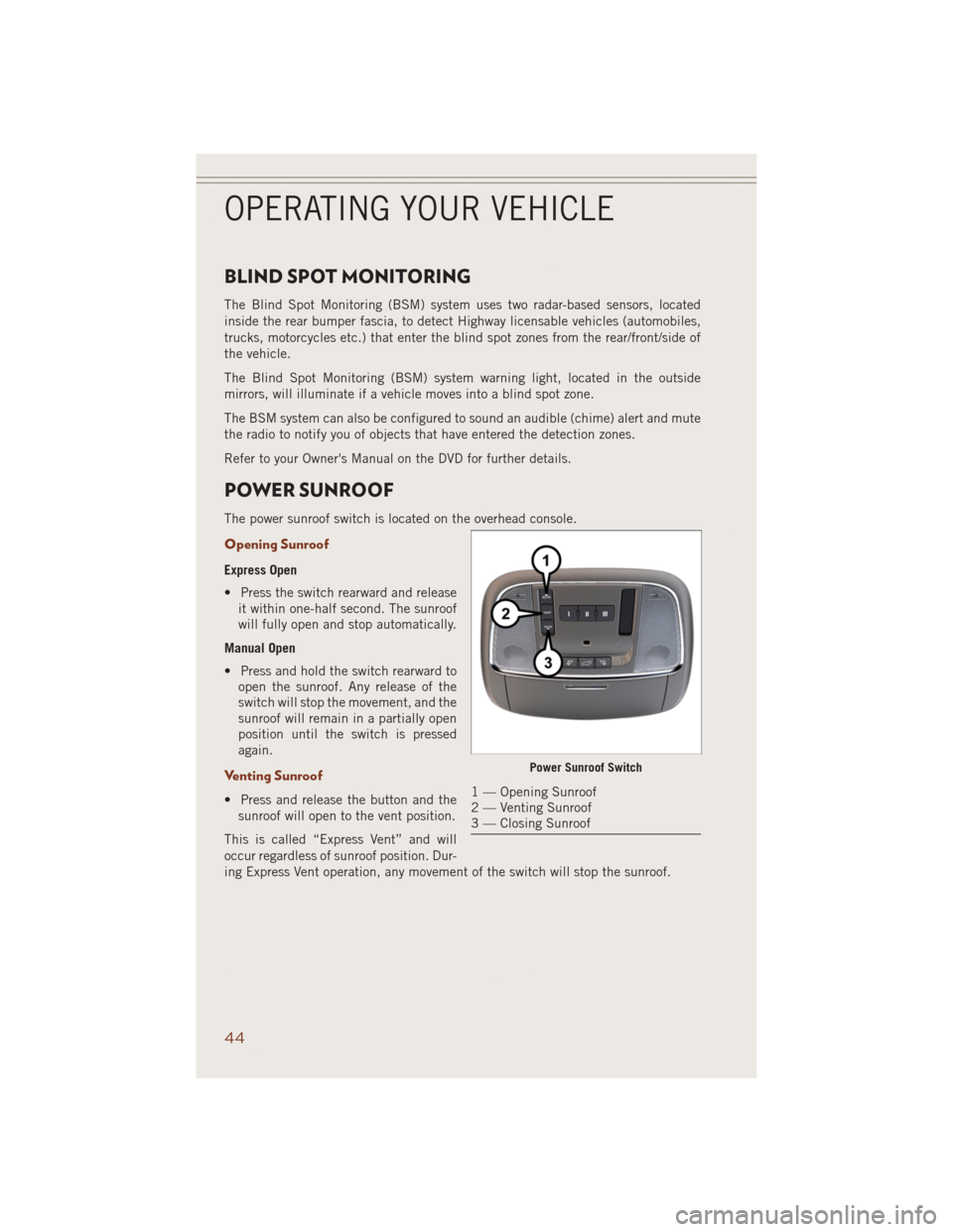
The power sunroof switch is located on the overhead console.
Opening Sunroof
Express Open
• Press the switch rearward and release
it within one-half second. The sunroof
will fully open and stop automatically.
Manual Open
• Press and hold the switch rearward to
open the sunroof. Any release of the
switch will stop the movement, and the
sunroof will remain in a partially open
position until the switch is pressed
again.
Venting Sunroof
• Press and release the button and the
sunroof will open to the vent position.
This is called “Express Vent” and will
occur regardless of sunroof position. Dur-
ing Express Vent operation, any movement of the switch will stop the sunroof.
Power Sunroof Switch
1 — Opening Sunroof
2 — Venting Sunroof
3 — Closing Sunroof
OPERATING YOUR VEHICLE
44
Page 106 of 220
SiriusXM TRAFFIC (US Market Only)
Don't Drive Through Traffic. Drive Around It.
Avoid congestion before you reach it. By enhancing your vehicle's navigation system
with the ability to see detailed traffic information, you can pinpoint traffic incidents,
determine average traffic speed and estimate travel time along your route. Since the
service is integrated with a vehicle's navigation system, SiriusXM Traffic can help
drivers pick the fastest route based on traffic conditions.
1. Detailed information on traffic speed, accidents, construction, and road closings.
2. Traffic information from multiple sources, including police and emergency
services, cameras and road sensors.
3. Coast-to-coast delivery of traffic information.
4. View conditions for points along your route and beyond. Available in over 130
markets.
SiriusXM TRAVEL LINK (US Market Only)
In addition to delivering over 130 channels of the best sports, entertainment, talk,
and commercial-free music, SiriusXM offers premium data services that work in
conjunction with compatible navigation systems. SiriusXM Travel Link brings a
wealth of useful information into your vehicle and right to your fingertips.
•Fuel Prices— Check local gas and diesel prices in your area and route to the
station of your choice.
•Movie Listings— Check local movie theatres and listings in your area and route to
the theater of your choice.
•Sports Scores— In-game and final scores as well as weekly schedules.
•Weather— Check variety of local and national weather information from radar
maps to current and 5-day forecast.
SiriusXM Travel Link feature is completely integrated into your vehicle. A few minutes
after you start your vehicle, Travel Link information arrives and updates in the
background. You can access the information whenever you like, with no waiting.
To access SiriusXM Travel Link, press “Apps” button on the touchscreen, then press
the “SiriusXM Travel Link” button on the touchscreen.
NOTE:
SiriusXM Travel Link requires a subscription, sold separately after the 1 year trial
subscription included with your vehicle purchase.
SiriusXM Travel Link is only available in the United States.
ELECTRONICS
104
Page 146 of 220
DIESEL FUEL FILTERS/WATER SEPARATOR
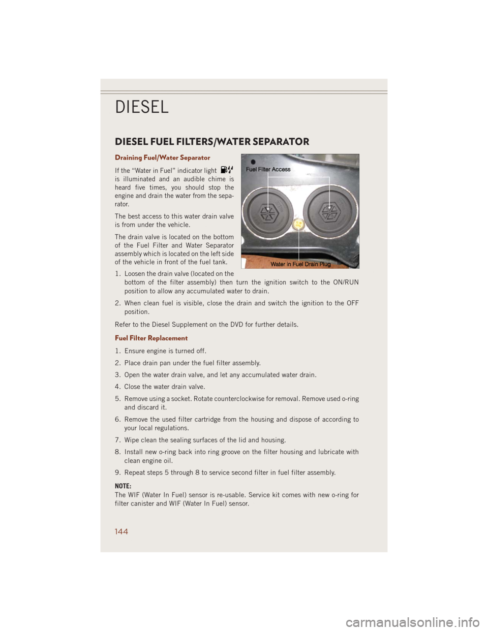
Draining Fuel/Water Separator
If the “Water in Fuel” indicator light
is illuminated and an audible chime is
heard five times, you should stop the
engine and drain the water from the sepa-
rator.
The best access to this water drain valve
is from under the vehicle.
The drain valve is located on the bottom
of the Fuel Filter and Water Separator
assembly which is located on the left side
of the vehicle in front of the fuel tank.
1. Loosen the drain valve (located on the
bottom of the filter assembly) then turn the ignition switch to the ON/RUN
position to allow any accumulated water to drain.
2. When clean fuel is visible, close the drain and switch the ignition to the OFF
position.
Refer to the Diesel Supplement on the DVD for further details.
Fuel Filter Replacement
1. Ensure engine is turned off.
2. Place drain pan under the fuel filter assembly.
3. Open the water drain valve, and let any accumulated water drain.
4. Close the water drain valve.
5. Remove using a socket. Rotate counterclockwise for removal. Remove used o-ring
and discard it.
6. Remove the used filter cartridge from the housing and dispose of according to
your local regulations.
7. Wipe clean the sealing surfaces of the lid and housing.
8. Install new o-ring back into ring groove on the filter housing and lubricate with
clean engine oil.
9. Repeat steps 5 through 8 to service second filter in fuel filter assembly.
NOTE:
The WIF (Water In Fuel) sensor is re-usable. Service kit comes with new o-ring for
filter canister and WIF (Water In Fuel) sensor.
DIESEL
144
Page 149 of 220
System Overview
This vehicle is equipped with a Diesel Exhaust Fluid (DEF) injection system and a
Selective Catalytic Reduction (SCR) catalyst to meet the emission requirements.
The DEF injection system consists of the following components:
• DEF tank
• DEF pump
• DEF injector
• Electronically-heated DEF lines• NOx sensors
• Temperature sensors
• SCR catalyst
The DEF injection system and SCR catalyst enable the achievement of diesel
emissions requirements; while maintaining outstanding fuel economy, drivability,
torque and power ratings.
NOTE:
• Your vehicle is equipped with a DEF injection system. You may occasionally hear
an audible clicking noise. This is normal operation.
• The DEF pump will run for a period of time after engine shutdown to purge the DEF
system. This is normal operation.
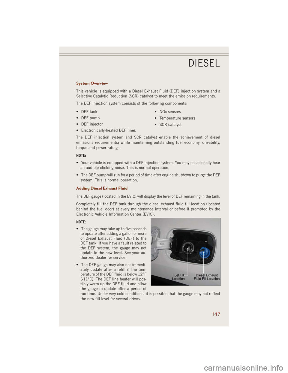
Adding Diesel Exhaust Fluid
The DEF gauge (located in the EVIC) will display the level of DEF remaining in the tank.
Completely fill the DEF tank through the diesel exhaust fluid fill location (located
behind the fuel door) at every maintenance interval or before if prompted by the
Electronic Vehicle Information Center (EVIC).
NOTE:
• The gauge may take up to five seconds
to update after adding a gallon or more
of Diesel Exhaust Fluid (DEF) to the
DEF tank. If you have a fault related to
the DEF system, the gauge may not
update to the new level. See your au-
thorized dealer for service.
• The DEF gauge may also not immedi-
ately update after a refill if the tem-
perature of the DEF fluid is below 12°F
(-11°C). The DEF line heater will pos-
sibly warm up the DEF fluid and allow
the gauge to update after a period of
run time. Under very cold conditions, it is possible that the gauge may not reflect
the new fill level for several drives.
DIESEL
147
Page 153 of 220
Please note that the TPMS is not a substitute for proper tire maintenance, and it is
the driver’s responsibility to maintain correct tire pressure, even if under-inflation
has not reached the level to trigger illumination of the TPMS low EVIC display.
Your vehicle has also been equipped with a TPMS malfunction indicator to indicate
when the system is not operating properly. The TPMS malfunction indicator is
combined with the low tire pressure telltale. When the system detects a malfunction,
the telltale will flash for approximately one minute and then remain continuously
illuminated. This sequence will continue each time the vehicle is restarted as long as
the malfunction exists.
When the malfunction indicator is illuminated, the system may not be able to detect
or signal low tire pressure as intended. TPMS malfunctions may occur for a variety of
reasons, including the installation of replacement or alternate tires or wheels on the
vehicle that prevent the TPMS from functioning properly. Always check the TPMS
malfunction telltale after replacing one or more tires or wheels on your vehicle, to
ensure that the replacement or alternate tires and wheels allow the TPMS to continue
to function properly.
NOTE:
Tire pressures change by approximately 1 psi (7 kPa) per 12° F (7° C) of air
temperature change. Keep this in mind when checking tire pressure inside a garage,
especially in the Winter. Example: If garage temperature is 68°F (20°C) and the
outside temperature is 32°F (0°C), then the cold tire inflation pressure should be
increased by 3 psi (21 kPa), which equals 1 psi (7 kPa) for every 12°F (7°C) for this
outside temperature condition.
CAUTION!
The TPMS has been optimized for the original equipment tires and wheels. TPMS
pressures and warning have been established for the tire size equipped on your
vehicle. Undesirable system operation or sensor damage may result when using
replacement equipment that is not of the same size, type, and/or style. Aftermar-
ket wheels can cause sensor damage. Do not use tire sealant from a can, or
balance beads if your vehicle is equipped with a TPMS, as damage to the sensors
may result.
- Seat Belt Reminder Light
When the ignition switch is first turned to the ON/RUN position, this light will turn on
for four to eight seconds as a bulb check. During the bulb check, if the driver's seat
belt is unbuckled, a chime will sound. After the bulb check or when driving, if the
driver or front passenger seat belt remains unbuckled, the Seat Belt Indicator Light
will flash or remain on continuously. Refer to “Seat Belts” in “Getting Started” of this
user guide for further information.
WHAT TO DO IN EMERGENCIES
151
Page 203 of 220
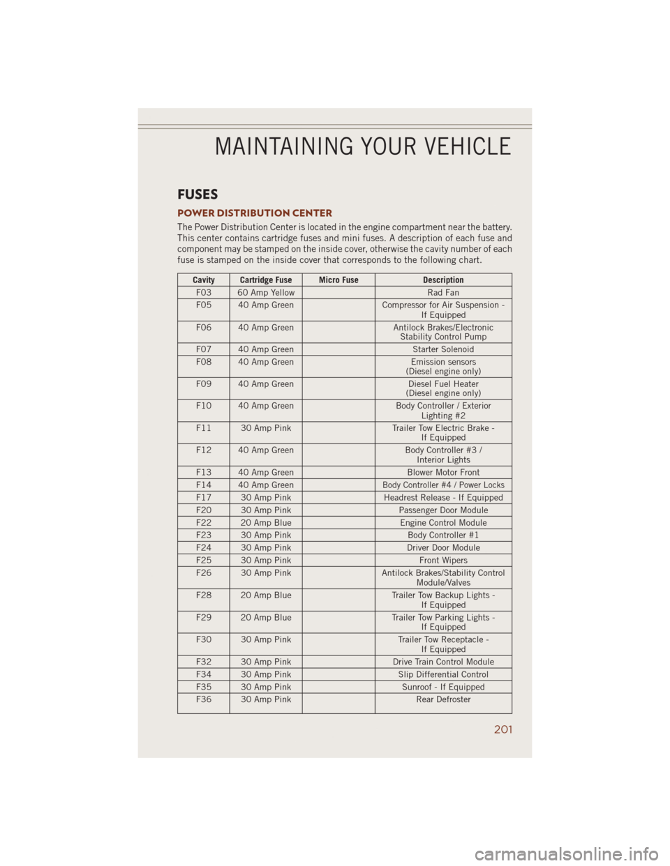
FUSES
POWER DISTRIBUTION CENTER
The Power Distribution Center is located in the engine compartment near the battery.
This center contains cartridge fuses and mini fuses. A description of each fuse and
component may be stamped on the inside cover, otherwise the cavity number of each
fuse is stamped on the inside cover that corresponds to the following chart.
Cavity Cartridge Fuse Micro Fuse Description
F03 60 Amp Yellow Rad Fan
F05 40 Amp Green Compressor for Air Suspension -
If Equipped
F06 40 Amp Green Antilock Brakes/Electronic
Stability Control Pump
F07 40 Amp Green Starter Solenoid
F08 40 Amp Green Emission sensors
(Diesel engine only)
F09 40 Amp Green Diesel Fuel Heater
(Diesel engine only)
F10 40 Amp Green Body Controller / Exterior
Lighting #2
F11 30 Amp Pink Trailer Tow Electric Brake -
If Equipped
F12 40 Amp Green Body Controller #3 /
Interior Lights
F13 40 Amp Green Blower Motor Front
F14 40 Amp Green
Body Controller #4 / Power Locks
F17 30 Amp Pink Headrest Release - If Equipped
F20 30 Amp Pink Passenger Door Module
F22 20 Amp Blue Engine Control Module
F23 30 Amp Pink Body Controller #1
F24 30 Amp Pink Driver Door Module
F25 30 Amp Pink Front Wipers
F26 30 Amp Pink Antilock Brakes/Stability Control
Module/Valves
F28 20 Amp Blue Trailer Tow Backup Lights -
If Equipped
F29 20 Amp Blue Trailer Tow Parking Lights -
If Equipped
F30 30 Amp Pink Trailer Tow Receptacle -
If Equipped
F32 30 Amp Pink Drive Train Control Module
F34 30 Amp Pink Slip Differential Control
F35 30 Amp Pink Sunroof - If Equipped
F36 30 Amp Pink Rear Defroster
MAINTAINING YOUR VEHICLE
201