lock JEEP GRAND CHEROKEE 2016 WK2 / 4.G Service Manual
[x] Cancel search | Manufacturer: JEEP, Model Year: 2016, Model line: GRAND CHEROKEE, Model: JEEP GRAND CHEROKEE 2016 WK2 / 4.GPages: 276, PDF Size: 10.84 MB
Page 168 of 276
2. Pull the bottom of the cover outward (towards you).
3. Lower back down to disengage the tabs located at the top of the hitch receivercover and then pull outwards to remove.
To reinstall the hitch receiver cover after
towing repeat the procedure in reverse
order.
NOTE:
Be sure to engage all tabs of the hitch
receiver cover in the bumper fascia prior
to installation.
Hitch Receiver Cover
Hitch Receiver Cover
1 — Hitch Receiver Cover Retaining
Tabs
2 — Hitch Receiver Cover
3 — Locking Retainer
UTILITY
166
Page 183 of 276
CAUTION!
If the “Water in Fuel Indicator Light” remains on, DO NOT START the engine
before you drain the water from the fuel filters to avoid engine damage. Refer to
“Maintenance Procedures/Draining Fuel/Water Separator Filter” in “Maintaining
Your Vehicle” in your Diesel Supplement on the DVD for further information.
Extreme Cold Weather
The engine block heater is a resistance heater installed in the water jacket of the
engine. It requires a 110–115 Volt AC electrical outlet with a grounded, three-wire
extension cord.
Its use is recommended for environments that routinely fall below -10°F. It should be
used when the vehicle has not been running overnight or longer periods and should
be plugged in two hours prior to start. Its use is required for cold starts with
temperatures under -20°F.
A 12 Volt heater built into the fuel filter housing aids in preventing fuel gelling. It is
controlled by a built-in thermostat.
A Diesel Pre-Heat system both improves engine starting and reduces the amount of
white smoke generated by a warming engine.
NOTE:
The engine block heater cord is a factory installed option. If your vehicle is not
equipped, heater cords are available from your authorized MOPAR dealer.
Water In Fuel Message
If a Water In Fuel message orindicator appears in the cluster and a chime
sounds five times, the fuel/water separator will need to be drained immediately to
prevent engine damage.
Refer to “Draining Fuel Water Separator” in this guide for draining instructions or see
your dealer.
DIESEL
181
Page 184 of 276
DIESEL FUEL FILTERS/WATER SEPARATOR
Draining Fuel/Water Separator
If the “Water in Fuel” indicator light
is illuminated and an audible chime
is heard five times, you should stop the
engine and drain the water from the sepa-
rator.
The best access to this water drain valve
is from under the vehicle.
The drain valve is located on the bottom
of the Fuel Filter and Water Separator
assembly which is located on the left side
of the vehicle in front of the fuel tank.
1. Loosen the drain valve (located on the bottom of the filter assembly) then
turn the ignition switch to the ON/
RUN position to allow any accumu-
lated water to drain.
2. When clean fuel is visible, close the drain and switch the ignition to the OFF position.
Refer to the Diesel Supplement on the DVD for further details.
Fuel Filter Replacement
1. Ensure engine is turned off.
2. Place drain pan under the fuel filter assembly.
3. Open the water drain valve, and let any accumulated water drain.
4. Close the water drain valve.
5. Remove using a socket. Rotate counterclockwise for removal.
6. Remove the used filter cartridge from the housing and dispose of according to your local regulations.
7. Wipe clean the sealing surfaces of the lid and housing.
8. Lubricate o-ring on new filter with clean engine oil.
9. Repeat steps 5 through 8 to service second filter in fuel filter assembly.
Fuel Filter And Water Separator Assembly
1 — Fuel Filter Access
2 — Water In Fuel Drain
DIESEL
182
Page 192 of 276
– Transmission Temperature Warning Light
This light indicates that there is excessive transmission fluid temperature that might
occur with severe usage such as trailer towing. If this light turns on, stop the vehicle
and run the engine at idle, with the transmission in NEUTRAL, until the light turns
off. Once the light turns off, you may continue to drive normally.
CAUTION!
Continuous driving with the Transmission Temperature Warning Light illuminated
will eventually cause severe transmission damage or transmission failure.
WARNING!
If you continue operating the vehicle when the Transmission Temperature Warning
Light is illuminated you could cause the fluid to boil over, come in contact with hot
engine or exhaust components and cause a fire.
– Anti-Lock Brake (ABS) Light
This light monitors the Anti-Lock Brake System (ABS). The light will turn on when the
ignition switch is turned to the ON/RUN position and may stay on for as long as four
seconds.
If the ABS light remains on or turns on while driving, it indicates that the Anti-Lock
portion of the brake system is not functioning and that service is required. However,
the conventional brake system will continue to operate normally if the BRAKE
warning light is not on.
If the ABS light is on, the brake system should be serviced as soon as possible to
restore the benefits of Anti-Lock brakes. If the ABS light does not turn on when the
ignition switch is turned to the ON/RUN position, have the light inspected by an
authorized dealer.
– Air Bag Warning Light
This light will turn on for four to eight seconds as a bulb check when the ignition
switch is first turned to the ON/RUN position. If the light is either not on during
starting, stays on, or turns on while driving, have the system inspected at an
authorized dealer as soon as possible. Refer to “Occupant Restraints” in “Things To
Know Before Starting Your Vehicle” in your Owner’s Manual on the DVD for further
information.
NOTE:
The Air Bag System is designed to be maintenance free.
WHAT TO DO IN EMERGENCIES
190
Page 195 of 276
– Brake Warning Light
This light monitors various brake functions, including brake fluid level and parking
brake application. If the brake light turns on, it may indicate that the parking brake
is applied, that the brake fluid level is low, or that there is a problem with the brake
system master cylinder reservoir.
If the light remains on when the parking brake has been disengaged, and the fluid
level is at the full mark on the master cylinder reservoir, it indicates a possible brake
hydraulic system malfunction or that a problem with the Brake Booster has been
detected by the Anti-Lock Brake System (ABS)/Electronic Stability Control (ESC)
system. In this case, the light will remain on until the condition has been corrected.
If the problem is related to the brake booster, the ABS pump will run when applying
the brake, and a brake pedal pulsation may be felt during each stop.
The dual brake system provides a reserve braking capacity in the event of a failure to
a portion of the hydraulic system. A leak in either half of the dual brake system is
indicated by the Brake Warning Light, which will turn on when the brake fluid level
in the master cylinder has dropped below a specified level. The light will remain on
until the cause is corrected.
Vehicles equipped with the Anti-Lock Brake System (ABS) are also equipped with
Electronic Brake Force Distribution (EBD). In the event of an EBD failure, the Brake
Warning Light will turn on along with the ABS Light. Immediate repair to the ABS
system is required.
Operation of the Brake Warning Light can be checked by turning the ignition switch
from the OFF position to the ON/RUN position. The light should illuminate for
approximately two seconds. The light should then turn off unless the parking brake
is applied or a brake fault is detected. If the light does not illuminate, have the light
inspected by an authorized dealer.
The light also will turn on when the parking brake is applied with the ignition switch
in the ON/RUN position.
NOTE:
This light shows only that the parking brake is applied. It does not show the degree
of brake application.
WARNING!
Driving a vehicle with the red brake light on is dangerous. Part of the brake system
may have failed. It will take longer to stop the vehicle. You could have a collision.
Have the vehicle checked immediately.
WHAT TO DO IN EMERGENCIES
193
Page 198 of 276
– Door Open Indicator
This indicator will illuminate when a door(s) is left open and not fully closed.
– Electronic Stability Control (ESC) OFF Indicator Light
This light indicates the Electronic Stability Control (ESC) is off.
– Windshield Washer Fluid Low Indicator
This indicator will illuminate when the windshield washer fluid is low.
– Hood Open Indicator
This indicator will illuminate when the hood is left open and not fully closed.
– Liftgate Ajar Indicator — If Equipped
This indicator will illuminate when the liftgate is left ajar and not fully closed.
Engine Oil Life Reset
Oil Change Required
Your vehicle is equipped with an engine oil change indicator system. The “Oil Change
Required” message will display in the DID for five seconds after a single chime has
sounded, to indicate the next scheduled oil change interval. The engine oil change
indicator system is duty cycle based, which means the engine oil change interval may
fluctuate, dependent upon your personal driving style.
Unless reset, this message will continue to display each time you turn the ignition
switch to the ON/RUN position or cycle the ignition to the ON/RUN position if
equipped with Keyless Enter-N-Go. To turn off the message temporarily, push and
release the OK button. To reset the oil change indicator system (after performing the
scheduled maintenance) refer to the following procedure.
Vehicles Equipped With Keyless Enter-N-Go
1. Without pushing the brake pedal, push the ENGINE START/STOP button andplace the ignition to the ON/RUN position (do not start the engine.)
2. Fully depress the accelerator pedal, slowly, three times within 10 seconds.
3. Without pushing the brake pedal, push the ENGINE START/STOP button once to return the ignition to the OFF/LOCK position.
NOTE:
If the indicator message illuminates when you start the vehicle, the oil change
indicator system did not reset. If necessary, repeat this procedure.
NOTE:
It can also be reset using the Oil Life menu in Vehicle Info.
WHAT TO DO IN EMERGENCIES
196
Page 202 of 276
Preparations For Jacking
CAUTION!
Always lift or jack the vehicle from the correct jacking points. Failure to follow this
information could cause damage to the vehicle or underbody components.
NOTE:
To assist with changing a spare tire, the air suspension system (if equipped) has a
feature which allows the automatic leveling to be disabled.
1. Park the vehicle on a firm, level surface. Avoid ice or slippery surfaces.
WARNING!
Do not attempt to change a tire on the side of the vehicle closest to moving traffic,
pull far enough off the road to avoid being hit when operating the jack or changing
the wheel.
2. Turn on the Hazard Warning flasher.
3. Set the parking brake.
4. Place the gear selector into PARK.
5. Turn the ignition OFF.
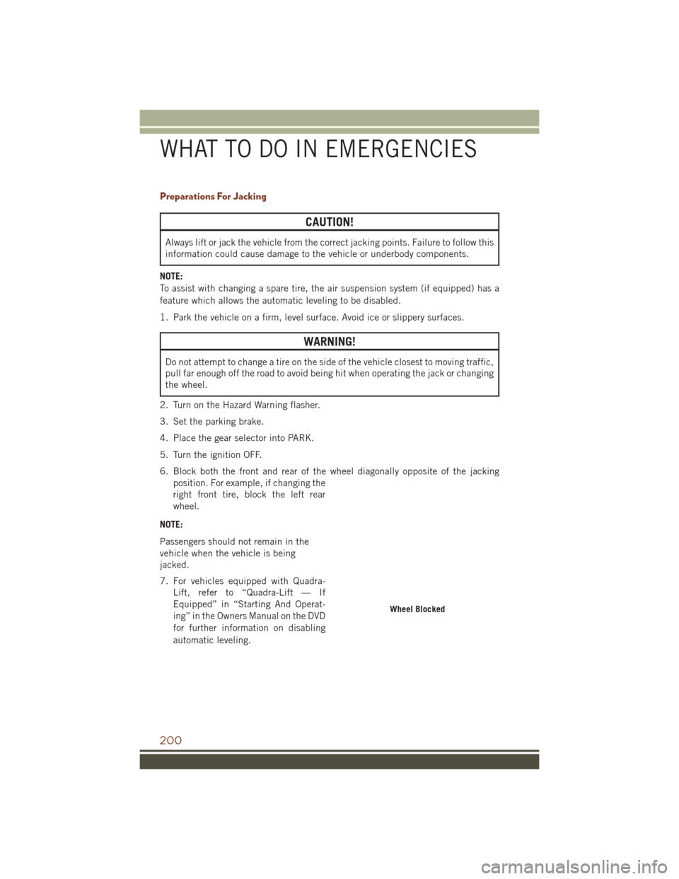
6. Block both the front and rear of the wheel diagonally opposite of the jacking position. For example, if changing the
right front tire, block the left rear
wheel.
NOTE:
Passengers should not remain in the
vehicle when the vehicle is being
jacked.
7. For vehicles equipped with Quadra- Lift, refer to “Quadra-Lift — If
Equipped” in “Starting And Operat-
ing” in the Owners Manual on the DVD
for further information on disabling
automatic leveling.
Wheel Blocked
WHAT TO DO IN EMERGENCIES
200
Page 205 of 276
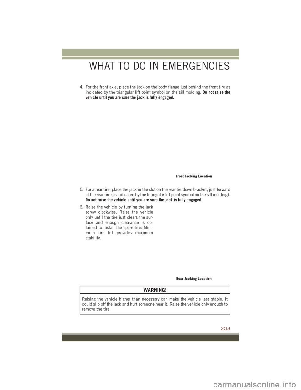
4. For the front axle, place the jack on the body flange just behind the front tire asindicated by the triangular lift point symbol on the sill molding. Do not raise the
vehicle until you are sure the jack is fully engaged.
5. For a rear tire, place the jack in the slot on the rear tie-down bracket, just forward of the rear tire (as indicated by the triangular lift point symbol on the sill molding).
Do not raise the vehicle until you are sure the jack is fully engaged.
6. Raise the vehicle by turning the jack screw clockwise. Raise the vehicle
only until the tire just clears the sur-
face and enough clearance is ob-
tained to install the spare tire. Mini-
mum tire lift provides maximum
stability.
WARNING!
Raising the vehicle higher than necessary can make the vehicle less stable. It
could slip off the jack and hurt someone near it. Raise the vehicle only enough to
remove the tire.
Front Jacking Location
Rear Jacking Location
WHAT TO DO IN EMERGENCIES
203
Page 206 of 276
7. Remove the lug nuts and wheel.
8. Position the spare wheel/tire on the vehicle and install the lug nuts with thecone-shaped end toward the wheel. Lightly tighten the nuts.
CAUTION!
Be sure to mount the spare tire with the valve stem facing outward. The vehicle
could be damaged if the spare tire is mounted incorrectly.
WARNING!
To avoid the risk of forcing the vehicle off the jack, do not tighten the lug nuts fully
until the vehicle has been lowered. Failure to follow this warning may result in
serious injury.
9. Lower the vehicle by turning the jack screw counterclockwise, and remove the jack and wheel blocks.
10. Finish tightening the lug nuts. Push down on the wrench while at the end of the handle for increased leverage. Tighten the lug nuts in a star pattern until each
nut has been tightened twice. The correct tightness of each lug nut is 130 ft-lbs
(176 N·m). If in doubt about the correct tightness, have them checked with a
torque wrench by your authorized dealer or service station.
NOTE:
For the SRT model the correct wheel nut tightness is 110 ft lbs (149 N·m).
11. Lower the jack to the fully closed position and return it and the tools to the proper positions in the foam tray.
Installing Spare Wheel/Tire
WHAT TO DO IN EMERGENCIES
204
Page 207 of 276
12. Remove the small center cap and securely store the road wheel in the cargo area.
13. Have the aluminum road wheel andtire repaired as soon as possible,
properly secure the spare tire with
the special wing nut torqued to
3.7 ft-lbs (5 N·m), reinstall the jack
and tool kit foam tray, and latch the
rear load floor cover.
NOTE:
Do not drive with the spare tire installed
for more than 50 miles (80 km) at a max
speed of 50 mph (80 km/h).
WARNING!
A loose tire or jack thrown forward in a collision or hard stop could endanger the
occupants of the vehicle. Always stow the jack parts and the spare tire in the
places provided. Have the deflated (flat) tire repaired or replaced immediately.
Road Tire Installation
1. Mount the road tire on the axle.
2. Install the remaining lug nuts with the cone shaped end of the nut toward the wheel. Lightly tighten the lug nuts.
WARNING!
To avoid the risk of forcing the vehicle off the jack, do not tighten the lug nuts fully
until the vehicle has been lowered. Failure to follow this warning may result in
personal injury.
3. Lower the vehicle to the ground by turning the jack handle counterclockwise.
4. Finish tightening the lug nuts. Push down on the wrench while at the end of the handle for increased leverage. Tighten the lug nuts in a star pattern until each nut
has been tightened twice. The correct tightness of each lug nut is 130 ft-lbs
(176 N·m). If in doubt about the correct tightness, have them checked with a
torque wrench by your authorized dealer or service station.
NOTE:
For the SRT model the correct wheel nut tightness is 110 ft lbs (149 N·m).
5. After 25 miles (40 km) check the lug nut torque with a torque wrench to ensure that all lug nuts are properly seated against the wheel.
Spare Tire
WHAT TO DO IN EMERGENCIES
205