automatic transmission JEEP GRAND CHEROKEE 2017 WK2 / 4.G Owner's Manual
[x] Cancel search | Manufacturer: JEEP, Model Year: 2017, Model line: GRAND CHEROKEE, Model: JEEP GRAND CHEROKEE 2017 WK2 / 4.GPages: 372
Page 162 of 372
AutoStick
AutoStick is a driver-interactive transmission
feature providing manual shift control, giving
you more control of the vehicle. AutoStick
allows you to maximize engine braking, elimi-
nate undesirable upshifts and downshifts,
and improve overall vehicle performance.
This system can also provide you with more
control during passing, city driving, cold slip-
pery conditions, mountain driving, trailer
towing, and many other situations.
Operation
To activate AutoStick mode, move the gear
selector into the MANUAL (M) position (be-
side the DRIVE position), or tap one of the
shift paddles on the steering wheel. Tapping
the (-) shift paddle to enter AutoStick mode
will downshift the transmission to the nextlower gear, while tapping (+) to enter
AutoStick mode will retain the current gear.
The current transmission gear will be dis-
played in the instrument cluster. In AutoStick
mode, you can use the gear selector (in the
MANUAL position), or the shift paddles, to
manually shift the transmission. Tapping the
gear selector forward (-) while in the
MANUAL (M) position, or tapping the (-) shift
paddle on the steering wheel, will downshift
the transmission to the next lower gear. Tap-
ping the lever rearward (+) (or tapping the (+)
shift paddle) will command an upshift.
NOTE:
The shift paddles may be disabled (or re-
enabled, as desired) using the Uconnect Per-
sonal Settings or, in SRT models, using Drive
Modes.
In AutoStick mode, the transmission will
shift up or down when (+/-) is manually se-
lected by the driver (using the gear selector,
or the shift paddles), unless an engine lug-
ging or overspeed condition would result. It
will remain in the selected gear until another
upshift or downshift is chosen, except as
described below. • The transmission will automatically down-
shift as the vehicle slows (to prevent en-
gine lugging) and will display the current
gear.
• The transmission will automatically down- shift to first gear when coming to a stop.
After a stop, the driver should manually
upshift (+) the transmission as the vehicle
is accelerated.
• You can start out, from a stop, in first or second gear (or third gear, in 4LO range,
Snow mode, or Sand mode). Tapping (+)
(at a stop) will allow starting in second
gear. Starting out in second gear can be
helpful in snowy or icy conditions.
• If a requested downshift would cause the engine to over-speed, that shift will not
occur.
• The system will ignore attempts to upshift at too low of a vehicle speed.
• Holding the (-) paddle depressed, or hold- ing the gear selector in the (-) position, will
downshift the transmission to the lowest
gear possible at the current speed.
• Transmission shifting will be more notice- able when AutoStick is enabled.
Shift Paddles
STARTING AND OPERATING
160
Page 163 of 372
• The system may revert to automatic shiftmode if a fault or overheat condition is
detected.
NOTE:
When Selec-Speed or Hill Descent Control is
enabled, AutoStick is not active.
To disengage AutoStick, return the gear se-
lector to the DRIVE position, or press and
hold the (+) shift paddle (if the gear selector
is already in DRIVE) until "D" is once again
indicated in the instrument cluster. You can
shift in or out of AutoStick at any time with-
out taking your foot off the accelerator pedal.
WARNING!
Do not downshift for additional engine
braking on a slippery surface. The drive
wheels could lose their grip and the ve-
hicle could skid, causing a collision or
personal injury.
SPORT MODE — IF
EQUIPPED
Your vehicle is equipped with a Sport Mode
feature. This mode is a configuration set up
for typical enthusiast driving. The engine,
transmission, and steering systems are all set
to their SPORT settings. Sport Mode will
provide improved throttle response and modi-
fied shifting for an enhanced driving experi-
ence, as well the greatest amount of steering feel. This mode may be activated and deac-
tivated by pushing the Sport button on the
instrument panel switch bank.
FOUR WHEEL DRIVE
OPERATION
Quadra-Trac I Operating Instructions/
Precautions — If Equipped
The Quadra-Trac I is a single-speed (HI range
only) transfer case, which provides conve-
nient full-time four-wheel drive. No driver
interaction is required. The Brake Traction
Control (BTC) System, which combines stan-
dard ABS and Traction Control, provides re-
sistance to any wheel that is slipping to allow
additional torque transfer to wheels with trac-
tion.
NOTE:
The Quadra-Trac I system is not appropriate
for conditions where 4WD LOW range is rec-
ommended. Refer to “Off-Road Driving Tips”
in “Starting And Operating” for further infor-
mation.
Sport Mode Button
161
Page 167 of 372
8. Release the brake pedal for five secondsand ensure that there is no vehicle
movement.
NOTE:
If shift conditions/interlocks are not met, a
“To Tow Vehicle Safely, Read Neutral Shift
Procedure in Owner’s Manual” message will
flash from the instrument cluster display.
Refer to “Instrument Cluster Display” in
“Getting To Know Your Instrument Panel” for
further information.
Shifting Out Of NEUTRAL (N)
Use the following procedure to prepare your
vehicle for normal usage.
1. Bring the vehicle to a complete stop.
2. Firmly apply the parking brake.
3. Start the engine.
4. Press and hold the brake pedal.
5. Shift the transmission into NEUTRAL. 6. Using a ballpoint pen or similar object,
push and hold the recessed transfer case
NEUTRAL (N) button (located by the se-
lector switch) for one second.
7. When the NEUTRAL (N) indicator light turns off, release the NEUTRAL (N)
button.
8. After the NEUTRAL (N) button has been released, the transfer case will shift to the
position indicated by the selector switch.
Quadra-Drive II System — If Equipped
The optional Quadra-Drive II System features
two torque transfer couplings. The couplings
include an Electronic Limited-Slip Differen-
tial (ELSD) rear axle and the Quadra-Trac II
transfer case. The optional ELSD axle is fully
automatic and requires no driver input to
operate. Under normal driving conditions,
the unit functions as a standard axle, balanc-
ing torque evenly between left and right
wheels. With a traction difference between
left and right wheels, the coupling will sense
a speed difference. As one wheel begins to
spin faster than the other, torque will auto-
matically transfer from the wheel that has
less traction, to the wheel that has traction.
While the transfer case and axle coupling
differ in design, their operation is similar.
Follow the Quadra-Trac II transfer case shift-
ing information, preceding this section, for
shifting this system.
NEUTRAL (N) Switch
165
Page 173 of 372
NOTE:
Activate the Hill Descent Control or Selec
Speed Control for steep downhill control. See
“Electronic Brake Control System” in this
section for further information.
Instrument Cluster Display Messages
When the appropriate conditions exist, a
message will appear in the instrument clus-
ter. Refer to “Instrument Cluster Display” in
“Getting To Know Your Instrument Panel” for
further information.
SELEC-TRACK — IF
EQUIPPED (SRT)
Description
Selec-Track combines the capabilities of the
vehicle control systems, along with driver
input, to provide the best performance for all
terrains.
Rotate the Selec-Track knob to select the
desired mode.Refer to “Drive Modes” in the “Multimedia”
section in your Owner’s Manual at
www.jeep.com/en/owners/manuals/ for fur-
ther information.
Selec-Track consists of the following posi-
tions:
•
Sport – Dry weather, on-road calibration.
Performance based tuning that provides a
rear wheel drive feel but with improved
handling and acceleration over a two-
wheel drive vehicle. This feature will reset
to AUTO on an ignition cycle.
• Snow – Tuning set for additional stability in
inclement weather. Use on and off road on
loose traction surfaces such as snow. This
feature will reset to AUTO upon an ignition
cycle. •
Auto – Fully automatic full time four-wheel
drive operation can be used on and off
road. Balances traction with seamless
steering feel to provide improved handling
and acceleration over two-wheel drive ve-
hicles.
• Track – Track road calibration for use on
high traction surfaces. Driveline is maxi-
mized for traction. Some binding may be
felt on less forgiving surfaces. This feature
will reset to AUTO on an ignition cycle.
• To w – Use this mode for towing and haul-
ing heavy loads. Vehicle suspension will go
to sport mode. Trailer sway control is en-
abled in the ESC system. This feature will
reset to AUTO upon an ignition cycle.
Custom
This mode allows the driver to create a cus-
tom vehicle configuration that is saved for
quick selection of favorite settings. The sys-
tem will return to AUTO mode when the
ignition switch is cycled from RUN to OFF to
RUN, if this mode is selected. While in Cus-
tom Mode the Stability, Transmission, Steer-
Selec-Track Switch
171
Page 183 of 372
79 inches (200 cm) from the rear fascia/
bumper in the horizontal direction, depend-
ing on the location, type and orientation of
the obstacle.
The six ParkSense sensors, located in the
front fascia/bumper, monitor the area in front
of the vehicle that is within the sensors’ field
of view. The sensors can detect obstacles
from approximately 12 inches (30 cm) up to
47 inches (120 cm) from the front fascia/
bumper in the horizontal direction, depend-
ing on the location, type and orientation of
the obstacle.
When an object is detected within 79 inches
(200 cm) behind the rear bumper while the
vehicle is in REVERSE, a warning will appear
in the instrument cluster display. In addition
a chime will sound (when Sound and Display
is selected from the Customer Programmable
Features section of the Uconnect System
screen). As the vehicle moves closer to the
object, the chime rate will change from single
1/2 second tone (for rear only), to slow (for
rear only), to fast, to continuous.Activation/Deactivation
The ParkSense Park Assist system provides
visual and audible indications of the distance
between the rear and/or front fascia and a
detected obstacle when backing up or moving
forward, e.g. during a parking maneuver. If
your vehicle is equipped with an Automatic
Transmission, the vehicle brakes may be au-
tomatically applied and released when per-
forming a reverse parking maneuver if the
system detects a possible collision with an
obstacle.
ParkSense can be active only when the gear
selector is in REVERSE or DRIVE. If
ParkSense is enabled at one of these gear
selector positions, the system will remain
active until the vehicle speed is increased to
approximately 7 mph (11 km/h) or above. A
display warning will appear in the instrument
cluster display indicating the vehicle is above
ParkSense operating speed. The system will
become active again if the vehicle speed is
decreased to speeds less than approximately
6 mph (9 km/h).
Engagement/Disengagement
To disengage the system, push the ParkSense
switch, located on the switch panel below the
Uconnect display.
When the system passes from engaged to
disengaged and vice versa, it is always ac-
companied by a dedicated message in the
instrument cluster display.
System engaged:ParkSense switch LED off.
System disengaged: ParkSense switch LED on
constantly.
The ParkSense switch LED lights up also in
the case of a ParkSense system failure. If the
button is pushed with a system failure, the
ParkSense switch LED flashes for about
5 seconds, then it stays on constantly.
After the ParkSense has been disengaged, it
will stay in this condition until the following
engagement, even if the ignition device
passes from ON/RUN to OFF and then again
to ON/RUN.
181
Page 197 of 372
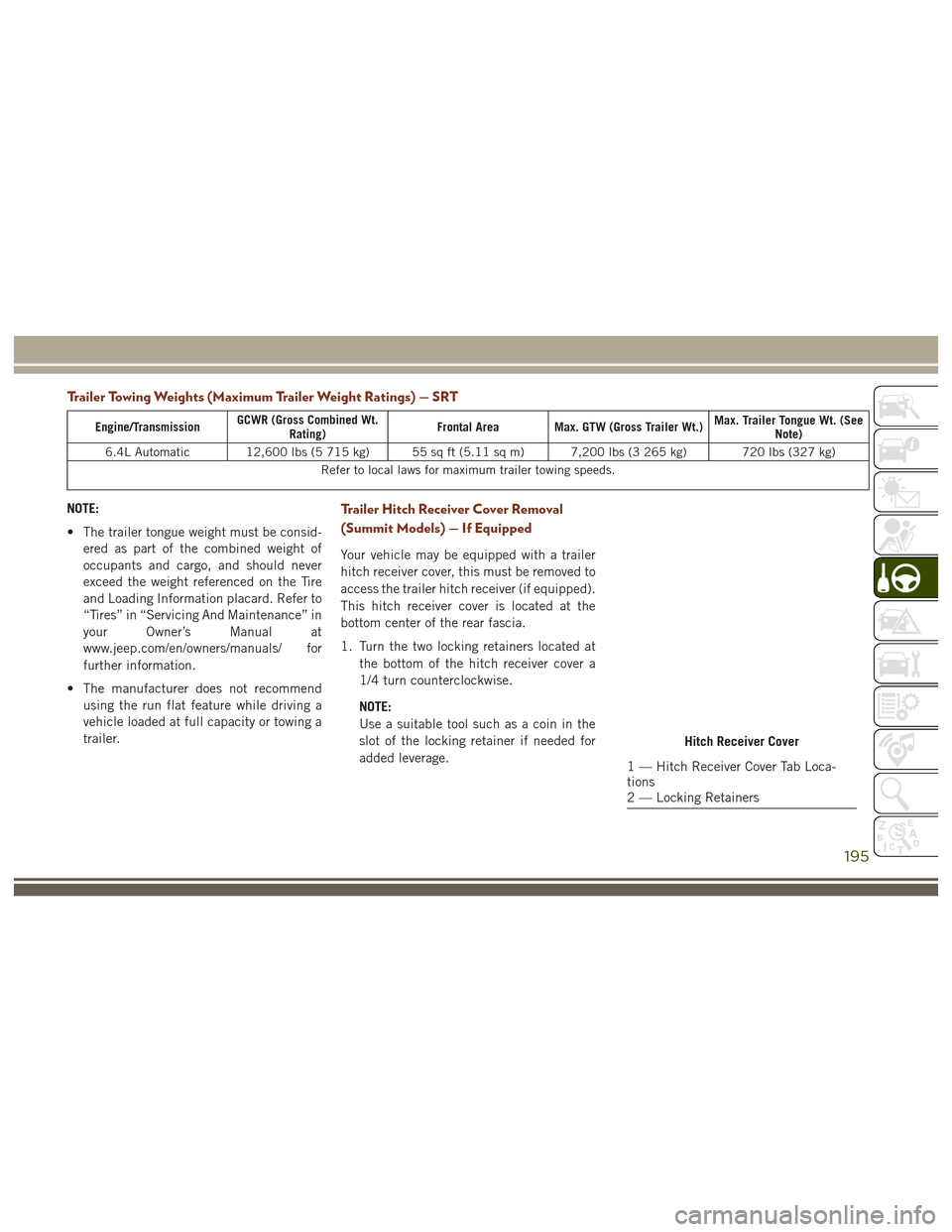
Trailer Towing Weights (Maximum Trailer Weight Ratings) — SRT
Engine/TransmissionGCWR (Gross Combined Wt.
Rating) Frontal Area Max. GTW (Gross Trailer Wt.) Max. Trailer Tongue Wt. (See
Note)
6.4L Automatic 12,600 lbs (5 715 kg) 55 sq ft (5.11 sq m) 7,200 lbs (3 265 kg) 720 lbs (327 kg) Refer to local laws for maximum trailer towing speeds.
NOTE:
• The trailer tongue weight must be consid-ered as part of the combined weight of
occupants and cargo, and should never
exceed the weight referenced on the Tire
and Loading Information placard. Refer to
“Tires” in “Servicing And Maintenance” in
your Owner’s Manual at
www.jeep.com/en/owners/manuals/ for
further information.
• The manufacturer does not recommend using the run flat feature while driving a
vehicle loaded at full capacity or towing a
trailer.Trailer Hitch Receiver Cover Removal
(Summit Models) — If Equipped
Your vehicle may be equipped with a trailer
hitch receiver cover, this must be removed to
access the trailer hitch receiver (if equipped).
This hitch receiver cover is located at the
bottom center of the rear fascia.
1. Turn the two locking retainers located at
the bottom of the hitch receiver cover a
1/4 turn counterclockwise.
NOTE:
Use a suitable tool such as a coin in the
slot of the locking retainer if needed for
added leverage.
Hitch Receiver Cover
1 — Hitch Receiver Cover Tab Loca-
tions
2 — Locking Retainers
195
Page 219 of 372
Jacking Instructions
WARNING!
Carefully follow these tire changing warn-
ings to help prevent personal injury or
damage to your vehicle:
• Always park on a firm, level surface asfar from the edge of the roadway as
possible before raising the vehicle.
• Turn on the Hazard Warning flasher.
• Chock the wheel diagonally opposite the
wheel to be raised.
• Set the parking brake firmly and set an
automatic transmission in PARK.
• Never start or run the engine with the
vehicle on a jack.
• Do not let anyone sit in the vehicle when
it is on a jack.
• Do not get under the vehicle when it is
on a jack. If you need to get under a
raised vehicle, take it to a service center
where it can be raised on a lift.
• Only use the jack in the positions indi-
cated and for lifting this vehicle during a
tire change.
WARNING!
• If working on or near a roadway, beextremely careful of motor traffic.
• To assure that spare tires, flat or in-
flated, are securely stowed, spares must
be stowed with the valve stem facing the
ground.
CAUTION!
Do not attempt to raise the vehicle by
jacking on locations other than those indi-
cated in the Jacking Instructions for this
vehicle.
1. Remove the spare tire, jack, and tools from storage. 2. Loosen (but do not remove) the wheel lug
nuts by turning them to the left, one turn,
while the wheel is still on the ground.
3. Assemble the jack and jacking tools.
Warning Label
Jack And Tools Assembled
217
Page 224 of 372
WARNING!
• Take care to avoid the radiator coolingfan whenever the hood is raised. It can
start anytime the ignition switch is ON.
You can be injured by moving fan
blades.
WARNING!
• Remove any metal jewelry such as rings,watch bands and bracelets that could
make an inadvertent electrical contact.
You could be seriously injured.
• Batteries contain sulfuric acid that can
burn your skin or eyes and generate
hydrogen gas which is flammable and
explosive. Keep open flames or sparks
away from the battery.
NOTE:
Be sure that the disconnected ends of the
cables do not touch while still connected to
the either vehicle.
1. Set the parking brake, shift the automatic transmission into PARK and turn the igni-
tion to LOCK.
2. Turn off the heater, radio, and all unnec- essary electrical accessories.
3. Remove the protective cover over the re- mote positive (+)battery post. Pull up-
ward on the cover to remove it. 4. If using another vehicle to jump-start the
battery, park the vehicle within the
jumper cables reach, set the parking
brake and make sure the ignition is OFF.
WARNING!
Do not allow vehicles to touch each other
as this could establish a ground connec-
tion and personal injury could result.
Jump-Starting Procedure
WARNING!
Failure to follow this jump-starting proce-
dure could result in personal injury or
property damage due to battery explosion.
CAUTION!
Failure to follow these procedures could
result in damage to the charging system of
the booster vehicle or the discharged ve-
hicle.
Remote Battery Posts
1 — Remote Positive (+)Post
2 — Remote Negative (–)Post
IN CASE OF EMERGENCY
222
Page 233 of 372
SERVICING AND MAINTENANCE
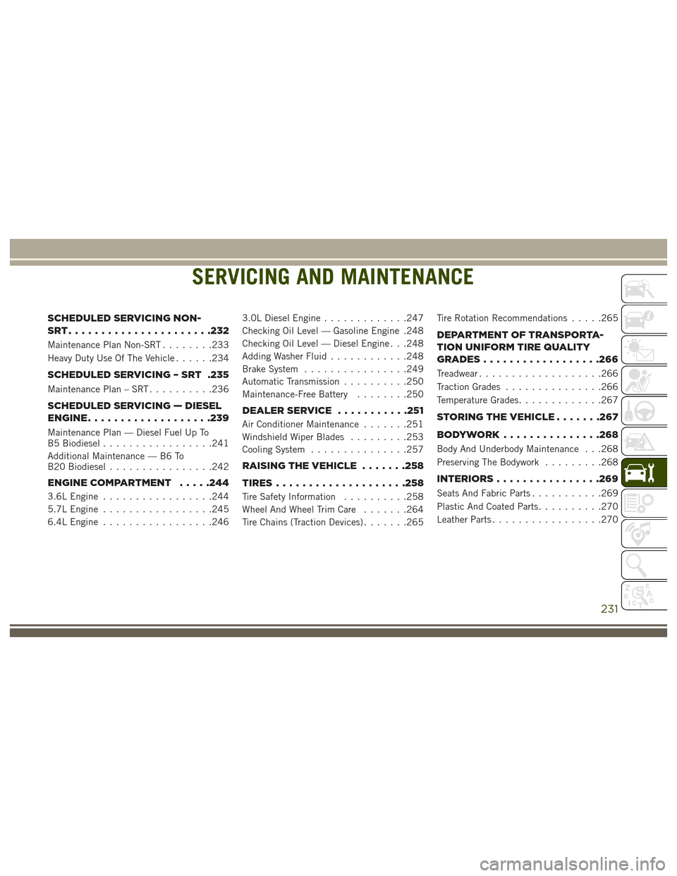
SCHEDULED SERVICING NON-
SRT......................232
Maintenance Plan Non-SRT........233
Heavy Duty Use Of The Vehicle ......234
SCHEDULED SERVICING – SRT .235
Maintenance Plan – SRT..........236
SCHEDULED SERVICING — DIESEL
ENGINE.................. .239
Maintenance Plan — Diesel Fuel Up To
B5 Biodiesel.................241
Additional Maintenance — B6 To
B20 Biodiesel ................242
ENGINE COMPARTMENT .....244
3.6L Engine.................244
5.7L Engine .................245
6.4L Engine .................246 3.0L Diesel Engine
.............247
Checking Oil Level — Gasoline Engine .248
Checking Oil Level — Diesel Engine . . .248
Adding Washer Fluid ............248
Brake System ................249
Automatic Transmission ..........250
Maintenance-Free Battery ........250
DEALERSERVICE .......... .251
Air Conditioner Maintenance.......251
Windshield Wiper Blades .........253
Cooling System ...............257
RAISINGTHEVEHICLE .......258
TIRES................... .258
Tire Safety Information..........258
Wheel And Wheel Trim Care .......264
Tire Chains (Traction Devices) .......265Tire Rotation Recommendations
.....265
DEPARTMENT OF TRANSPORTA-
TION UNIFORM TIRE QUALITY
GRADES................. .266
Treadwear...................266
Traction Grades ...............266
Temperature Grades .............267
STORINGTHEVEHICLE.......267
BODYWORK...............268
Body And Underbody Maintenance . . .268
Preserving The Bodywork .........268
INTERIORS............... .269
Seats And Fabric Parts...........269
Plastic And Coated Parts ..........270
Leather Parts .................270
SERVICING AND MAINTENANCE
231
Page 252 of 372
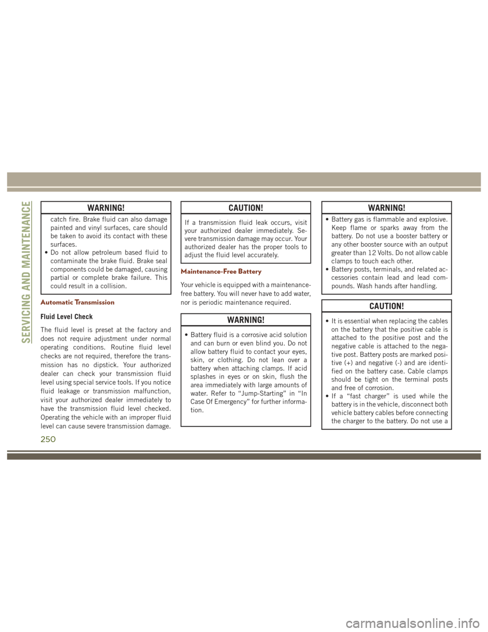
WARNING!
catch fire. Brake fluid can also damage
painted and vinyl surfaces, care should
be taken to avoid its contact with these
surfaces.
• Do not allow petroleum based fluid to
contaminate the brake fluid. Brake seal
components could be damaged, causing
partial or complete brake failure. This
could result in a collision.
Automatic Transmission
Fluid Level Check
The fluid level is preset at the factory and
does not require adjustment under normal
operating conditions. Routine fluid level
checks are not required, therefore the trans-
mission has no dipstick. Your authorized
dealer can check your transmission fluid
level using special service tools. If you notice
fluid leakage or transmission malfunction,
visit your authorized dealer immediately to
have the transmission fluid level checked.
Operating the vehicle with an improper fluid
level can cause severe transmission damage.
CAUTION!
If a transmission fluid leak occurs, visit
your authorized dealer immediately. Se-
vere transmission damage may occur. Your
authorized dealer has the proper tools to
adjust the fluid level accurately.
Maintenance-Free Battery
Your vehicle is equipped with a maintenance-
free battery. You will never have to add water,
nor is periodic maintenance required.
WARNING!
• Battery fluid is a corrosive acid solutionand can burn or even blind you. Do not
allow battery fluid to contact your eyes,
skin, or clothing. Do not lean over a
battery when attaching clamps. If acid
splashes in eyes or on skin, flush the
area immediately with large amounts of
water. Refer to “Jump-Starting” in “In
Case Of Emergency” for further informa-
tion.
WARNING!
• Battery gas is flammable and explosive.Keep flame or sparks away from the
battery. Do not use a booster battery or
any other booster source with an output
greater than 12 Volts. Do not allow cable
clamps to touch each other.
• Battery posts, terminals, and related ac-
cessories contain lead and lead com-
pounds. Wash hands after handling.
CAUTION!
• It is essential when replacing the cableson the battery that the positive cable is
attached to the positive post and the
negative cable is attached to the nega-
tive post. Battery posts are marked posi-
tive (+) and negative (-) and are identi-
fied on the battery case. Cable clamps
should be tight on the terminal posts
and free of corrosion.
• If a “fast charger” is used while the
battery is in the vehicle, disconnect both
vehicle battery cables before connecting
the charger to the battery. Do not use a
SERVICING AND MAINTENANCE
250