change time JEEP GRAND CHEROKEE 2017 WK2 / 4.G Owner's Manual
[x] Cancel search | Manufacturer: JEEP, Model Year: 2017, Model line: GRAND CHEROKEE, Model: JEEP GRAND CHEROKEE 2017 WK2 / 4.GPages: 372
Page 100 of 372
WARNING!
gage to assist in maintaining stability.
“Full Off” mode is only intended for
off-highway or off-road use.
• The Electronic Stability Control (ESC)
cannot prevent the natural laws of phys-
ics from acting on the vehicle, nor can it
increase the traction afforded by prevail-
ing road conditions. ESC cannot prevent
all accidents, including those resulting
from excessive speed in turns, driving on
very slippery surfaces, or hydroplaning.
ESC also cannot prevent collisions.
ESC Activation/Malfunction Indicator Light
and ESC OFF Indicator Light
The “ESC Activation/
Malfunction Indicator
Light” in the instrument
cluster will come on when
the ignition is turned to
the ON mode. It should go
out with the engine run-
ning. If the “ESC Activation/Malfunction In- dicator Light” comes on continuously with
the engine running, a malfunction has been
detected in the ESC system. If this light
remains on after several ignition cycles, and
the vehicle has been driven several miles
(kilometers) at speeds greater than 30 mph
(48 km/h), see your authorized dealer as soon
as possible to have the problem diagnosed
and corrected.
The “ESC Activation/Malfunction Indicator
Light” (located in the instrument cluster)
starts to flash as soon as the tires lose trac-
tion and the ESC system becomes active. The
“ESC Activation/Malfunction Indicator
Light” also flashes when TCS is active. If the
“ESC Activation/Malfunction Indicator
Light” begins to flash during acceleration,
ease up on the accelerator and apply as little
throttle as possible. Be sure to adapt your
speed and driving to the prevailing road con-
ditions.
NOTE:
• The “ESC Activation/Malfunction Indica-
tor Light” and the “ESC OFF Indicator
Light” come on momentarily each time
the ignition is turned ON. • Each time the ignition is turned ON, the
ESC system will be on even if it was turned
off previously.
• The ESC system will make buzzing or clicking sounds when it is active. This is
normal; the sounds will stop when ESC
becomes inactive following the maneuver
that caused the ESC activation.
The “ESC OFF Indicator
Light” indicates the cus-
tomer has elected to have
the Electronic Stability
Control (ESC) in a re-
duced mode.
Electronic Roll Mitigation (ERM)
This system anticipates the potential for
wheel lift by monitoring the driver’s steering
wheel input and the speed of the vehicle.
When ERM determines that the rate of
change of the steering wheel angle and vehi-
cle’s speed are sufficient to potentially cause
wheel lift, it then applies the appropriate
brake and may also reduce engine power to
lessen the chance that wheel lift will occur.
ERM can only reduce the chance of wheel lift
SAFETY
98
Page 108 of 372
• Changing the FCW status to “Off” pre-vents the system from warning you of a
possible collision with the vehicle in front
of you. If FCW is set to “Off”, “FCW OFF”
will appear in the instrument cluster
display.
Changing FCW Status
The FCW feature has three settings and can
be changed within the Uconnect System
Screen:
• Far
• Medium
• Near
Far
The far setting provides warnings for poten-
tial collisions more distant in front of the
vehicle, allowing the driver to have the most
reaction time to avoid a collision.
More cautious drivers that do not mind fre-
quent warnings may prefer this setting.
NOTE:
This setting gives you the most reaction time. Medium
The default status of FCW is the “Medium”
setting and the Active Braking is in the “On”
setting. This allows the system to warn the
driver of a possible collision with the vehicle
in front using audible/visual warnings and it
applies autonomous braking.
Near
Changing the FCW status to the “Near” set-
ting, allows the system to warn you of a
potential frontal collision when you are much
closer.
This setting provides less reaction time than
the “Far” setting, which allows for a more
dynamic driving experience.
More dynamic or aggressive drivers that want
to avoid frequent warnings may prefer this
setting.
NOTE:
Changing the Active Braking status to “Off”
prevents the system from providing autono-
mous braking, or additional brake support if
the driver is not braking adequately in the
event of a potential frontal collision. Active
braking can be turned “Off” in the Uconnect
controls settings.
Refer to your Owner's Manual at
www.jeep.com/en/owners/manuals/ for fur-
ther details.
WARNING!
Forward Collision Warning (FCW) is not
intended to avoid a collision on its own,
nor can FCW detect every type of potential
collision. The driver has the responsibility
to avoid a collision by controlling the ve-
hicle via braking and steering. Failure to
follow this warning could lead to serious
injury or death.
SAFETY
106
Page 131 of 372
Enhanced Accident Response System Reset
Procedure
In order to reset the Enhanced Accident Re-
sponse System functions after an event, the
ignition switch must be changed from igni-
tion START or ON/RUN to ignition OFF. Care-
fully check the vehicle for fuel leaks in the
engine compartment and on the ground near
the engine compartment and fuel tank before
resetting the system and starting the engine.
Maintaining Your Air Bag System
WARNING!
• Modifications to any part of the air bagsystem could cause it to fail when you
need it. You could be injured if the air
bag system is not there to protect you.
Do not modify the components or wiring,
including adding any kind of badges or
stickers to the steering wheel hub trim
cover or the upper right side of the in-
strument panel. Do not modify the front
bumper, vehicle body structure, or add
aftermarket side steps or running
boards.
WARNING!
• It is dangerous to try to repair any part ofthe air bag system yourself. Be sure to
tell anyone who works on your vehicle
that it has an air bag system.
• Do not attempt to modify any part of your
air bag system. The air bag may inflate
accidentally or may not function prop-
erly if modifications are made. Take your
vehicle to an authorized dealer for any
air bag system service. If your seat, in-
cluding your trim cover and cushion,
needs to be serviced in any way (includ-
ing removal or loosening/tightening of
seat attachment bolts), take the vehicle
to your authorized dealer. Only manufac-
turer approved seat accessories may be
used. If it is necessary to modify the air
bag system for persons with disabilities,
contact your authorized dealer.
Event Data Recorder (EDR)
This vehicle is equipped with an event data
recorder (EDR). The main purpose of an EDR
is to record, in certain crash or near crash-like
situations, such as an air bag deployment or hitting a road obstacle, data that will assist in
understanding how a vehicle’s systems per-
formed. The EDR is designed to record data
related to vehicle dynamics and safety sys-
tems for a short period of time, typically
30 seconds or less. The EDR in this vehicle is
designed to record such data as:
• How various systems in your vehicle were
operating;
• Whether or not the driver and passenger safety belts were buckled/fastened;
• How far (if at all) the driver was depressing the accelerator and/or brake pedal; and,
• How fast the vehicle was traveling.
• These data can help provide a better un- derstanding of the circumstances in which
crashes and injuries occur.
129
Page 145 of 372
SAFETY TIPS
Transporting Passengers
NEVER TRANSPORT PASSENGERS IN THE
CARGO AREA.
WARNING!
• Do not leave children or animals insideparked vehicles in hot weather. Interior
heat build-up may cause serious injury
or death.
• It is extremely dangerous to ride in a
cargo area, inside or outside of a vehicle.
In a collision, people riding in these
areas are more likely to be seriously
injured or killed.
• Do not allow people to ride in any area of
your vehicle that is not equipped with
seats and seat belts.
• Be sure everyone in your vehicle is in a
seat and using a seat belt properly.
Exhaust Gas
WARNING!
Exhaust gases can injure or kill. They con-
tain carbon monoxide (CO), which is col-
orless and odorless. Breathing it can make
you unconscious and can eventually poi-
son you. To avoid breathing (CO), follow
these safety tips:
• Do not run the engine in a closed garageor in confined areas any longer than
needed to move your vehicle in or out of
the area.
• If you are required to drive with the
trunk/liftgate/rear doors open, make sure
that all windows are closed and the cli-
mate control BLOWER switch is set at
high speed. DO NOT use the recircula-
tion mode.
• If it is necessary to sit in a parked vehicle
with the engine running, adjust your
heating or cooling controls to force out-
side air into the vehicle. Set the blower
at high speed. The best protection against carbon monoxide
entry into the vehicle body is a properly main-
tained engine exhaust system.
Whenever a change is noticed in the sound of
the exhaust system, when exhaust fumes can
be detected inside the vehicle, or when the
underside or rear of the vehicle is damaged,
have a competent mechanic inspect the com-
plete exhaust system and adjacent body ar-
eas for broken, damaged, deteriorated, or
mispositioned parts. Open seams or loose
connections could permit exhaust fumes to
seep into the passenger compartment. In
addition, inspect the exhaust system each
time the vehicle is raised for lubrication or oil
change. Replace as required.
Safety Checks You Should Make Inside
The Vehicle
Seat Belts
Inspect the seat belt system periodically,
checking for cuts, frays, and loose parts.
Damaged parts must be replaced immedi-
ately. Do not disassemble or modify the sys-
tem.
143
Page 152 of 372
NOTE:
If the ignition is left in the ACC or RUN
(engine not running) mode and the transmis-
sion is in PARK, the system will automatically
time out after 30 minutes of inactivity and
the ignition will cycle to the OFF mode.
ENGINE START/STOP Button Functions — With
Driver’s Foot OFF The Brake Pedal (In PARK Or
NEUTRAL Position)
The ENGINE START/STOP button operates
similar to an ignition switch. It has four
modes, OFF, ACC, RUN and START. To
change the ignition modes without starting
the vehicle and use the accessories follow
these steps:
• Starting with the ignition in the OFF mode,
• Push the ENGINE START/STOP buttononce to place the ignition to the ACC mode
(instrument cluster will display “ACC”),
• Push the ENGINE START/STOP button a second time to place the ignition to the
RUN mode (instrument cluster will display
“ON/RUN”), • Push the ENGINE START/STOP button a
third time to return the ignition to the OFF
mode (instrument cluster will display
“OFF”).
Cold Weather Operation (Below –22°F Or
−30°C)
To ensure reliable starting at these tempera-
tures, use of an externally powered electric
engine block heater (available from your Au-
thorized Dealer) is recommended.
After Starting
The idle speed is controlled automatically,
and it will decrease as the engine warms up.
If Engine Fails To Start
WARNING!
• Never pour fuel or other flammable liq-uid into the throttle body air inlet open-
ing in an attempt to start the vehicle.
This could result in flash fire causing
serious personal injury.
• Do not attempt to push or tow your
vehicle to get it started. Vehicles
WARNING!
equipped with an automatic transmis-
sion cannot be started this way. Un-
burned fuel could enter the catalytic
converter and once the engine has
started, ignite and damage the converter
and vehicle.
• If the vehicle has a discharged battery,
booster cables may be used to obtain a
start from a booster battery or the battery
in another vehicle. This type of start can
be dangerous if done improperly. Refer
to “Jump-Starting” in “In Case Of Emer-
gency” for further information.
After Starting
The idle speed is controlled automatically,
and it will decrease as the engine warms up.
STARTING PROCEDURES —
DIESEL ENGINES
Before starting your vehicle, adjust your seat,
both inside and outside mirrors, and fasten
your seat belts.
STARTING AND OPERATING
150
Page 157 of 372
Refer to or “Instrument Cluster Display”
in “Getting To Know Your Instrument
Panel” in your Owners Manual at
www.jeep.com/en/owners/manuals/ .
3. At the next vehicle stop (after turning off the STOP/START system), the engine will
not be stopped.
4. The STOP/START system will reset itself back to an ON condition every time the
ignition is turned off and back on.
To Manually Turn On The Stop/Start
System
Push the STOP/START Off switch (located on
the switch bank). The light on the switch will
turn off.
For complete details on the Stop/Start Sys-
tem refer to the “Stop/Start System” in the
“Starting And Operating” section located in
your Owners Manual at
www.jeep.com/en/owners/manuals/
ENGINE BREAK-IN
RECOMMENDATIONS
3.6L & 5.7L Engines
For vehicles equipped with the 3.6L or 5.7L use
the following engine break-in recommenda-
tions:A long break-in period is not required for
the drivetrain (engine, transmission, clutch,
and rear axle) in your new vehicle.
Drive moderately during the first 300 miles
(500 km). After the initial 60 miles
(100 km), speeds up to 50 or 55 mph (80 or
90 km/h) are desirable.
While cruising, brief full-throttle acceleration
within the limits of local traffic laws contrib-
utes to a good break-in. However, wide-open
throttle acceleration in low gear can be det-
rimental and should be avoided.
The engine oil, transmission fluid, and axle
lubricant installed at the factory is high-
quality and energy-conserving. Oil, fluid, and
lubricant changes should be consistent with
anticipated climate and conditions under which vehicle operations will occur. For the
recommended viscosity and quality grades,
refer to “Fluids And Lubricants” in "Techni-
cal Specifications”.CAUTION!
Never use Non-Detergent Oil or Straight
Mineral Oil in the engine or damage may
result.
NOTE:
A new engine may consume some oil during
its first few thousand miles (kilometers) of
operation. This should be considered a nor-
mal part of the break-in and not interpreted
as an indication of difficulty. Please check
your oil level with the engine oil indicator
often during the break in period. Add oil as
required.
155
Page 158 of 372
Diesel Engines
The diesel engine does not require a break-in
period due to its construction. Normal opera-
tion is allowed, providing the following rec-
ommendations are followed:
• Warm up the engine before placing it underload.
• Do not operate the engine at idle for pro- longed periods.
• Use the appropriate transmission gear to prevent engine lugging.
• Observe vehicle oil pressure and tempera- ture indicators.
• Check the coolant and oil levels frequently.
• Vary throttle position at highway speeds when carrying or towing significant weight.
NOTE:
Light duty operation such as light trailer
towing or no load operation will extend the
time before the engine is at full efficiency.
Reduced fuel economy and power may be
seen at this time. The engine oil installed in the engine at the
factory is a high-quality energy conserving
type lubricant. Oil changes should be consis-
tent with anticipated climate conditions un-
der which vehicle operations will occur. The
recommended viscosity and quality grades
are shown under “Fluids And Lubricants” in
"Technical Specifications” in this manual.
NON-DETERGENT OR STRAIGHT MINERAL
OILS MUST NEVER BE USED.
SRT Engines
The following tips will be helpful in obtaining
optimum performance and maximum dura-
bility for your new SRT Vehicle.
Despite modern technology and World Class
manufacturing methods, the moving parts of
the vehicle must still wear in with each other.
This wearing in occurs mainly during the first
500 miles (805 km) and continues through
the first oil change interval.
It is recommended for the operator to observe
the following driving behaviors during the
new vehicle break-in period:
0 to 100 miles (0 to 161 km):
• Do not allow the engine to operate at idle
for an extended period of time.
• Depress the accelerator pedal slowly and not more than halfway to avoid rapid ac-
celeration.
• Avoid aggressive braking.
• Drive with the engine speed less than 3,500 RPM.
• Maintain vehicle speed below 55 mph (88 km/h) and observe local speed limits.
100 to 300 miles (161 to 483 km):
• Depress the accelerator pedal slowly and not more than halfway to avoid rapid ac-
celeration in lower gears (1st to 3rd gears).
• Avoid aggressive braking.
• Drive with the engine speed less than 5,000 RPM.
• Maintain vehicle speed below 70 mph (112 km/h) and observe local speed
limits.
STARTING AND OPERATING
156
Page 169 of 372
(40 km/h) the vehicle height will be auto-
matically lowered to OR1. Refer to “Driv-
ing Tips” in “Starting And Operating” for
further information.
• Aero Mode (Lowers the vehicle approxi-
mately 0.6 inches (15 mm) – This position
provides improved aerodynamics by lower-
ing the vehicle. The vehicle will automati-
cally enter Aero Mode when the vehicle
speed remains between 52 mph (83 km/h)
and 56 mph (90 km/h) for greater than
20 seconds or if the vehicle speed exceeds
56 mph (90 km/h). The vehicle will return
to NRH from Aero Mode if the vehicle
speed remains between 20 mph (32 km/h)
and 25 mph (40 km/h) for greater than
20 seconds or if the vehicle speed falls
below 20 mph (32 km/h). The vehicle will
enter Aero Mode, regardless of vehicle
speed if the vehicle is in “SPORT” mode.
• Entry/Exit Mode (Lowers the vehicle approxi-
mately 1.6 inces (40 mm) – This position
lowers the vehicle for easier passenger
entry and exit as well as lowering the rear
of the vehicle for easier loading and un-
loading of cargo. To enter Entry/Exit Mode,
push the “DOWN” button once from (NRH) while the vehicle speed is below
25 mph (40 km/h). Once the vehicle
speed goes below 15 mph (24 km/h) the
vehicle height will begin to lower. If the
vehicle speed remains between 15 mph
(24 km/h) and 25 mph (40 km/h) for
greater than 60 seconds, or the vehicle
speed exceeds 25 mph (40 km/h) the
Entry/Exit Mode change will be cancelled.
To exit Entry/Exit Mode, press the “Up”
button once while in Entry/Exit Mode or
drive the vehicle over 15 mph (24 km/h).
NOTE:
Automatic lowering of the vehicle into Entry/
Exit Mode can be enabled through the
Uconnect Touch-Screen Radio. If this feature
is enabled, the vehicle will only lower if the
gear selector is in "PARK", the terrain switch
is in "AUTO", the transfer-case is in "AUTO”
and the vehicle level should be either in
Normal or Aero Mode. The Vehicle will not
automatically lower if the air suspension level
is in Off Rd 2 or Off Rd 1. If the vehicle is
equipped with Intrusion Theft Module (ITM),
the lowering will be suppressed when the
ignition is switched OFF and the door is open
to prevent setting the alarm off. The Selec-Terrain switch will automatically
change the vehicle to the proper height based
on the position of the Selec-Terrain switch.
The height can be changed from the default
Selec-Terrain setting by normal use of the air
suspension buttons. Refer to “Selec-Terrain”
in “Starting And Operating” for further infor-
mation.
The system requires that the engine be run-
ning for all changes. When lowering the ve-
hicle all of the doors, including the liftgate,
must be closed. If a door is opened at any
time while the vehicle is lowering the change
will not be completed until the open door(s) is
closed.
The Quadra-Lift air suspension system uses a
lifting and lowering pattern which keeps the
headlights from incorrectly shining into on-
coming traffic. When raising the vehicle, the
rear of the vehicle will move up first and then
the front. When lowering the vehicle, the
front will move down first and then the rear.
167
Page 171 of 372
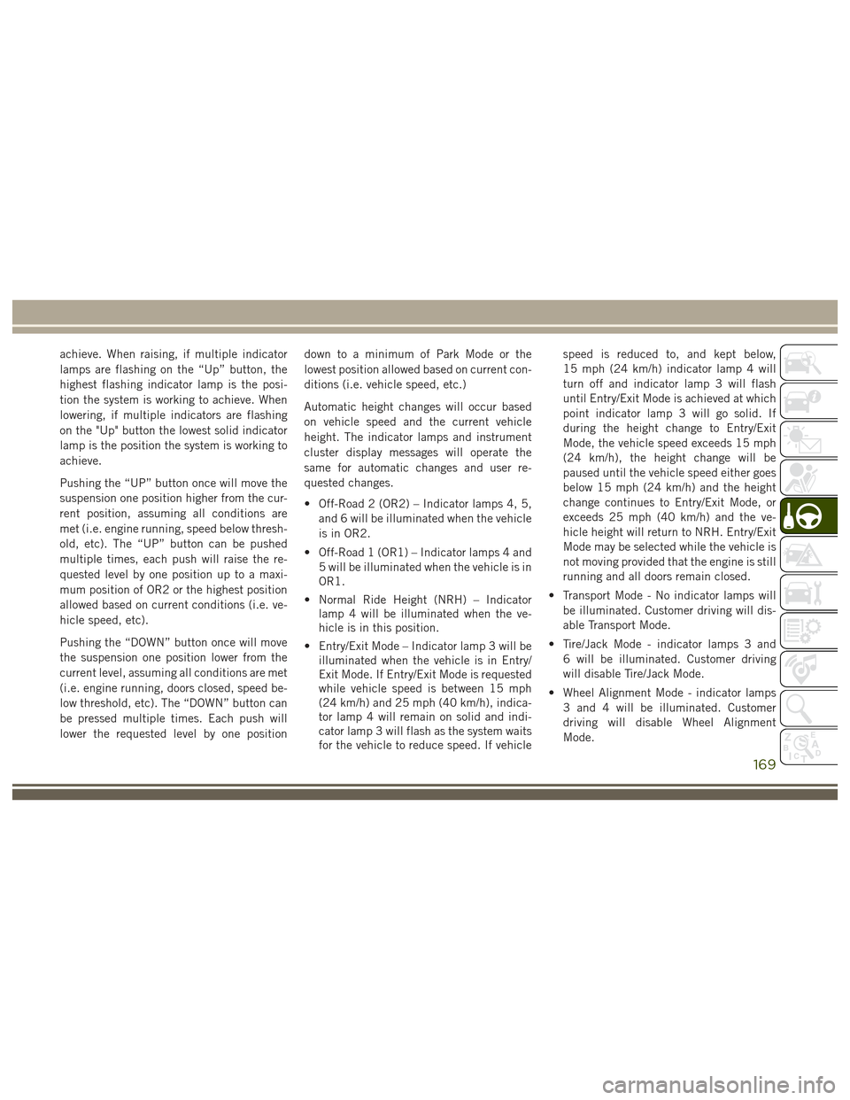
achieve. When raising, if multiple indicator
lamps are flashing on the “Up” button, the
highest flashing indicator lamp is the posi-
tion the system is working to achieve. When
lowering, if multiple indicators are flashing
on the "Up" button the lowest solid indicator
lamp is the position the system is working to
achieve.
Pushing the “UP” button once will move the
suspension one position higher from the cur-
rent position, assuming all conditions are
met (i.e. engine running, speed below thresh-
old, etc). The “UP” button can be pushed
multiple times, each push will raise the re-
quested level by one position up to a maxi-
mum position of OR2 or the highest position
allowed based on current conditions (i.e. ve-
hicle speed, etc).
Pushing the “DOWN” button once will move
the suspension one position lower from the
current level, assuming all conditions are met
(i.e. engine running, doors closed, speed be-
low threshold, etc). The “DOWN” button can
be pressed multiple times. Each push will
lower the requested level by one positiondown to a minimum of Park Mode or the
lowest position allowed based on current con-
ditions (i.e. vehicle speed, etc.)
Automatic height changes will occur based
on vehicle speed and the current vehicle
height. The indicator lamps and instrument
cluster display messages will operate the
same for automatic changes and user re-
quested changes.
• Off-Road 2 (OR2) – Indicator lamps 4, 5,
and 6 will be illuminated when the vehicle
is in OR2.
• Off-Road 1 (OR1) – Indicator lamps 4 and 5 will be illuminated when the vehicle is in
OR1.
• Normal Ride Height (NRH) – Indicator lamp 4 will be illuminated when the ve-
hicle is in this position.
• Entry/Exit Mode – Indicator lamp 3 will be illuminated when the vehicle is in Entry/
Exit Mode. If Entry/Exit Mode is requested
while vehicle speed is between 15 mph
(24 km/h) and 25 mph (40 km/h), indica-
tor lamp 4 will remain on solid and indi-
cator lamp 3 will flash as the system waits
for the vehicle to reduce speed. If vehicle speed is reduced to, and kept below,
15 mph (24 km/h) indicator lamp 4 will
turn off and indicator lamp 3 will flash
until Entry/Exit Mode is achieved at which
point indicator lamp 3 will go solid. If
during the height change to Entry/Exit
Mode, the vehicle speed exceeds 15 mph
(24 km/h), the height change will be
paused until the vehicle speed either goes
below 15 mph (24 km/h) and the height
change continues to Entry/Exit Mode, or
exceeds 25 mph (40 km/h) and the ve-
hicle height will return to NRH. Entry/Exit
Mode may be selected while the vehicle is
not moving provided that the engine is still
running and all doors remain closed.
• Transport Mode - No indicator lamps will be illuminated. Customer driving will dis-
able Transport Mode.
• Tire/Jack Mode - indicator lamps 3 and 6 will be illuminated. Customer driving
will disable Tire/Jack Mode.
• Wheel Alignment Mode - indicator lamps 3 and 4 will be illuminated. Customer
driving will disable Wheel Alignment
Mode.
169
Page 172 of 372
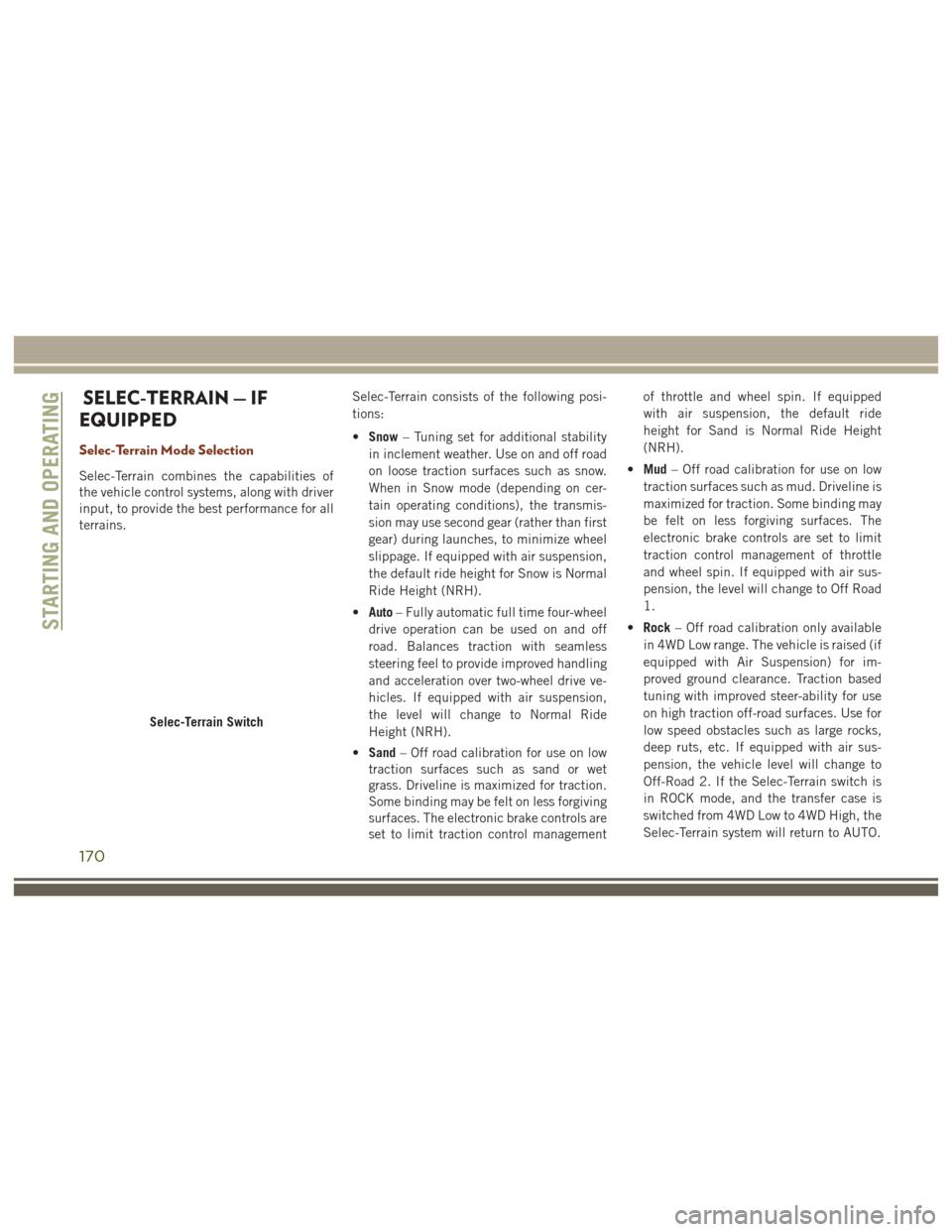
SELEC-TERRAIN — IF
EQUIPPED
Selec-Terrain Mode Selection
Selec-Terrain combines the capabilities of
the vehicle control systems, along with driver
input, to provide the best performance for all
terrains. Selec-Terrain consists of the following posi-
tions:
•
Snow – Tuning set for additional stability
in inclement weather. Use on and off road
on loose traction surfaces such as snow.
When in Snow mode (depending on cer-
tain operating conditions), the transmis-
sion may use second gear (rather than first
gear) during launches, to minimize wheel
slippage. If equipped with air suspension,
the default ride height for Snow is Normal
Ride Height (NRH).
• Auto – Fully automatic full time four-wheel
drive operation can be used on and off
road. Balances traction with seamless
steering feel to provide improved handling
and acceleration over two-wheel drive ve-
hicles. If equipped with air suspension,
the level will change to Normal Ride
Height (NRH).
• Sand – Off road calibration for use on low
traction surfaces such as sand or wet
grass. Driveline is maximized for traction.
Some binding may be felt on less forgiving
surfaces. The electronic brake controls are
set to limit traction control management of throttle and wheel spin. If equipped
with air suspension, the default ride
height for Sand is Normal Ride Height
(NRH).
• Mud – Off road calibration for use on low
traction surfaces such as mud. Driveline is
maximized for traction. Some binding may
be felt on less forgiving surfaces. The
electronic brake controls are set to limit
traction control management of throttle
and wheel spin. If equipped with air sus-
pension, the level will change to Off Road
1.
• Rock – Off road calibration only available
in 4WD Low range. The vehicle is raised (if
equipped with Air Suspension) for im-
proved ground clearance. Traction based
tuning with improved steer-ability for use
on high traction off-road surfaces. Use for
low speed obstacles such as large rocks,
deep ruts, etc. If equipped with air sus-
pension, the vehicle level will change to
Off-Road 2. If the Selec-Terrain switch is
in ROCK mode, and the transfer case is
switched from 4WD Low to 4WD High, the
Selec-Terrain system will return to AUTO.
Selec-Terrain Switch
STARTING AND OPERATING
170