climate control JEEP GRAND CHEROKEE 2017 WK2 / 4.G Owner's Manual
[x] Cancel search | Manufacturer: JEEP, Model Year: 2017, Model line: GRAND CHEROKEE, Model: JEEP GRAND CHEROKEE 2017 WK2 / 4.GPages: 372
Page 50 of 372
IconDescription
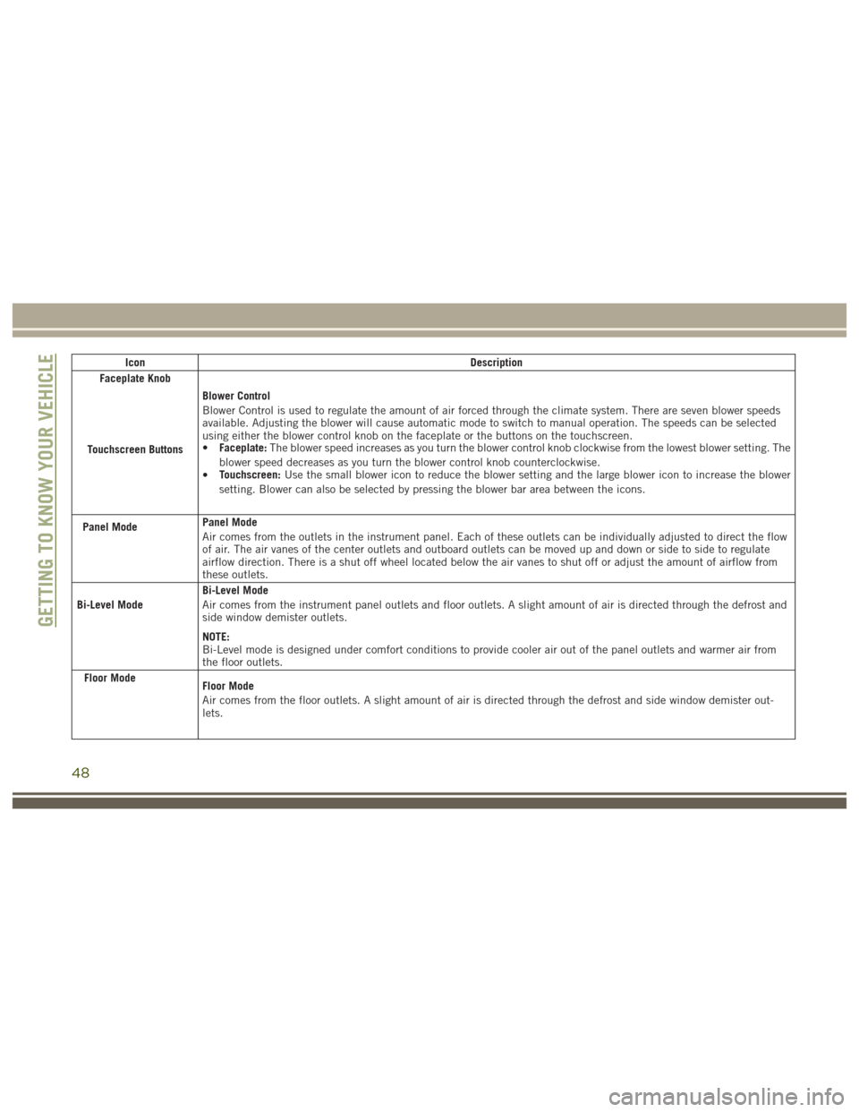
Faceplate Knob
Touchscreen Buttons
Blower Control
Blower Control is used to regulate the amount of air forced through the climate system. There are seven blower speeds
available. Adjusting the blower will cause automatic mode to switch to manual operation. The speeds can be selected
using either the blower control knob on the faceplate or the buttons on the touchscreen.
• Faceplate: The blower speed increases as you turn the blower control knob clockwise from the lowest blower setting. The
blower speed decreases as you turn the blower control knob counterclockwise.
• Touchscreen:
Use the small blower icon to reduce the blower setting and the large blower icon to increase the blower
setting. Blower can also be selected by pressing the blower bar area between the icons.
Panel Mode
Panel Mode
Air comes from the outlets in the instrument panel. Each of these outlets can be individually adjusted to direct the flow
of air. The air vanes of the center outlets and outboard outlets can be moved up and down or side to side to regulate
airflow direction. There is a shut off wheel located below the air vanes to shut off or adjust the amount of airflow from
these outlets.
Bi-Level Mode
Bi-Level Mode
Air comes from the instrument panel outlets and floor outlets. A slight amount of air is directed through the defrost and
side window demister outlets.
NOTE:
Bi-Level mode is designed under comfort conditions to provide cooler air out of the panel outlets and warmer air from
the floor outlets.
Floor Mode
Floor Mode
Air comes from the floor outlets. A slight amount of air is directed through the defrost and side window demister out-
lets.
GETTING TO KNOW YOUR VEHICLE
48
Page 51 of 372
IconDescription
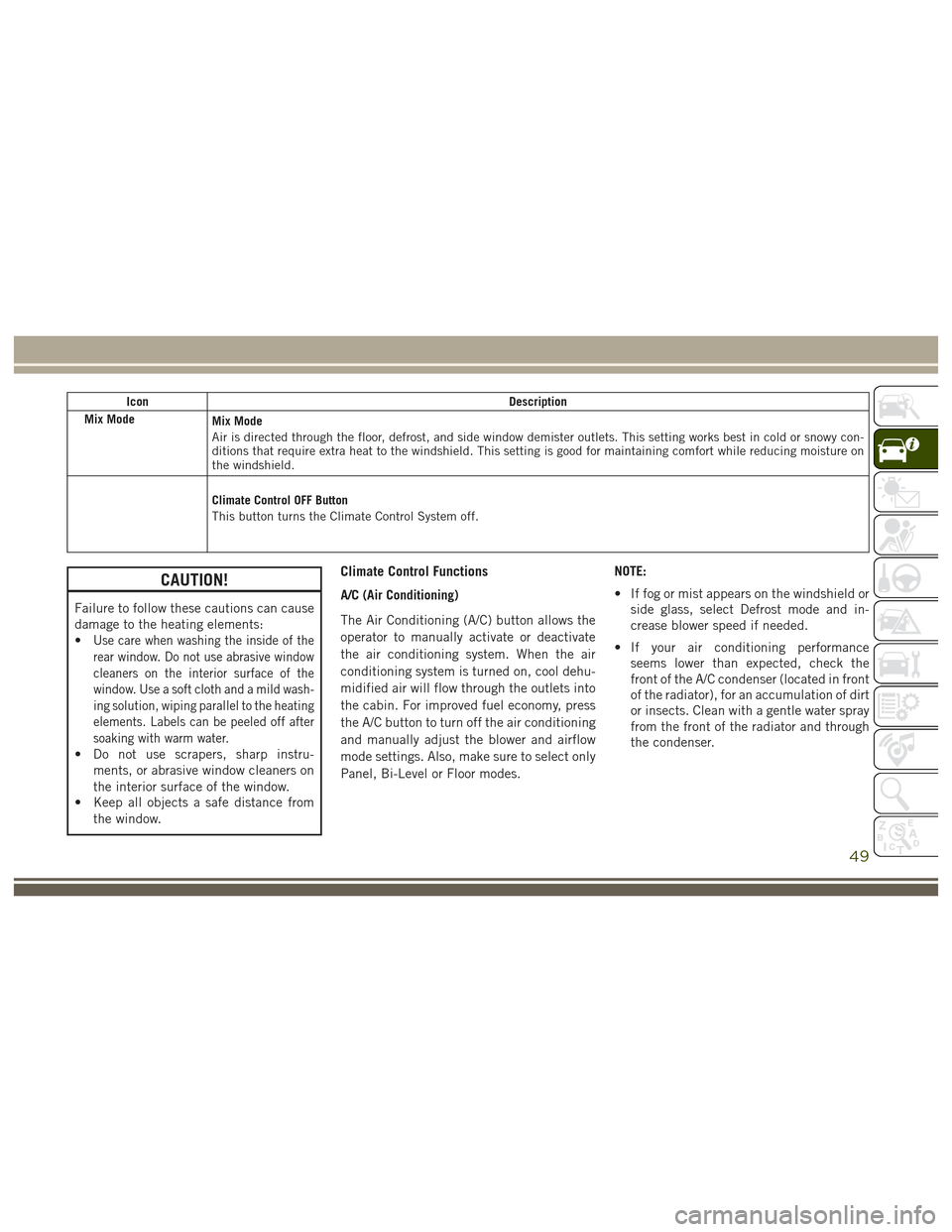
Mix Mode
Mix Mode
Air is directed through the floor, defrost, and side window demister outlets. This setting works best in cold or snowy con-
ditions that require extra heat to the windshield. This setting is good for maintaining comfort while reducing moisture on
the windshield.
Climate Control OFF Button
This button turns the Climate Control System off.
CAUTION!
Failure to follow these cautions can cause
damage to the heating elements:
•
Usecarewhenwashingtheinsideofthe
rear window. Do not use abrasive window
cleaners on the interior surface of the
window. Use a soft cloth and a mild wash-
ing solution, wiping parallel to the heating
elements. Labels can be peeled off after
soaking with warm water.
• Do not use scrapers, sharp instru- ments, or abrasive window cleaners on
the interior surface of the window.
• Keep all objects a safe distance from
the window.
Climate Control Functions
A/C (Air Conditioning)
The Air Conditioning (A/C) button allows the
operator to manually activate or deactivate
the air conditioning system. When the air
conditioning system is turned on, cool dehu-
midified air will flow through the outlets into
the cabin. For improved fuel economy, press
the A/C button to turn off the air conditioning
and manually adjust the blower and airflow
mode settings. Also, make sure to select only
Panel, Bi-Level or Floor modes. NOTE:
• If fog or mist appears on the windshield or
side glass, select Defrost mode and in-
crease blower speed if needed.
• If your air conditioning performance seems lower than expected, check the
front of the A/C condenser (located in front
of the radiator), for an accumulation of dirt
or insects. Clean with a gentle water spray
from the front of the radiator and through
the condenser.
49
Page 52 of 372
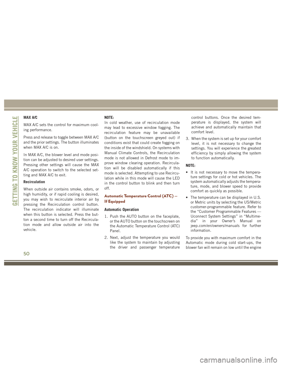
MAX A/C
MAX A/C sets the control for maximum cool-
ing performance.
Press and release to toggle between MAX A/C
and the prior settings. The button illuminates
when MAX A/C is on.
In MAX A/C, the blower level and mode posi-
tion can be adjusted to desired user settings.
Pressing other settings will cause the MAX
A/C operation to switch to the selected set-
ting and MAX A/C to exit.
Recirculation
When outside air contains smoke, odors, or
high humidity, or if rapid cooling is desired,
you may wish to recirculate interior air by
pressing the Recirculation control button.
The recirculation indicator will illuminate
when this button is selected. Press the but-
ton a second time to turn off the Recircula-
tion mode and allow outside air into the
vehicle.NOTE:
In cold weather, use of recirculation mode
may lead to excessive window fogging. The
recirculation feature may be unavailable
(button on the touchscreen greyed out) if
conditions exist that could create fogging on
the inside of the windshield. On systems with
Manual Climate Controls, the Recirculation
mode is not allowed in Defrost mode to im-
prove window clearing operation. Recircula-
tion will be disabled automatically if this
mode is selected. Attempting to use Recircu-
lation while in this mode will cause the LED
in the control button to blink and then turn
off.
Automatic Temperature Control (ATC) —
If Equipped
Automatic Operation
1. Push the AUTO button on the faceplate,
or the AUTO button on the touchscreen on
the Automatic Temperature Control (ATC)
Panel.
2. Next, adjust the temperature you would like the system to maintain by adjusting
the driver and passenger temperature control buttons. Once the desired tem-
perature is displayed, the system will
achieve and automatically maintain that
comfort level.
3. When the system is set up for your comfort level, it is not necessary to change the
settings. You will experience the greatest
efficiency by simply allowing the system
to function automatically.
NOTE:
• It is not necessary to move the tempera- ture settings for cold or hot vehicles. The
system automatically adjusts the tempera-
ture, mode, and blower speed to provide
comfort as quickly as possible.
• The temperature can be displayed in U.S. or Metric units by selecting the US/Metric
customer-programmable feature. Refer to
the “Customer Programmable Features —
Uconnect System Settings” in “Multime-
dia” in your Owner’s Manual on
jeep.com/en/owners/manuals for further
information.
To provide you with maximum comfort in the
Automatic mode during cold start-ups, the
blower fan will remain on low until the engine
GETTING TO KNOW YOUR VEHICLE
50
Page 53 of 372
warms up. The blower will increase in speed
and transition into Auto mode.
Manual Operation Override
This system offers a full complement of
manual override features. The AUTO symbol
in the front ATC display will be turned off
when the system is being used in the manual
mode.
NOTE:
The system will not automatically sense the
presence of fog, mist or ice on the wind-
shield. DEFROST mode must be manually
selected to clear the windshield and side
glass.
Operating Tips
NOTE:
Refer to the chart at the end of this section
for suggested control settings for various
weather conditions.
Summer Operation
The engine cooling system must be protected
with a high-quality antifreeze coolant to pro-
vide proper corrosion protection and to pro-
tect against engine overheating. OAT coolant
(conforming to MS.90032) is recommended.
Winter Operation
To ensure the best possible heater and de-
froster performance, make sure the engine
cooling system is functioning properly and
the proper amount, type, and concentration
of coolant is used. Use of the air Recircula-
tion mode during Winter months is not rec-
ommended, because it may cause window
fogging.
Vacation/Storage
Before you store your vehicle, or keep it out of
service (i.e., vacation) for two weeks or more,
run the air conditioning system at idle for
about five minutes, in fresh air with the
blower setting on high. This will ensure ad-
equate system lubrication to minimize the
possibility of compressor damage when the
system is started again.
Window Fogging
Vehicle windows tend to fog on the inside in
mild, rainy and/or humid weather. To clear
the windows, select Defrost or Mix mode and
increase the front blower speed. Do not use
the Recirculation mode without A/C for long
periods, as fogging may occur.
Outside Air Intake
Make sure the air intake, located directly in
front of the windshield, is free of obstructions
such as leaves. Leaves collected in the air
intake may reduce airflow, and if they enter
the plenum, they could plug the water drains.
In winter months, make sure the air intake is
clear of ice, slush, and snow.
Cabin Air Filter
The climate control system filters out dust
and pollen from the air. Contact your autho-
rized dealer to service your cabin air filter,
and to have it replaced when needed.
51
Page 62 of 372
When the liftgate button on the key fob is
pushed two times, the turn signals will flash
twice to signal that the liftgate is opening or
closing (if Flash Lamps with Lock is enabled in
the Uconnect settings), and the liftgate chime
will be audible. Refer to "Uconnect Settings" in
"Multimedia” for further information.
NOTE:
• In the event of a power malfunction to theliftgate, an emergency liftgate latch re-
lease can be used to open the liftgate. The
emergency liftgate latch release can be
accessed through a snap-in cover located
on the liftgate trim panel.
• If liftgate is left open for an extended period of time, the liftgate may need to be
closed manually to reset power liftgate
functionality.
WARNING!
During power operation, personal injury or
cargo damage may occur. Ensure the lift-
gate travel path is clear. Make sure the
liftgate is closed and latched before driv-
ing away. NOTE:
• The power liftgate buttons will not operate
if the vehicle is in gear or the vehicle
speed is above 0 MPH (0 km/h).
• The power liftgate will not operate in tem- peratures below −22°F (−30°C) or tem-
peratures above 150° F (65° C). Be sure to
remove any buildup of snow or ice from the
liftgate before pushing any of the power
liftgate switches.
• If anything obstructs the power liftgate while it is closing or opening, the liftgate
will automatically reverse to the closed or
open position, provided it meets sufficient
resistance.
• There are also pinch sensors attached to the side of the liftgate. Light pressure
anywhere along these strips will cause the
liftgate to return to the open position.
• If the liftgate is not fully open, push the liftgate button on the key fob twice to
operate the liftgate.
• If the electronic liftgate release is pushed while the power liftgate is closing, the
liftgate will reverse to the full open posi-
tion. • If the electronic liftgate release is pushed
while the power liftgate is opening, the
liftgate motor will disengage to allow
manual operation.
• If the power liftgate encounters multiple obstructions within the same cycle, the
system will automatically stop and the
liftgate must be opened or closed
manually.
WARNING!
• Driving with the liftgate open can allowpoisonous exhaust gases into your ve-
hicle. You and your passengers could be
injured by these fumes. Keep the liftgate
closed when you are operating the ve-
hicle.
• If you are required to drive with the
liftgate open, make sure that all win-
dows are closed, and the climate control
blower switch is set at high speed. Do
not use the recirculation mode.
GETTING TO KNOW YOUR VEHICLE
60
Page 97 of 372
For vehicles not equipped with an instrument
cluster display, perform the following steps:
1. Center the steering wheel (front wheelspointing straight forward).
2. Shift the transmission into PARK.
3. Apply the parking brake.
4. Start the engine.
5. Rotate the steering wheel slightly more than one-half turn to the left.
6. Push the “ESC Off” button located in the lower switch bank below the climate con-
trol four times within twenty seconds. The
“ESC Off Indicator Light” should turn on
and turn off two times.
7. Rotate the steering wheel back to center and then an additional slighty more than
one-half turn to the right.
8. Turn the ignition to the OFF mode and then back to ON. If the sequence was
completed properly, the “ESC Off Indica-
tor Light” will blink several times to con-
firm HSA is disabled.
9. Repeat these steps if you want to return this feature to its previous setting.Towing With HSA
HSA will also provide assistance to mitigate
roll back while towing a trailer.
WARNING!
• If you use a trailer brake controller withyour trailer, the trailer brakes may be
activated and deactivated with the brake
switch. If so, there may not be enough
brake pressure to hold both the vehicle
and the trailer on a hill when the brake
pedal is released. In order to avoid roll-
ing down an incline while resuming ac-
celeration, manually activate the trailer
brake or apply more vehicle brake pres-
sure prior to releasing the brake pedal.
• HSA is not a parking brake. Always apply
the parking brake fully when leaving your
vehicle. Also, be certain to leave the
transmission in PARK.
• Failure to follow these warnings can re-
sult in a collision or serious personal
injury.
Traction Control System (TCS)
This system monitors the amount of wheel
spin of each of the driven wheels. If wheel
spin is detected, the TCS may apply brake
pressure to the spinning wheel(s) and/or re-
duce engine power to provide enhanced ac-
celeration and stability. A feature of the TCS,
Brake Limited Differential (BLD), functions
similar to a limited slip differential and con-
trols the wheel spin across a driven axle. If
one wheel on a driven axle is spinning faster
than the other, the system will apply the
brake of the spinning wheel. This will allow
more engine torque to be applied to the wheel
that is not spinning. BLD may remain en-
abled even if TCS and ESC are in a reduced
mode.
Electronic Stability Control (ESC)
This system enhances directional control and
stability of the vehicle under various driving
conditions. ESC corrects for oversteering or
understeering of the vehicle by applying the
brake of the appropriate wheel(s) to assist in
counteracting the oversteer or understeer
condition. Engine power may also be reduced
to help the vehicle maintain the desired path.
95
Page 206 of 372
HAZARD WARNING
FLASHERS
Control
The Hazard Warning flasher switch is located
on the switch bank just above the climate
controls.
Push the switch to turn on the Hazard Warn-
ing flasher. When the switch is activated, all
directional turn signals will flash on and off towarn oncoming traffic of an emergency. Push
the switch a second time to turn off the
Hazard Warning flashers.
This is an emergency warning system and it
should not be used when the vehicle is in
motion. Use it when your vehicle is disabled
and it is creating a safety hazard for other
motorists.
When you must leave the vehicle to seek
assistance, the Hazard Warning flashers will
continue to operate even though the ignition
is placed in the OFF position. NOTE:
With extended use, the Hazard Warning
flashers may discharge the battery.
BULB REPLACEMENT
Replacement Bulbs
Interior Bulbs
Bulb Number
Glove Compartment Lamp 194
Grab Handle Lamp L002825W5W
Overhead Console Reading Lamps VT4976
Rear Cargo Lamp 214–2
Visor Vanity Lamp V26377
Underpanel Courtesy Lamps 906
Instrument Cluster (General Illumination) 103
Telltale/Hazard Lamp 74
IN CASE OF EMERGENCY
204
Page 214 of 372
CavityCartridge Fuse Micro Fuse Description
F42 –20 Amp Yellow Horn
F44 –10 Amp Red Diagnostic Port
F49 –10 Amp Red Integrated Central Stack/Climate Control
F50 –20 Amp Yellow Air Suspension Control Module - If Equipped
F51 –15 Amp Blue Ignition Node Module/Keyless Ignition/Steering Column
Lock
F52 –5 Amp Tan Battery Sensor
F53 –20 Amp Yellow Trailer Tow – Left Turn/Stop Lights — If Equipped
F56 –15 Amp Blue Additional Content (Diesel engine only)
F57 –20 Amp Yellow NOX Sensor
F58 –15 Amp Blue HID Headlamps LH — If Equipped
F59 –10 Amp Red Purging Pump (Diesel engine only)
F60 –15 Amp Blue Transmission Control Module
F61 –10 Amp Red Transmission Control Module/PM Sensor (Diesel engine
only)
F62 –10 Amp Red Air Conditioning Clutch
F63 –20 Amp Yellow Ignition Coils (Gas), Urea Heater (Diesel)
F64 –25 Amp Clear Fuel Injectors/Powertrain
F66 –10 Amp Red Sunroof/Passenger Window Switches/Rain Sensor
F67 –15 Amp Blue CD/DVD/Bluetooth Hands-free Module — If Equipped
F68 –20 Amp Yellow Rear Wiper Motor
F69 –15 Amp Blue Spotlight Feed — If Equipped
F70 –20 Amp Yellow Fuel Pump Motor
IN CASE OF EMERGENCY
212
Page 216 of 372
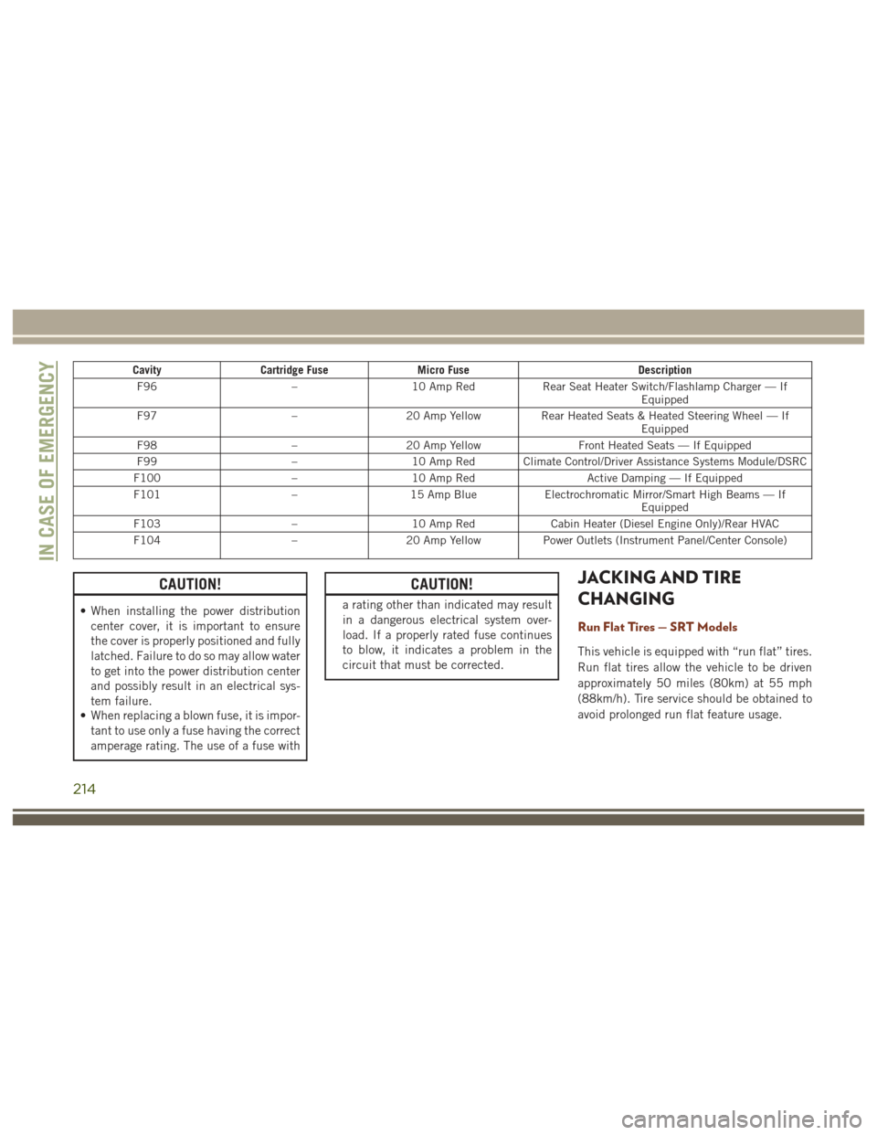
CavityCartridge Fuse Micro Fuse Description
F96 –10 Amp Red Rear Seat Heater Switch/Flashlamp Charger — If
Equipped
F97 –20 Amp Yellow Rear Heated Seats & Heated Steering Wheel — If
Equipped
F98 –20 Amp Yellow Front Heated Seats — If Equipped
F99 –10 Amp Red Climate Control/Driver Assistance Systems Module/DSRC
F100 –10 Amp Red Active Damping — If Equipped
F101 –15 Amp Blue Electrochromatic Mirror/Smart High Beams — If
Equipped
F103 –10 Amp Red Cabin Heater (Diesel Engine Only)/Rear HVAC
F104 –20 Amp Yellow Power Outlets (Instrument Panel/Center Console)
CAUTION!
• When installing the power distribution
center cover, it is important to ensure
the cover is properly positioned and fully
latched. Failure to do so may allow water
to get into the power distribution center
and possibly result in an electrical sys-
tem failure.
• When replacing a blown fuse, it is impor-
tant to use only a fuse having the correct
amperage rating. The use of a fuse with
CAUTION!
a rating other than indicated may result
in a dangerous electrical system over-
load. If a properly rated fuse continues
to blow, it indicates a problem in the
circuit that must be corrected.
JACKING AND TIRE
CHANGING
Run Flat Tires — SRT Models
This vehicle is equipped with “run flat” tires.
Run flat tires allow the vehicle to be driven
approximately 50 miles (80km) at 55 mph
(88km/h). Tire service should be obtained to
avoid prolonged run flat feature usage.
IN CASE OF EMERGENCY
214
Page 268 of 372
These effects can be reduced by timely rota-
tion of tires. The benefits of rotation are
especially worthwhile with aggressive tread
designs such as those on On/Off-Road type
tires. Rotation will increase tread life, help to
maintain mud, snow, and wet traction levels,
and contribute to a smooth, quiet ride.
Refer to the “Maintenance Plan” for the
proper maintenance intervals. More frequent
rotation is permissible if desired. The reasons
for any rapid or unusual wear should be
corrected prior to rotation being performed.
NOTE:
The premium Tire Pressure Monitor System
will automatically locate the pressure values
displayed in the correct vehicle position fol-
lowing a tire rotation.
The suggested rotation method is the
“rearward-cross” shown in the following dia-
gram.
DEPARTMENT OF
TRANSPORTATION
UNIFORM TIRE QUALITY
GRADES
The following tire grading categories were
established by the National Highway Traffic
Safety Administration. The specific grade
rating assigned by the tire's manufacturer in
each category is shown on the sidewall of the
tires on your vehicle.
All passenger vehicle tires must conform to
Federal safety requirements in addition to
these grades.
Treadwear
The Treadwear grade is a comparative rating,
based on the wear rate of the tire when tested
under controlled conditions on a specified
government test course. For example, a tire
graded 150 would wear one and one-half
times as well on the government course as a
tire graded 100. The relative performance of
tires depends upon the actual conditions of
their use, however, and may depart signifi-
cantly from the norm due to variations in
driving habits, service practices, and differ-
ences in road characteristics and climate.
Traction Grades
The Traction grades, from highest to lowest,
are AA, A, B, and C. These grades represent
the tire's ability to stop on wet pavement, as
measured under controlled conditions on
specified government test surfaces of asphalt
and concrete. A tire marked C may have poor
traction performance.
Tire Rotation
SERVICING AND MAINTENANCE
266