ESP JEEP GRAND CHEROKEE 2017 WK2 / 4.G Owner's Manual
[x] Cancel search | Manufacturer: JEEP, Model Year: 2017, Model line: GRAND CHEROKEE, Model: JEEP GRAND CHEROKEE 2017 WK2 / 4.GPages: 372
Page 130 of 372
If A Deployment Occurs
The front air bags are designed to deflate
immediately after deployment.
NOTE:
Front and/or side air bags will not deploy in
all collisions. This does not mean something
is wrong with the air bag system.
If you do have a collision which deploys the
air bags, any or all of the following may occur:
• The air bag material may sometimes causeabrasions and/or skin reddening to the
occupants as the air bags deploy and un-
fold. The abrasions are similar to friction
rope burns or those you might get sliding
along a carpet or gymnasium floor. They
are not caused by contact with chemicals.
They are not permanent and normally heal
quickly. However, if you haven’t healed
significantly within a few days, or if you
have any blistering, see your doctor imme-
diately.
• As the air bags deflate, you may see some smoke-like particles. The particles are a
normal by-product of the process that gen-
erates the non-toxic gas used for air bag
inflation. These airborne particles may ir- ritate the skin, eyes, nose, or throat. If you
have skin or eye irritation, rinse the area
with cool water. For nose or throat irrita-
tion, move to fresh air. If the irritation
continues, see your doctor. If these par-
ticles settle on your clothing, follow the
garment manufacturer’s instructions for
cleaning.
Do not drive your vehicle after the air bags
have deployed. If you are involved in another
collision, the air bags will not be in place to
protect you.
WARNING!
Deployed air bags and seat belt preten-
sioners cannot protect you in another col-
lision. Have the air bags, seat belt preten-
sioners, and the seat belt retractor
assemblies replaced by an authorized
dealer immediately. Also, have the Occu-
pant Restraint Controller System serviced
as well. NOTE:
• Air bag covers may not be obvious in the
interior trim, but they will open during air
bag deployment.
• After any collision, the vehicle should be taken to an authorized dealer
immediately.
Enhanced Accident Response System
In the event of an impact, if the communica-
tion network remains intact, and the power
remains intact, depending on the nature of
the event, the ORC will determine whether to
have the Enhanced Accident Response Sys-
tem perform the following functions:
• Cut off fuel to the engine.
• Flash hazard lights as long as the batteryhas power or until the hazard light button
is pressed. The hazard lights can be deac-
tivated by pressing the hazard light but-
ton.
• Turn on the interior lights, which remain on as long as the battery has power.
• Unlock the power door locks.
SAFETY
128
Page 131 of 372
Enhanced Accident Response System Reset
Procedure
In order to reset the Enhanced Accident Re-
sponse System functions after an event, the
ignition switch must be changed from igni-
tion START or ON/RUN to ignition OFF. Care-
fully check the vehicle for fuel leaks in the
engine compartment and on the ground near
the engine compartment and fuel tank before
resetting the system and starting the engine.
Maintaining Your Air Bag System
WARNING!
• Modifications to any part of the air bagsystem could cause it to fail when you
need it. You could be injured if the air
bag system is not there to protect you.
Do not modify the components or wiring,
including adding any kind of badges or
stickers to the steering wheel hub trim
cover or the upper right side of the in-
strument panel. Do not modify the front
bumper, vehicle body structure, or add
aftermarket side steps or running
boards.
WARNING!
• It is dangerous to try to repair any part ofthe air bag system yourself. Be sure to
tell anyone who works on your vehicle
that it has an air bag system.
• Do not attempt to modify any part of your
air bag system. The air bag may inflate
accidentally or may not function prop-
erly if modifications are made. Take your
vehicle to an authorized dealer for any
air bag system service. If your seat, in-
cluding your trim cover and cushion,
needs to be serviced in any way (includ-
ing removal or loosening/tightening of
seat attachment bolts), take the vehicle
to your authorized dealer. Only manufac-
turer approved seat accessories may be
used. If it is necessary to modify the air
bag system for persons with disabilities,
contact your authorized dealer.
Event Data Recorder (EDR)
This vehicle is equipped with an event data
recorder (EDR). The main purpose of an EDR
is to record, in certain crash or near crash-like
situations, such as an air bag deployment or hitting a road obstacle, data that will assist in
understanding how a vehicle’s systems per-
formed. The EDR is designed to record data
related to vehicle dynamics and safety sys-
tems for a short period of time, typically
30 seconds or less. The EDR in this vehicle is
designed to record such data as:
• How various systems in your vehicle were
operating;
• Whether or not the driver and passenger safety belts were buckled/fastened;
• How far (if at all) the driver was depressing the accelerator and/or brake pedal; and,
• How fast the vehicle was traveling.
• These data can help provide a better un- derstanding of the circumstances in which
crashes and injuries occur.
129
Page 158 of 372
Diesel Engines
The diesel engine does not require a break-in
period due to its construction. Normal opera-
tion is allowed, providing the following rec-
ommendations are followed:
• Warm up the engine before placing it underload.
• Do not operate the engine at idle for pro- longed periods.
• Use the appropriate transmission gear to prevent engine lugging.
• Observe vehicle oil pressure and tempera- ture indicators.
• Check the coolant and oil levels frequently.
• Vary throttle position at highway speeds when carrying or towing significant weight.
NOTE:
Light duty operation such as light trailer
towing or no load operation will extend the
time before the engine is at full efficiency.
Reduced fuel economy and power may be
seen at this time. The engine oil installed in the engine at the
factory is a high-quality energy conserving
type lubricant. Oil changes should be consis-
tent with anticipated climate conditions un-
der which vehicle operations will occur. The
recommended viscosity and quality grades
are shown under “Fluids And Lubricants” in
"Technical Specifications” in this manual.
NON-DETERGENT OR STRAIGHT MINERAL
OILS MUST NEVER BE USED.
SRT Engines
The following tips will be helpful in obtaining
optimum performance and maximum dura-
bility for your new SRT Vehicle.
Despite modern technology and World Class
manufacturing methods, the moving parts of
the vehicle must still wear in with each other.
This wearing in occurs mainly during the first
500 miles (805 km) and continues through
the first oil change interval.
It is recommended for the operator to observe
the following driving behaviors during the
new vehicle break-in period:
0 to 100 miles (0 to 161 km):
• Do not allow the engine to operate at idle
for an extended period of time.
• Depress the accelerator pedal slowly and not more than halfway to avoid rapid ac-
celeration.
• Avoid aggressive braking.
• Drive with the engine speed less than 3,500 RPM.
• Maintain vehicle speed below 55 mph (88 km/h) and observe local speed limits.
100 to 300 miles (161 to 483 km):
• Depress the accelerator pedal slowly and not more than halfway to avoid rapid ac-
celeration in lower gears (1st to 3rd gears).
• Avoid aggressive braking.
• Drive with the engine speed less than 5,000 RPM.
• Maintain vehicle speed below 70 mph (112 km/h) and observe local speed
limits.
STARTING AND OPERATING
156
Page 163 of 372
• The system may revert to automatic shiftmode if a fault or overheat condition is
detected.
NOTE:
When Selec-Speed or Hill Descent Control is
enabled, AutoStick is not active.
To disengage AutoStick, return the gear se-
lector to the DRIVE position, or press and
hold the (+) shift paddle (if the gear selector
is already in DRIVE) until "D" is once again
indicated in the instrument cluster. You can
shift in or out of AutoStick at any time with-
out taking your foot off the accelerator pedal.
WARNING!
Do not downshift for additional engine
braking on a slippery surface. The drive
wheels could lose their grip and the ve-
hicle could skid, causing a collision or
personal injury.
SPORT MODE — IF
EQUIPPED
Your vehicle is equipped with a Sport Mode
feature. This mode is a configuration set up
for typical enthusiast driving. The engine,
transmission, and steering systems are all set
to their SPORT settings. Sport Mode will
provide improved throttle response and modi-
fied shifting for an enhanced driving experi-
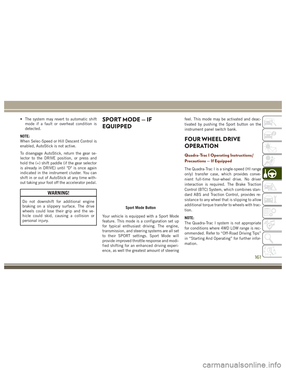
ence, as well the greatest amount of steering feel. This mode may be activated and deac-
tivated by pushing the Sport button on the
instrument panel switch bank.
FOUR WHEEL DRIVE
OPERATION
Quadra-Trac I Operating Instructions/
Precautions — If Equipped
The Quadra-Trac I is a single-speed (HI range
only) transfer case, which provides conve-
nient full-time four-wheel drive. No driver
interaction is required. The Brake Traction
Control (BTC) System, which combines stan-
dard ABS and Traction Control, provides re-
sistance to any wheel that is slipping to allow
additional torque transfer to wheels with trac-
tion.
NOTE:
The Quadra-Trac I system is not appropriate
for conditions where 4WD LOW range is rec-
ommended. Refer to “Off-Road Driving Tips”
in “Starting And Operating” for further infor-
mation.
Sport Mode Button
161
Page 180 of 372
• Pushing the normal (Fixed Speed) SPEEDCONTROL ON/OFF button will result in
turning ON (changing to) the normal
(Fixed Speed) Speed Control mode.
Refer to your Owner's Manual at
www.jeep.com/en/owners/manuals/ for fur-
ther information.
WARNING!
Adaptive Cruise Control (ACC) is a conve-
nience system. It is not a substitute for
active driving involvement. It is always the
driver’s responsibility to be attentive of
road, traffic, and weather conditions, ve-
hicle speed, distance to the vehicle ahead;
and, most importantly, brake operation to
ensure safe operation of the vehicle under
all road conditions. Your complete atten-
tion is always required while driving to
maintain safe control of your vehicle. Fail-
ure to follow these warnings can result in a
collision and death or serious personal
injury.
The ACC system:
• Does not react to pedestrians, oncoming vehicles, and stationary objects (e.g., a
WARNING!
stopped vehicle in a traffic jam or a
disabled vehicle).
• Cannot take street, traffic, and weather
conditions into account, and may be
limited upon adverse sight distance con-
ditions.
• Does not always fully recognize complex
driving conditions, which can result in
wrong or missing distance warnings.
• Will bring the vehicle to a complete stop
while following a target vehicle and hold
the vehicle for 2 seconds in the stop
position. If the target vehicle does not
start moving within two seconds the ACC
system will display a message that the
system will release the brakes and that
the brakes must be applied manually. An
audible chime will sound when the
brakes are released.
You should switch off the ACC system:
• When driving in fog, heavy rain, heavy
snow, sleet, heavy traffic, and complex
driving situations (i.e., in highway con-
struction zones).
WARNING!
• When entering a turn lane or highway offramp; when driving on roads that are
winding, icy, snow-covered, slippery, or
have steep uphill or downhill slopes.
• When towing a trailer up or down steep
slopes.
• When circumstances do not allow safe
driving at a constant speed.
The Cruise Control system has two control
modes:
• Adaptive Cruise Control mode for main-
taining an appropriate distance between
vehicles.
• Normal (fixed speed) electronic speed
control mode for cruising at a constant
preset speed. For additional informa-
tion, refer to “Normal (Fixed Speed)
Cruise Control Mode” in your Owner’s
Manual at
www.jeep.com/en/owners/manuals/
Normal (fixed speed) electronic speed con-
trol will not react to preceding vehicles. Al-
ways be aware of the mode selected.
You can change the mode by using the
Cruise Control buttons. The two control
STARTING AND OPERATING
178
Page 182 of 372
• Clean the ParkSense sensors regularly,taking care not to scratch or damage them.
The sensors must not be covered with ice,
snow, slush, mud, dirt or debris. Failure to
do so can result in the system not working
properly. The ParkSense system might not
detect an obstacle behind the fascia/
bumper, or it could provide a false indica-
tion that an obstacle is behind the fascia/
bumper.
• Use the ParkSense switch to turn the ParkSense system OFF if objects such as
bicycle carriers, trailer hitches, etc. are
placed within 12 in (30 cm) from the rear
fascia/bumper. Failure to do so can result
in the system misinterpreting a close ob-
ject as a sensor problem, causing the
“PARKSENSE UNAVAILABLE SERVICE
REQUIRED” message to appear in the
instrument cluster display.
• ParkSense should be disabled when the liftgate is in the open position and the
vehicle is in REVERSE. An open liftgate
could provide a false indication that an
obstacle is behind the vehicle.WARNING!
• Drivers must be careful when backing upeven when using ParkSense. Always
check carefully behind your vehicle,
look behind you, and be sure to check
for pedestrians, animals, other vehicles,
obstructions, and blind spots before
backing up. You are responsible for
safety and must continue to pay atten-
tion to your surroundings. Failure to do
so can result in serious injury or death.
• Before using ParkSense, it is strongly
recommended that the ball mount and
hitch ball assembly is disconnected
from the vehicle when the vehicle is not
used for towing. Failure to do so can
result in injury or damage to vehicles or
obstacles because the hitch ball will be
much closer to the obstacle than the
rear fascia when the loudspeaker sounds
the continuous tone. Also, the sensors
could detect the ball mount and hitch
ball assembly, depending on its size and
shape, giving a false indication that an
obstacle is behind the vehicle.
CAUTION!
• ParkSense is only a parking aid and it isunable to recognize every obstacle, in-
cluding small obstacles. Parking curbs
might be temporarily detected or not
detected at all. Obstacles located above
or below the sensors will not be detected
when they are in close proximity.
• The vehicle must be driven slowly when
using ParkSense in order to be able to
stop in time when an obstacle is de-
tected. It is recommended that the
driver looks over his/her shoulder when
using ParkSense.
PARKSENSE FRONT AND
REAR PARK ASSIST
Sensors
The four ParkSense sensors, located in the
rear fascia/bumper, monitor the area behind
the vehicle that is within the sensors field of
view. The sensors can detect obstacles from
approximately 12 inches (30 cm) up to
STARTING AND OPERATING
180
Page 184 of 372
Operation With A Trailer
The operation of the sensors is automatically
deactivated when the trailer's electric plug is
inserted in the vehicle's tow hook socket. The
sensors are automatically reactivated when
the trailer's cable plug is removed.
General Warnings
If “PARKSENSE UNAVAILABLE WIPE REAR
SENSORS" or "PARKSENSE UNAVAILABLE
WIPE FRONT SENSORS” appears in the in-
strument cluster display, clean the
ParkSense sensors with water, car wash soap
and a soft cloth. Do not use rough or hard
cloths. Do not scratch or poke the sensors.
Otherwise, you could damage the sensors.
PARKSENSE ACTIVE PARK
ASSIST SYSTEM — IF
EQUIPPED
The ParkSense Active Park Assist system is
intended to assist the driver during parallel
and perpendicular parking maneuvers by
identifying a proper parking space, providing
audible/visual instructions, and controllingthe steering wheel. The ParkSense Active
Park Assist system is defined as “semi-
automatic” since the driver maintains control
of the accelerator, gear selector and brakes.
Depending on the driver's parking maneuver
selection, the ParkSense Active Park Assist
system is capable of maneuvering a vehicle
into a parallel or a perpendicular parking
space on either side (i.e., driver side or pas-
senger side).
NOTE:
• The driver is always responsible for con-
trolling the vehicle, responsible for any
surrounding objects, and must intervene
as required.
• The system is provided to assist the driver and not to substitute the driver.
• During a semi-automatic maneuver, if the driver touches the steering wheel after
being instructed to remove their hands
from the steering wheel, the system will
cancel, and the driver will be required to
manually complete the parking maneuver. • The system may not work in all conditions
(e.g. environmental conditions such as
heavy rain, snow, etc., or if searching for a
parking space that has surfaces that will
absorb the ultrasonic sensor waves).
• New vehicles from the dealership must have at least 30 miles (48 km) accumu-
lated before the ParkSense Active Park
Assist system is fully calibrated and per-
forms accurately. This is due to the sys-
tem’s dynamic vehicle calibration to im-
prove the performance of the feature. The
system will also continuously perform the
dynamic vehicle calibration to account for
differences such as over or under inflated
tires and new tires.
Enabling And Disabling The ParkSense Active
Park Assist System
The ParkSense Active Park Assist system can
be enabled and disabled with the ParkSense
Active Park Assist switch, located on the
switch panel below the Uconnect display.
STARTING AND OPERATING
182
Page 195 of 372
CAUTION!
• Never add anything other than DEF tothe tank – especially any form of hydro-
carbon such as diesel fuel, fuel system
additives, gasoline, or any other
petroleum-based product. Even a very
small amount of these, less than
100 parts per million or less than 1 oz.
per 78 gallons (295 liters) will contami-
nate the entire DEF system and will
require replacement. If owners use a
container, funnel or nozzle when refilling
the tank, it should either be new or one
that is has only been used for adding
DEF. MOPAR provides an attachable
nozzle with its DEF for this purpose. 3. Stop filling the DEF tank immediately
when any of the following happen: DEF
stops flowing from the fill bottle into the
DEF fill inlet, DEF splashes out the fill
inlet, or a DEF pump nozzle automatically
shuts off.
4. Reinstall cap onto DEF fill inlet.
TRAILER TOWING
Trailer Towing Weights (Maximum Trailer
Weight Ratings) — Non SRT
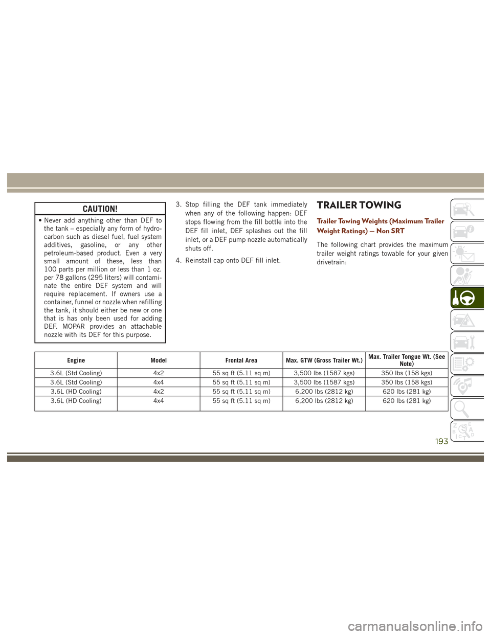
The following chart provides the maximum
trailer weight ratings towable for your given
drivetrain:
Engine ModelFrontal Area Max. GTW (Gross Trailer Wt.) Max. Trailer Tongue Wt. (See
Note)
3.6L (Std Cooling) 4x255 sq ft (5.11 sq m) 3,500 lbs (1587 kgs) 350 lbs (158 kgs)
3.6L (Std Cooling) 4x455 sq ft (5.11 sq m) 3,500 lbs (1587 kgs) 350 lbs (158 kgs)
3.6L (HD Cooling) 4x255 sq ft (5.11 sq m) 6,200 lbs (2812 kg) 620 lbs (281 kg)
3.6L (HD Cooling) 4x455 sq ft (5.11 sq m) 6,200 lbs (2812 kg) 620 lbs (281 kg)
193
Page 205 of 372
IN CASE OF EMERGENCY
HAZARD WARNING
FLASHERS................204
Control....................204
BULB REPLACEMENT ........204
Replacement Bulbs.............204
Bulb Replacement .............206
FUSES ...................209
General Information.............209
Underhood Fuses ..............209
JACKING AND TIRE
CHANGING............... .214
Run Flat Tires — SRT Models .......214
Jack/Spare Tire Stowage ..........215
Changing Procedure ............221
JUMP-STARTING............221
Preparations For Jump-Starting ......221
Jump-Starting Procedure .........222
REFUELING IN EMERGENCY . . .224
IF YOUR ENGINE OVERHEATS .224 MANUAL PARK RELEASE
.....224
FREEING A STUCK VEHICLE . . .226
TOWING A DISABLED
VEHICLE ................ .227
Two-Wheel Drive Models..........228
Four-Wheel Drive Models .........229
ENHANCED ACCIDENT RESPONSE
SYSTEM(EARS) ........... .229
EVENT DATA RECORDER
(EDR)................... .229
IN CASE OF EMERGENCY
203
Page 211 of 372
Center High-Mounted Stop Lamp (CHMSL)
The center high mounted stop lamp is an
LED. Service at an authorized dealer.
Rear License Lamp
The rear license lamps are LEDs. See your
authorized dealer for service.
FUSES
WARNING!
• When replacing a blown fuse, always usean appropriate replacement fuse with
the same amp rating as the original fuse.
Never replace a fuse with another fuse of
higher amp rating. Never replace a
blown fuse with metal wires or any other
material. Failure to use proper fuses may
result in serious personal injury, fire
and/or property damage.
• Before replacing a fuse, make sure that
the ignition is off and that all the other
services are switched off and/or disen-
gaged.
• If the replaced fuse blows again, contact
an authorized dealer.
• If a general protection fuse for safety
systems (air bag system, braking sys-
tem), power unit systems (engine sys-
tem, gearbox system) or steering system
blows, contact an authorized dealer.
General Information
The fuses protect electrical systems against
excessive current.
When a device does not work you must check
the electrical circuit inside the fuse for a
break/melt.
Also please be aware that when using power
outlets for extended periods of time with the
engine off may result in vehicle battery dis-
charge.
Underhood Fuses
The Power Distribution Center is located in
the engine compartment near the battery.
This center contains cartridge fuses, micro
fuses, relays, and circuit breakers. A descrip-
tion of each fuse and component may be
stamped on the inside cover, otherwise the
cavity number of each fuse is stamped on the
inside cover that corresponds to the following
chart.
Center High-Mounted Stop Lamp
209