engine JEEP GRAND CHEROKEE 2017 WK2 / 4.G Workshop Manual
[x] Cancel search | Manufacturer: JEEP, Model Year: 2017, Model line: GRAND CHEROKEE, Model: JEEP GRAND CHEROKEE 2017 WK2 / 4.GPages: 372
Page 167 of 372
8. Release the brake pedal for five secondsand ensure that there is no vehicle
movement.
NOTE:
If shift conditions/interlocks are not met, a
“To Tow Vehicle Safely, Read Neutral Shift
Procedure in Owner’s Manual” message will
flash from the instrument cluster display.
Refer to “Instrument Cluster Display” in
“Getting To Know Your Instrument Panel” for
further information.
Shifting Out Of NEUTRAL (N)
Use the following procedure to prepare your
vehicle for normal usage.
1. Bring the vehicle to a complete stop.
2. Firmly apply the parking brake.
3. Start the engine.
4. Press and hold the brake pedal.
5. Shift the transmission into NEUTRAL. 6. Using a ballpoint pen or similar object,
push and hold the recessed transfer case
NEUTRAL (N) button (located by the se-
lector switch) for one second.
7. When the NEUTRAL (N) indicator light turns off, release the NEUTRAL (N)
button.
8. After the NEUTRAL (N) button has been released, the transfer case will shift to the
position indicated by the selector switch.
Quadra-Drive II System — If Equipped
The optional Quadra-Drive II System features
two torque transfer couplings. The couplings
include an Electronic Limited-Slip Differen-
tial (ELSD) rear axle and the Quadra-Trac II
transfer case. The optional ELSD axle is fully
automatic and requires no driver input to
operate. Under normal driving conditions,
the unit functions as a standard axle, balanc-
ing torque evenly between left and right
wheels. With a traction difference between
left and right wheels, the coupling will sense
a speed difference. As one wheel begins to
spin faster than the other, torque will auto-
matically transfer from the wheel that has
less traction, to the wheel that has traction.
While the transfer case and axle coupling
differ in design, their operation is similar.
Follow the Quadra-Trac II transfer case shift-
ing information, preceding this section, for
shifting this system.
NEUTRAL (N) Switch
165
Page 169 of 372
(40 km/h) the vehicle height will be auto-
matically lowered to OR1. Refer to “Driv-
ing Tips” in “Starting And Operating” for
further information.
• Aero Mode (Lowers the vehicle approxi-
mately 0.6 inches (15 mm) – This position
provides improved aerodynamics by lower-
ing the vehicle. The vehicle will automati-
cally enter Aero Mode when the vehicle
speed remains between 52 mph (83 km/h)
and 56 mph (90 km/h) for greater than
20 seconds or if the vehicle speed exceeds
56 mph (90 km/h). The vehicle will return
to NRH from Aero Mode if the vehicle
speed remains between 20 mph (32 km/h)
and 25 mph (40 km/h) for greater than
20 seconds or if the vehicle speed falls
below 20 mph (32 km/h). The vehicle will
enter Aero Mode, regardless of vehicle
speed if the vehicle is in “SPORT” mode.
• Entry/Exit Mode (Lowers the vehicle approxi-
mately 1.6 inces (40 mm) – This position
lowers the vehicle for easier passenger
entry and exit as well as lowering the rear
of the vehicle for easier loading and un-
loading of cargo. To enter Entry/Exit Mode,
push the “DOWN” button once from (NRH) while the vehicle speed is below
25 mph (40 km/h). Once the vehicle
speed goes below 15 mph (24 km/h) the
vehicle height will begin to lower. If the
vehicle speed remains between 15 mph
(24 km/h) and 25 mph (40 km/h) for
greater than 60 seconds, or the vehicle
speed exceeds 25 mph (40 km/h) the
Entry/Exit Mode change will be cancelled.
To exit Entry/Exit Mode, press the “Up”
button once while in Entry/Exit Mode or
drive the vehicle over 15 mph (24 km/h).
NOTE:
Automatic lowering of the vehicle into Entry/
Exit Mode can be enabled through the
Uconnect Touch-Screen Radio. If this feature
is enabled, the vehicle will only lower if the
gear selector is in "PARK", the terrain switch
is in "AUTO", the transfer-case is in "AUTO”
and the vehicle level should be either in
Normal or Aero Mode. The Vehicle will not
automatically lower if the air suspension level
is in Off Rd 2 or Off Rd 1. If the vehicle is
equipped with Intrusion Theft Module (ITM),
the lowering will be suppressed when the
ignition is switched OFF and the door is open
to prevent setting the alarm off. The Selec-Terrain switch will automatically
change the vehicle to the proper height based
on the position of the Selec-Terrain switch.
The height can be changed from the default
Selec-Terrain setting by normal use of the air
suspension buttons. Refer to “Selec-Terrain”
in “Starting And Operating” for further infor-
mation.
The system requires that the engine be run-
ning for all changes. When lowering the ve-
hicle all of the doors, including the liftgate,
must be closed. If a door is opened at any
time while the vehicle is lowering the change
will not be completed until the open door(s) is
closed.
The Quadra-Lift air suspension system uses a
lifting and lowering pattern which keeps the
headlights from incorrectly shining into on-
coming traffic. When raising the vehicle, the
rear of the vehicle will move up first and then
the front. When lowering the vehicle, the
front will move down first and then the rear.
167
Page 170 of 372
After the engine is turned off, it may be
noticed that the air suspension system oper-
ates briefly, this is normal. The system is
correcting the position of the vehicle to en-
sure a proper appearance.
To assist with changing a spare tire, the
Quadra-Lift air suspension system has a fea-
ture which allows the automatic leveling to
be disabled. Refer to “Uconnect Settings” in
“Multimedia” for further information.
NOTE:
If equipped with a touch screen radio all
enabling/disabling of air suspension features
must be done through the radio. Refer to
“Uconnect Settings” in “Multimedia” for fur-
ther information.
WARNING!
The air suspension system uses a high
pressure volume of air to operate the sys-
tem. To avoid personal injury or damage to
the system, see your authorized dealer for
service.
Air Suspension Modes
The Air Suspension system has multiple
modes to protect the system in unique situa-
tions:
Tire/Jack Mode
To assist with changing a spare tire, the air
suspension system has a feature which al-
lows the automatic leveling to be disabled.
Refer to “Uconnect Settings” in “Multime-
dia” for further information.
NOTE:
This mode is intended to be enabled with
engine running.
Transport Mode
To assist with flat bed towing, the air suspen-
sion system has a feature which will put the
vehicle into Entry/Exit height and disable the
automatic load leveling system. Refer to
“Uconnect Settings” in “Multimedia” for fur-
ther information.
NOTE:
This mode is intended to be enabled with
engine running.Wheel Alignment Mode
Before performing a wheel alignment this
mode must be enabled. Refer to “Uconnect
Settings” in “Multimedia” for further infor-
mation.
NOTE:
This mode is intended to be enabled with
engine running.
If equipped with a touch screen radio all
enabling/disabling of air suspension features
must be done through the radio. Refer to
“Uconnect Settings” in “Multimedia” for fur-
ther information.
Instrument Cluster Display Messages
When the appropriate conditions exist, a
message will appear in the instrument clus-
ter. Refer to “Instrument Cluster Display” in
“Getting To Know Your Instrument Panel” for
further information.
Operation
The indicator lamps 3 through 6 will illumi-
nate to show the current position of the
vehicle. Flashing indicator lamps will show a
position which the system is working to
STARTING AND OPERATING
168
Page 171 of 372
achieve. When raising, if multiple indicator
lamps are flashing on the “Up” button, the
highest flashing indicator lamp is the posi-
tion the system is working to achieve. When
lowering, if multiple indicators are flashing
on the "Up" button the lowest solid indicator
lamp is the position the system is working to
achieve.
Pushing the “UP” button once will move the
suspension one position higher from the cur-
rent position, assuming all conditions are
met (i.e. engine running, speed below thresh-
old, etc). The “UP” button can be pushed
multiple times, each push will raise the re-
quested level by one position up to a maxi-
mum position of OR2 or the highest position
allowed based on current conditions (i.e. ve-
hicle speed, etc).
Pushing the “DOWN” button once will move
the suspension one position lower from the
current level, assuming all conditions are met
(i.e. engine running, doors closed, speed be-
low threshold, etc). The “DOWN” button can
be pressed multiple times. Each push will
lower the requested level by one positiondown to a minimum of Park Mode or the
lowest position allowed based on current con-
ditions (i.e. vehicle speed, etc.)
Automatic height changes will occur based
on vehicle speed and the current vehicle
height. The indicator lamps and instrument
cluster display messages will operate the
same for automatic changes and user re-
quested changes.
• Off-Road 2 (OR2) – Indicator lamps 4, 5,
and 6 will be illuminated when the vehicle
is in OR2.
• Off-Road 1 (OR1) – Indicator lamps 4 and 5 will be illuminated when the vehicle is in
OR1.
• Normal Ride Height (NRH) – Indicator lamp 4 will be illuminated when the ve-
hicle is in this position.
• Entry/Exit Mode – Indicator lamp 3 will be illuminated when the vehicle is in Entry/
Exit Mode. If Entry/Exit Mode is requested
while vehicle speed is between 15 mph
(24 km/h) and 25 mph (40 km/h), indica-
tor lamp 4 will remain on solid and indi-
cator lamp 3 will flash as the system waits
for the vehicle to reduce speed. If vehicle speed is reduced to, and kept below,
15 mph (24 km/h) indicator lamp 4 will
turn off and indicator lamp 3 will flash
until Entry/Exit Mode is achieved at which
point indicator lamp 3 will go solid. If
during the height change to Entry/Exit
Mode, the vehicle speed exceeds 15 mph
(24 km/h), the height change will be
paused until the vehicle speed either goes
below 15 mph (24 km/h) and the height
change continues to Entry/Exit Mode, or
exceeds 25 mph (40 km/h) and the ve-
hicle height will return to NRH. Entry/Exit
Mode may be selected while the vehicle is
not moving provided that the engine is still
running and all doors remain closed.
• Transport Mode - No indicator lamps will be illuminated. Customer driving will dis-
able Transport Mode.
• Tire/Jack Mode - indicator lamps 3 and 6 will be illuminated. Customer driving
will disable Tire/Jack Mode.
• Wheel Alignment Mode - indicator lamps 3 and 4 will be illuminated. Customer
driving will disable Wheel Alignment
Mode.
169
Page 177 of 372
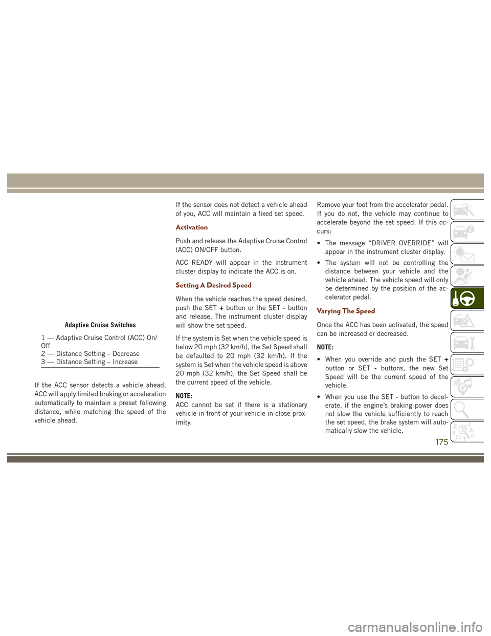
If the ACC sensor detects a vehicle ahead,
ACC will apply limited braking or acceleration
automatically to maintain a preset following
distance, while matching the speed of the
vehicle ahead.If the sensor does not detect a vehicle ahead
of you, ACC will maintain a fixed set speed.
Activation
Push and release the Adaptive Cruise Control
(ACC) ON/OFF button.
ACC READY will appear in the instrument
cluster display to indicate the ACC is on.
Setting A Desired Speed
When the vehicle reaches the speed desired,
push the SET
+button or the SET -button
and release. The instrument cluster display
will show the set speed.
If the system is Set when the vehicle speed is
below 20 mph (32 km/h), the Set Speed shall
be defaulted to 20 mph (32 km/h). If the
system is Set when the vehicle speed is above
20 mph (32 km/h), the Set Speed shall be
the current speed of the vehicle.
NOTE:
ACC cannot be set if there is a stationary
vehicle in front of your vehicle in close prox-
imity. Remove your foot from the accelerator pedal.
If you do not, the vehicle may continue to
accelerate beyond the set speed. If this oc-
curs:
• The message “DRIVER OVERRIDE” will
appear in the instrument cluster display.
• The system will not be controlling the distance between your vehicle and the
vehicle ahead. The vehicle speed will only
be determined by the position of the ac-
celerator pedal.
Varying The Speed
Once the ACC has been activated, the speed
can be increased or decreased.
NOTE:
• When you override and push the SET +
button or SET -buttons, the new Set
Speed will be the current speed of the
vehicle.
• When you use the SET -button to decel-
erate, if the engine’s braking power does
not slow the vehicle sufficiently to reach
the set speed, the brake system will auto-
matically slow the vehicle.Adaptive Cruise Switches
1 — Adaptive Cruise Control (ACC) On/
Off
2 — Distance Setting – Decrease
3 — Distance Setting – Increase
175
Page 189 of 372
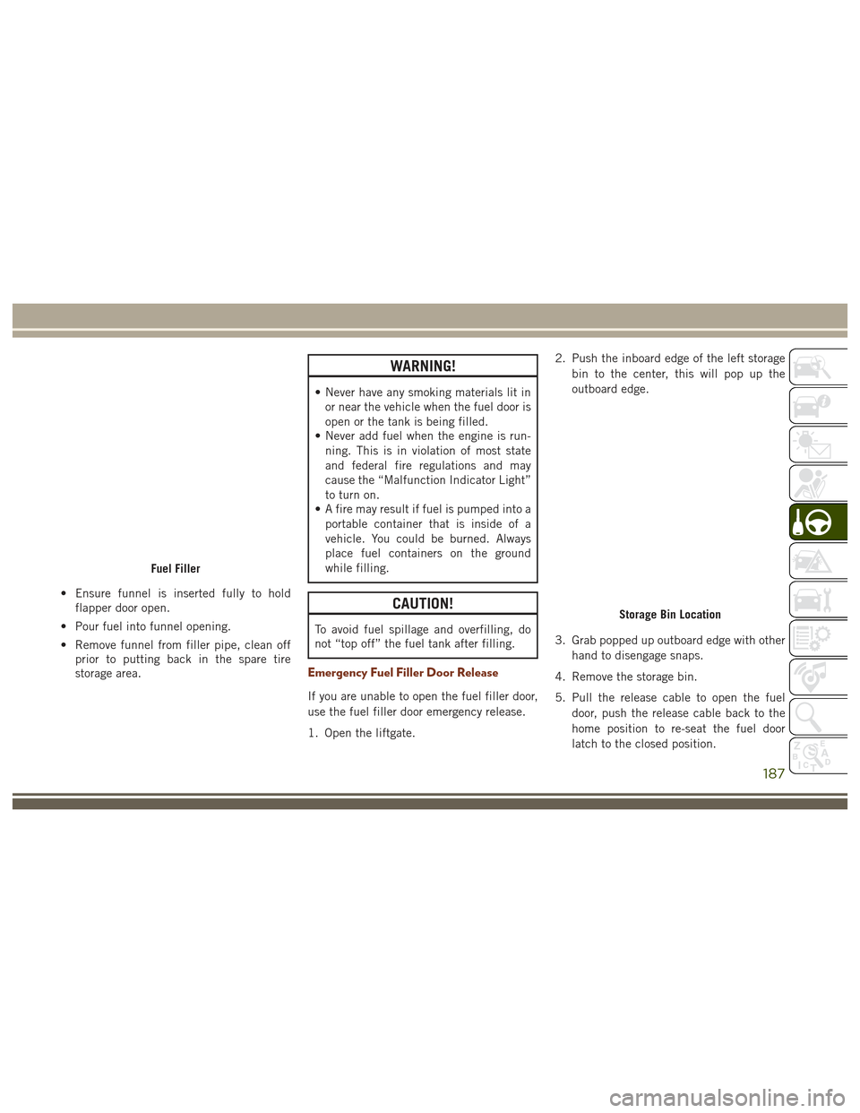
• Ensure funnel is inserted fully to holdflapper door open.
• Pour fuel into funnel opening.
• Remove funnel from filler pipe, clean off prior to putting back in the spare tire
storage area.
WARNING!
• Never have any smoking materials lit in
or near the vehicle when the fuel door is
open or the tank is being filled.
• Never add fuel when the engine is run-
ning. This is in violation of most state
and federal fire regulations and may
cause the “Malfunction Indicator Light”
to turn on.
• A fire may result if fuel is pumped into a
portable container that is inside of a
vehicle. You could be burned. Always
place fuel containers on the ground
while filling.
CAUTION!
To avoid fuel spillage and overfilling, do
not “top off” the fuel tank after filling.
Emergency Fuel Filler Door Release
If you are unable to open the fuel filler door,
use the fuel filler door emergency release.
1. Open the liftgate. 2. Push the inboard edge of the left storage
bin to the center, this will pop up the
outboard edge.
3. Grab popped up outboard edge with other hand to disengage snaps.
4. Remove the storage bin.
5. Pull the release cable to open the fuel door, push the release cable back to the
home position to re-seat the fuel door
latch to the closed position.
Fuel Filler
Storage Bin Location
187
Page 190 of 372
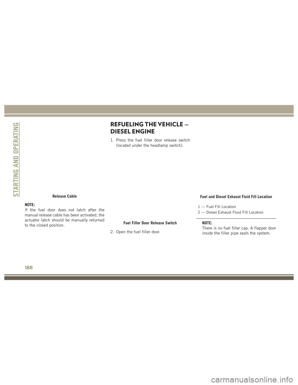
NOTE:
If the fuel door does not latch after the
manual release cable has been activated, the
actuator latch should be manually returned
to the closed position.
REFUELING THE VEHICLE —
DIESEL ENGINE
1. Press the fuel filler door release switch(located under the headlamp switch).
2. Open the fuel filler door.
1 — Fuel Fill Location
2 — Diesel Exhaust Fluid Fill Location
NOTE:
There is no fuel filler cap. A flapper door
inside the filler pipe seals the system.
Release Cable
Fuel Filler Door Release Switch
Fuel and Diesel Exhaust Fluid Fill LocationSTARTING AND OPERATING
188
Page 192 of 372
WARNING!
• Never have any smoking materials lit inor near the vehicle when the fuel door is
open or the tank is being filled.
• Never add fuel when the engine is run-
ning. This is in violation of most state
and federal fire regulations and may
cause the “Malfunction Indicator Light”
to turn on.
• A fire may result if fuel is pumped into a
portable container that is inside of a
vehicle. You could be burned. Always
place fuel containers on the ground
while filling.
CAUTION!
To avoid fuel spillage and overfilling, do
not “top off” the fuel tank after filling.
Avoid Using Contaminated Fuel
Fuel that is contaminated by water or dirt can
cause severe damage to the engine fuel sys-
tem. Proper maintenance of the engine fuel filter and fuel tank is essential. Refer to
“Dealer Service” in “Servicing And Mainte-
nance” for further information.
Bulk Fuel Storage — Diesel Fuel
If you store quantities of fuel, good mainte-
nance of the stored fuel is also essential. Fuel
contaminated with water will promote the
growth of “microbes.” These microbes form
“slime” that will clog the fuel filtration sys-
tem and lines. Drain condensation from the
supply tank and change the line filter on a
regular basis.
NOTE:
When a diesel engine is allowed to run out of
fuel, air is pulled into the fuel system.
If the vehicle will not start, refer to “Dealer
Service / Priming If The Engine Has Run Out
Of Fuel” in “Servicing And Maintenance” for
further information.
WARNING!
Do not open the high pressure fuel system
with the engine running. Engine operation
causes high fuel pressure. High pressure
WARNING!
fuel spray can cause serious injury or
death.
Diesel Exhaust Fluid
Your vehicle is equipped with a Selective
Catalytic Reduction system to meet the very
stringent diesel emissions standards re-
quired by the Environmental Protection
Agency.
The purpose of the SCR system is to reduce
levels of NOx (oxides of nitrogen emitted from
engines) that are harmful to our health and
the environment to a near-zero level. Small
quantities of Diesel Exhaust Fluid (DEF) is
injected into the exhaust upstream of a cata-
lyst where, when vaporized, it converts smog-
forming nitrogen oxides (NOx) into harmless
nitrogen (N2) and water vapor (H2O), two
natural components of the air we breathe.
You can operate with the comfort that your
vehicle is contributing to a cleaner, healthier
world environment for this and generations to
come.
STARTING AND OPERATING
190
Page 193 of 372
System Overview
This vehicle is equipped with a Diesel Ex-
haust Fluid (DEF) injection system and a
Selective Catalytic Reduction (SCR) catalyst
to meet the emission requirements.
The DEF injection system consists of the
following components:
• DEF tank
• DEF pump
• DEF injector
• Electronically-heated DEF lines
• NOx sensors
• Temperature sensors
• SCR catalyst
The DEF injection system and SCR catalyst
enable the achievement of diesel emissions
requirements; while maintaining outstanding
fuel economy, drivability, torque and power
ratings.
Refer to “Instrument Cluster Display” in
“Getting To Know Your Instrument Panel” for
system messages and warnings.NOTE:
• Your vehicle is equipped with a DEF injec-
tion system. You may occasionally hear an
audible clicking noise from under the ve-
hicle at a stop. This is normal operation.
• The DEF pump will run for a period of time after engine shutdown to purge the DEF
system. This is normal operation and may
be audible from the rear of the vehicle.
Diesel Exhaust Fluid Storage
Diesel Exhaust Fluid (DEF) is considered a
very stable product with a long shelf life. If
DEF is kept in temperatures between 10° and
90°F (-12° and 32°C), it will last a minimum
of one year.
DEF is subject to freezing at the lowest tem-
peratures. For example, DEF may freeze at
temperatures at or below 12° F (-11° C). The
system has been designed to operate in this
environment. NOTE:
When working with DEF, it is important to
know that:
• Any containers or parts that come into
contact with DEF must be DEF compatible
(plastic or stainless steel). Copper, brass,
aluminum, iron or non-stainless steel
should be avoided as they are subject to
corrosion by DEF.
• If DEF is spilled, it should be wiped up completely.Adding Diesel Exhaust Fluid
The DEF gauge (located on the instrument
cluster display) will display the level of DEF
remaining in the tank. Refer to “Instrument
Cluster Display” in “Getting To Know Your
Instrument Panel” for further information.
NOTE:
Driving conditions (altitude, vehicle speed,
load, etc.) will effect the amount of DEF that
is used in your vehicle.
191
Page 194 of 372
DEF Fill Procedure
NOTE:
Refer to “Fluids And Lubricants” in the
“Technical Specifications” section for the
correct fluid type.
1. Remove cap from DEF fill inlet (located infuel door). 2. Insert DEF fill adapter/nozzle into DEF fill
inlet.
NOTE:
• The DEF gauge may take up to five seconds to update after adding a gallon
or more of Diesel Exhaust Fluid (DEF) to
the DEF tank. If you have a fault related
to the DEF system, the gauge may not
update to the new level. See your autho-
rized dealer for service.
• The DEF gauge may also not immedi- ately update after a refill if the tempera-
ture of the DEF fluid is below 12F
(-11C). The DEF line heater will possi-
bly warm up the DEF fluid and allow the
gauge to update after a period of run
time. Under very cold conditions, it is
possible that the gauge may not reflect
the new fill level for several drives.
CAUTION!
•To avoid DEF spillage, and possible dam-
age to the DEF tank from overfilling, do
not “top off” the DEF tank after filling.
• DO NOT OVERFILL. DEF will freeze be- low 12ºF (-11ºC). The DEF system is
designed to work in temperatures below
the DEF freezing point, however, if the
tank is overfilled and freezes, the system
could be damaged.
• When DEF is spilled, clean the area immediately with water and use an ab-
sorbent material to soak up the spills on
the ground.
• Do not attempt to start your engine if DEF is accidentally added to the diesel
fuel tank as it can result in severe dam-
age to your engine, including but not
limited to failure of the fuel pump and
injectors.
DEF Filler Cap And Fuel Fill
1 — Diesel Fuel Filler
2 — Diesel Exhaust Fluid Filler
STARTING AND OPERATING
192